This is the concluding article on our MakerPlot bi-directional monitoring and control series. Part 5 dealt with using an Arduino Uno to control a setpoint level for a potentiometer value, where MakerPlot displayed the actions of two physical pushbutton switches that are attached to the Arduino in order to change the setpoint level up or down. While we showed you how the Arduino can also output MakerPlot commands as well as analog and digital data to do this, it was still really a one-way communications example as in micro-to-MakerPlot and not the other way around.
This time, we’re going to show you how MakerPlot can go in the other direction to send back information to the Arduino in order to control the firmware’s setpoint value using a Slider control on the Interface screen. All of this capability is embedded in the Arduino’s code using MakerPlot instructions, so it’s a very interesting way to look at how to interact with the micro instead of using a physical front panel with knobs and meters and such. (If you haven’t already done so, you can download a free 30 day trial copy of MakerPlot from www.makerplot.com to follow along.) Let’s get going.
The Basics of MakerPlot Bi-Directional Control
Figure 1 illustrates the intended bi-directional interactions between the Arduino and MakerPlot. In simple terms, we’ll show you how to program the Arduino to ask for Slider information from MakerPlot, and then go on to show you how MakerPlot responds to this request via the same serial link it uses to send analog and digital data.
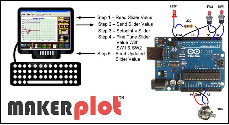
Figure 1. MakerPlot bi-directional data exchange.
Once the Slider value from the MakerPlot Interface screen is acquired, the Arduino sketch can then “fine-tune” this value using the SW1 and SW2 pushbutton switches.
Finally, the fine-tuned Slider value is sent back to MakerPlot where you can see the value change as you push either of the SW1 or SW2 buttons. What this means is that you can start by adjusting the setpoint value with the MakerPlot Slider control with your mouse, then proceed to fine-tune this value with the SW1 and SW2 pushbutton switches. All of this is accomplished in the Arduino sketch using MakerPlot instructions; let’s see how this is done.
Coding for Bi-Directional Data Acquisition and Control
We’re going to continue to use the MakerPlot Interactive Interface (Figure 2) from Part 5 since it’s the one that’s specifically designed for this kind of experimentation and, also, it’s the one Interface in the MakerPlot off-the-shelf suite that has a Slider control.
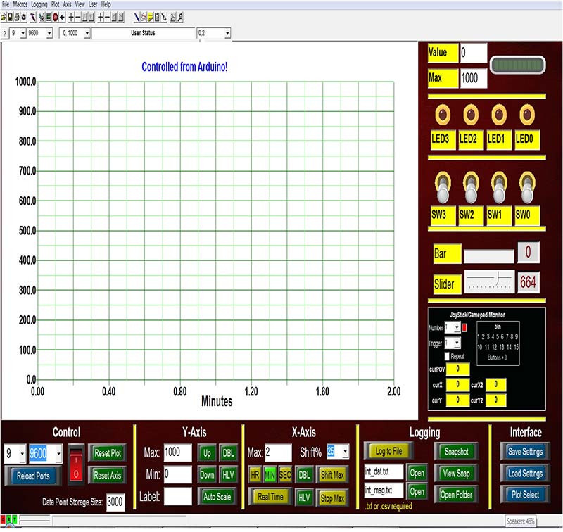
Figure 2. Interactive interface for setpoint example.
Figures 3 and 4 represent the Arduino sketch that does the work just described.
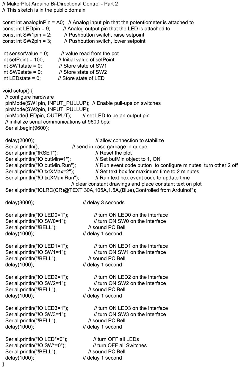
Figure 3. Part 1 of bi-directional setpoint sketch.
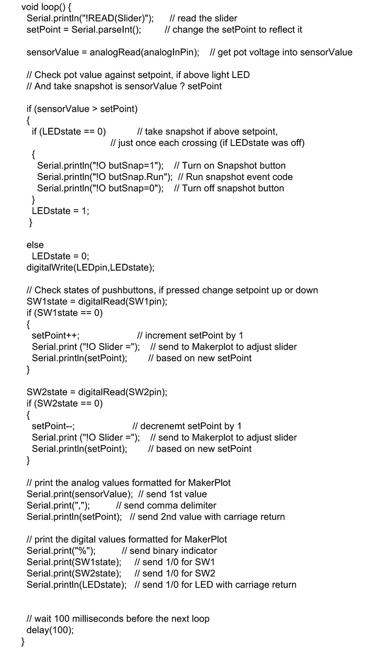
Figure 4. Part 2 of bi-directional setpoint sketch.
As always, you can download and install this sketch by going to www.makerplot.com, then More → Arduino Sketches → Arduino Bi-Directional Control – Part 2. Let’s look at the first part now.
Remotely Controlling MakerPlot
Figure 3 is the Setup part of the sketch, and where the constants and variables are defined. It then goes on to use MakerPlot instructions to configure the Interactive Interface to change the horizontal time axis to two minutes and to display the “Controlled from Arduino” message. We did this in Part 5, so it’s the same.
What’s new is the code that turns the four LEDs and toggle switches ON and then turns them OFF again. We’ve included this in the Setup part of the sketch to run only once in order to illustrate how your micro can send MakerPlot instructions via the serial channel to affect controls on the Interface. Here’s what it does.
There are four LEDs and toggle switches on the top of the Interactive Interface (Figure 2). Normally, these controls would react to your mouse clicks by changing state but, instead, this part of the code does it from the Arduino. It’s important to understand how it’s done, since this is how to control MakerPlot from your micro.
Looking at the first group of instructions below, you can see how the !O prefix alerts MakerPlot to the fact that what follows next is an instruction. These three instructions simply turn on LED0 and SW0, and sound the bell audio tone. Then, it delays for a second. There are three more code groups that do the same thing for the other three LEDs and toggle switches:
Serial.println("!O LED0=1"); // turn ON LED0 on the interface
Serial.println("!O SW0=1"); // turn ON SW0 on the interface
Serial.println("!BELL"); // sound PC Bell
delay(1000); // delay 1 second
While this group of instructions turned the LEDs and toggle switches ON one at a time, the next three lines of code turn OFF all the LEDs and toggle switches all at once:
Serial.println("!O LED*=0"); // turn OFF all LEDs
Serial.println("!O SW*=0"); // turn OFF all Switches
Serial.println("!BELL"); // sound PC Bell
delay(1000); // delay 1 second
If you look closely, this is done with the “Wild Card” asterisk (*) symbol that tells all MakerPlot controls that have “LED” or “SW” as their labels to turn OFF (logic 0). So, although you can’t physically see what happens to the LEDs and toggle switches in this article, you can go to www.makerplot.com → More → Videos → Learn and find the Arduino Bi-Directional Control – Part 2. You’ll also have the benefit of seeing first hand what happens to the rest of the setpoint code that is described next.
Sliding into Home
Now, let’s show you how our new setpoint adjustment using the MakerPlot Slider control and the Arduino’s SW1 and SW2 pushbutton switches work. Figure 4 is the loop part of the sketch that does it; this is how it begins:
void loop() {
Serial.println("!READ(Slider)"); // read the slider
setPoint = Serial.parseInt(); // change the setPoint to reflect it
// get pot voltage into sensorValue
sensorValue = analogRead(analogInPin);
The first instruction sent to MakerPlot is the !READ (Slider). The Slider control on the Interactive Interface goes from 0 to 1000, so this instruction pulls this value into the Arduino’s UART buffer. Following this, the next (Arduino) instruction pulls this value out of the UART buffer and places it in the SetPoint variable using the Arduino Serial.parseInt() instruction. So, this is how we do Steps 1, 2, and 3 in Figure 1.
The last instruction in this section simply reads the potentiometer value (0 to 1023) into the SensorValue variable, which we’ll eventually compare against the SetPoint. So, with these three lines of code, we now have the Slider value from MakerPlot, as well as the potentiometer value in separate variables. We could have stopped there, but we also wanted to get the two pushbutton switches involved in order to fine-tune the SetPoint value. Here’s how that is done.
Fine-Tuning Things
Skipping over the part of the code that snaps an image of the Interface if the setpoint value is exceeded, let’s proceed to the part that adjusts the SetPoint variable:
// Check states of pushbuttons, if pressed change setpoint up or down
SW1state = digitalRead(SW1pin); // get SW1 state
if (SW1state == 0) // test for SW1 depressed
{
setPoint++; // increment setPoint by 1
Serial.print ("!O Slider ="); // send to Makerplot to adjust slider
Serial.println(setPoint); // based on new setPoint
}
SW2state = digitalRead(SW2pin); // get SW2 state
if (SW2state == 0) // test for SW2 depressed
{
setPoint--; // decrenemt setPoint by 1
Serial.print ("!O Slider ="); // send to Makerplot to adjust slider
Serial.println(setPoint); // based on new setPoint
}
The code is pretty straightforward:
• Read the switches (SW1 then SW2).
• See if either are depressed.
• If so, increment (SW1) or decrement (SW2) the SetPoint variable.
• Send the new setpoint to MakerPlot via the !O Slider = SetPoint command.
This part of the code satisfies Steps 4 and 5 in Figure 1. What follows is just sending the pot value along with the pushbutton switch settings to MakerPlot for plotting. Then, there’s the 100 millisecond delay and everything repeats.
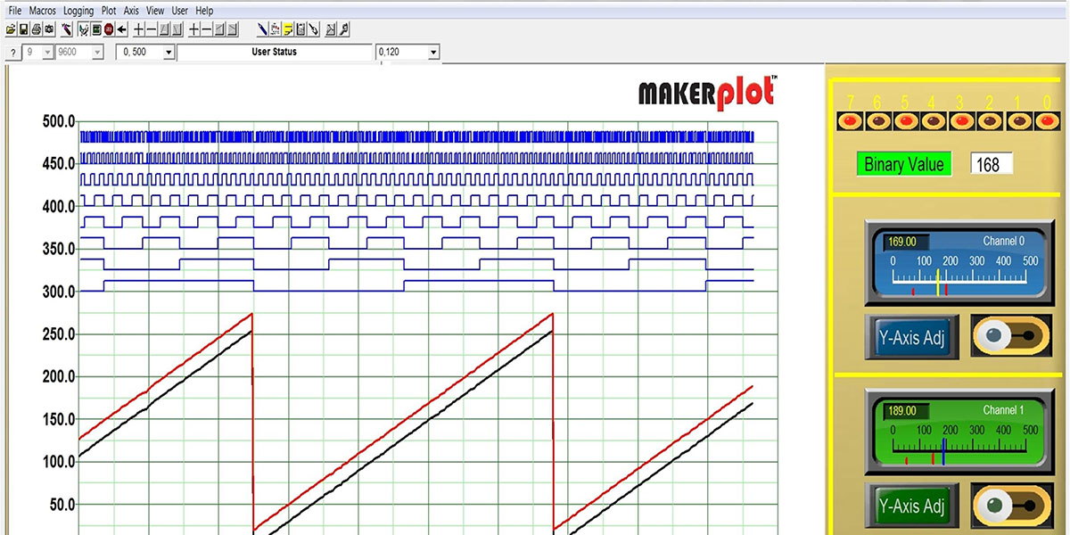
Figure 5 is just one screenshot of what it looks like.
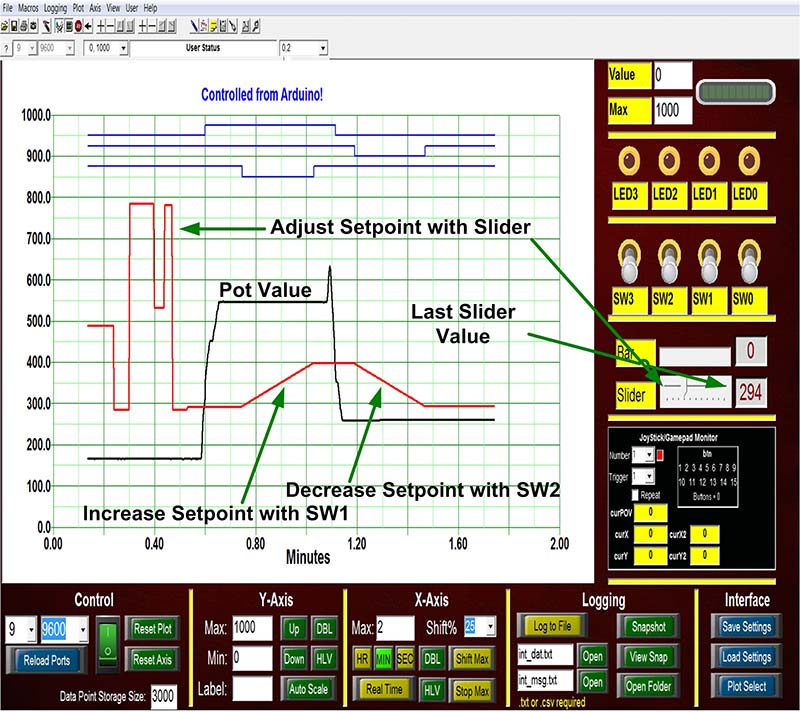
Figure 5. Bi-directional control using slider and pushbutton switches.
Behind the Scenes
Now that you’ve been shown how to code the Arduino to allow MakerPlot to monitor and control the setpoint, there’s another MakerPlot feature we want to introduce you to: the Logs(Debug) Immediate window. The Logs(Debug) Immediate window can display a complete record of all data and other activities in MakerPlot. It is the primary MakerPlot debug tool!
You can bring up the Logs(Debug) Immediate window by clicking on the Logbook icon on the toolbar. It’s shown in Figure 6 where it’s displaying the last part of the setpoint adjustment.
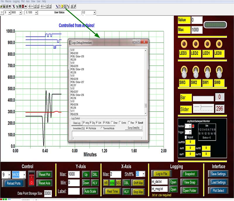
Figure 6. Behind the scenes with the Logs (Debug) Immediate window.
Here, you can see not only the analog and digital data coming in from the Arduino, but also the READ values of the Slider control that MakerPlot sent back. That’s followed by the !POBJ Slider = xxx values that the Arduino sketch sends back to MakerPlot to adjust the Slider control.
Without going into too much detail, the take-away from this is that with the Logs(Debug) Immediate window, you have a complete record of what MakerPlot “sees” as data, and instructions are recorded both coming and going.
The Logs(Debug) Immediate window is invaluable in not only debugging general data but also in learning how MakerPlot works behind the scenes. As a matter of fact, that’s how this series of articles began by showing you how MakerPlot can be a great debugging tool for your micro’s code.
Conclusion
So, to sum up our bi-directional example to this point, we showed you how you can use MakerPlot as a front panel GUI to monitor and control your micro’s code. In effect, anything you see on the MakerPlot Interface is accessible and controllable from your micro — whether it’s an Arduino or whatever. We could go on with much more about bi-directional control, but that will be left to your imagination.
Remember, MakerPlot is all about customization and interactive control, so we’re sure you’ll think up ways to make it interact with your particular application the way you want it to.
For the next article, we’re going to get more into the Logs(Debug) Immediate window capabilities as it will help you immensely in understanding how MakerPlot works. In the meantime, remember that MakerPlot is available as a free trial download. If you like what you see and what it does, you can order it from the NV Webstore at a discounted price.
That’s all for now, so just remember: Got Data – MakerPlot It! NV