Embedded systems, smart devices, and the Internet of Things (IoT) are changing the way we interact with ordinary objects and electronic devices. This article explores a different way of interacting by using a Translational Reality Interface.
Introduction
At the forefront of technological development today are smart devices, IoT, simulation, and virtual and augmented reality. Extensions of these technologies — in the form of a translational reality interface — can be used to create interfaces that translate the interaction of one device to the interaction of another remote device. Such an interface would be of benefit, for example, when the user doesn’t want to bother learning how to interact with a new device, there are security concerns surrounding the direct use of the second device, and when the direct interaction with the second device is dangerous, dull, or dirty.
Basics of Translational Reality Interfaces
First, let’s look at the basic principles of a translational reality interface using a nearby lamp with an adjustable light output level and a remote audio device with adjustable volume, as highlighted in Figure 1.
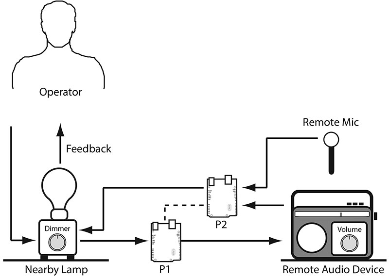
FIGURE 1. A lamp as a translational reality interface to a remote audio device.
In this example, the operator interacts with the lamp by adjusting the dimmer knob and observing the resulting illumination. Let’s say turning the knob clockwise increases illumination and a counter-clockwise turn decreases illumination. Clearly, if the goal were to simply vary the brightness of the bulb, we would simply use a generic dimmer switch and lamp assembly.
However, our goal isn’t to control the light output of the lamp, but to control the volume of the remote audio device. Instead, the desired illumination setting is communicated to the remote audio device as a volume control value. In this way, the operator controls the volume of the audio device by adjusting the dimmer knob on the lamp.
Now, completing the loop back to the lamp, either a microphone picks up the audio from the room or the audio is picked up directly from the remote device. The signal is processed and communicated to the dimmer circuitry, thereby determining lamp brightness.
If the devices in Figure 1 are smart devices with web connectivity, then communications can be handled over the Internet. Alternatively, as in the figure, the processor(s) could be connected by cables to the lamp and audio device.
Let’s Build Something
A translational reality interface can be based on a variety of device combinations with one or more control parameters.
Table 1 lists examples of everyday devices that make good translational reality interface devices.
| TR Interface Device |
User Interaction |
Input(s) |
Output(s) |
| Toaster |
Toast Darkness Preference |
Darkness Setting |
Toasted Bread |
| Light Dimmer |
Light Level Preference |
Light Level Setting |
Lumens |
| Audio Amp |
Volume, Gain, Balance, Treble, Bass Preferences |
Various Settings |
Sound Level Spectral Output |
Table 1. Examples of translational reality interface devices.
Table 2 lists devices that can be indirectly controlled through a translational reality interface.
| Indirectly Controlled Device |
Input(s) |
Output(s) |
Sensor(s) |
| Irrigation Pump |
Water Pump Setting |
Soil Humidity |
Soil Moisture |
| Light Dimmer |
Light Level Setting |
Light |
Light |
| Variable Color Lamp |
Light Color Settings |
Light |
Light, Color |
| Audio Amp |
Volume, Gain, Balance, Treble, Bass |
Audio |
Microphone(s) |
| Robotic Arm (servo) |
Position Directive |
Joint Angle, Distance, Speed |
US Distance, IR Distance, Accelerometer |
| Timer |
On/Off Time(s |
Power On/Off |
Voltage, Current |
| Humidifier |
High/Low Setting |
Rate |
Humidity Sensor |
Table 2. Examples of possible indirectly controlled devices.
A Translational Reality Toaster
To illustrate a translational reality interface in action, I chose a toaster because it’s one of the simplest, cheapest, and most used household appliances. You can’t get much simpler than a toaster. You set the preferred darkness of the toast, pop in a couple slices of bread, push down on the cage lever on the toaster, and wait. After a couple minutes, the toast pops up.
This translational reality toaster is a bit different. I’m using it as an interface to an irrigation pump system (see Figure 2).
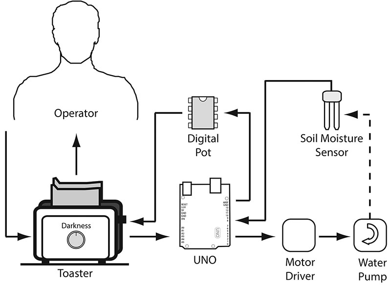
FIGURE 2. Translational reality toaster interface system overview.
If the toast is overdone, it’s an indication that the soil is dry. Adjusting the doneness setting increases the rate at which the watering pump irrigates the soil. That is, when you operate the toaster, you’re not only turning bread into toast, you’re monitoring and controlling soil moisture by adjusting the rate at which the water pump operates.
A soil moisture probe senses the resistivity of the soil, and this signal is sent to the signal processor to provide the basis for the actual toaster darkness setting.
At this point, you’re probably asking why anyone would go through all this trouble to water a plant. After all, a microprocessor controlled pump would do the job.
The goal here is to provide you with a simple experiment that will allow you to explore the possibilities with a translational reality interface that can override the automated irrigation system. Once you’re comfortable with this overly simplified example, you can try it on your grandmother’s pill dispenser, home burglar alarm, and other more practical applications.
Key components include an Arduino Uno microprocessor, a 4131 digital potentiometer, a soil moisture sensor, a toaster, and a water pump with controller (see Figure 3).
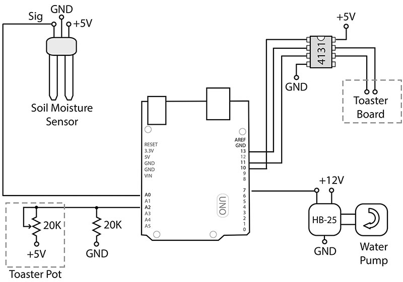
FIGURE 3. Schematic for the toaster-pump control system.
The digital potentiometer — a Microchip MCP4131-503 E/P (approx $0.70, Mouser) — is the digital equivalent of a 50K linear potentiometer. It replaces the 20K darkness potentiometer in the toaster. The digital pot has 128 steps, meaning the 50K digital potentiometer step size is 50K/128 or about 390 ohms. That translates to 20K/390, or about 50 steps to replace a 20K pot.
The soil moisture sensor (approx $5-$7, SparkFun) requires 5 VDC, ground, and an analog port on the Arduino to measure soil conductivity. The toaster (a Hamilton Beach Two Slice Cool Touch) is easy to crack open and modify. The irrigation system is built around a 12 VDC HomeCube peristaltic liquid pump (check Amazon) and a few feet of aquarium air pump tubing. The motor controller is a Parallax HB 25, which is admittedly overkill for such a small motor.
At full speed, the pump/controller combination draws only 350 mA at 12 VDC. Just about any motor controller and pump configuration designed around the Arduino will work. I just happened to have this pump/controller combination available from another project.
The 20K toaster pot is read by creating a voltage divider with a fixed 20K resistor in series with the toaster potentiometer. When the toaster pot is dialed to zero resistance, the full 5V appears across the fixed 20K pot, which is connected to analog port A2. At full resistance — 20K — the voltage drop across the fixed resistor is half of the 5V supply, or 2.5V.
The most challenging part of this project is modifying the toaster controller board. As in most of the toasters I’ve torn down, the darkness setting potentiometer in this unit controls the release of an electromagnet attached to the spring-loaded toast carriers. The specifics of the circuit in your toaster don’t really matter, as long as you can substitute a digital potentiometer for the darkness setting potentiometer.
On my Cool Touch toaster, the 20K darkness setting potentiometer is mounted in the center of the controller board as shown in Photo 1.
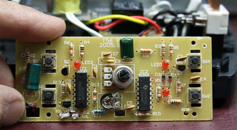
PHOTO 1. Component side of toaster controller board. The 20K darkness setting potentiometer is in the center of the board.
The traces connecting the potentiometer to the control circuit are shown in Photo 2. The probe is on the wiper arm of the potentiometer.
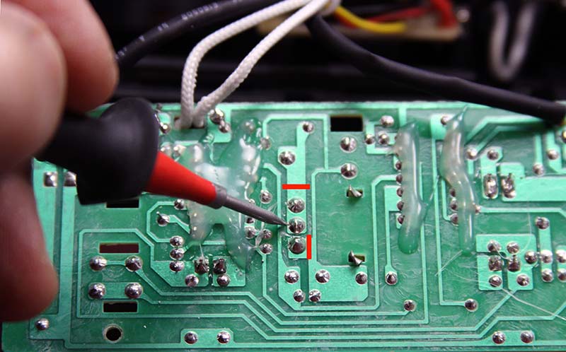
PHOTO 2. Trace side of controller board. Probe is on the wiper arm of the darkness setting potentiometer. Red lines indicate where to cut the trace.
Cut the traces on the potentiometer to isolate it from the rest of the circuit board. If you’re using a Cool Touch toaster, make the cuts as shown in Photo 2. Next, connect two wires of a cable to the circuit trace to replace the onboard potentiometer. These go to the analog output of the digital potentiometer.
Solder two wires of a cable to the pads connected directly to the potentiometer.
These go to an analog input port and a ground connection on the Arduino. I used a single four-conductor cable, but you can also use a pair of two-conductor cables to make the connections.
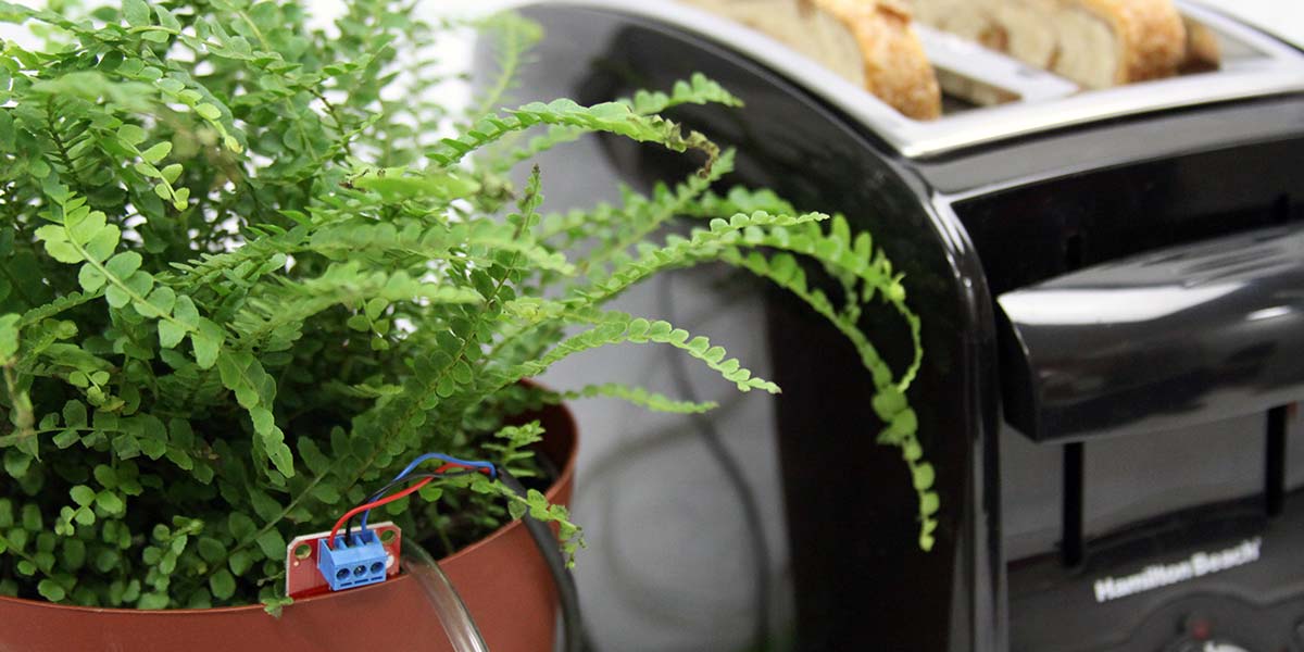
The soil moisture sensor and pump system are shown in Photo 3.
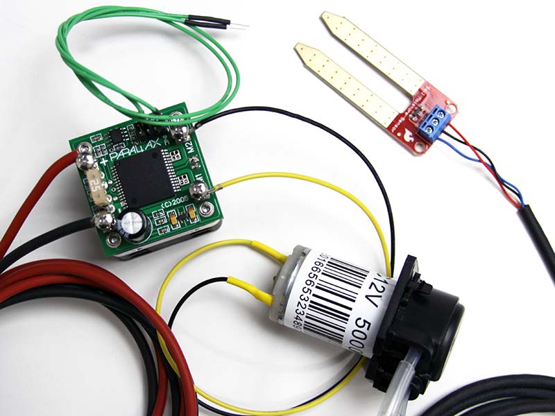
PHOTO 3. Soil moisture sensor and controller-pump assembly. Feel free to substitute a pump/motor controller of your choice.
Consider weatherproofing the connections to the soil moisture sensor, and adding a splash proof housing for the motor and other electronics if you plan to mount the electronics outside.
I used a prototyping shield with screw terminals on the Arduino Uno to facilitate testing and hookup as shown in Photo 4.
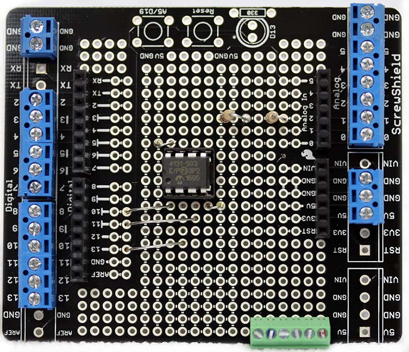
PHOTO 4. Digital potentiometer mounted on screw terminal shield for the Arduino. The eight-pin digital potentiometer is mounted in the center of the shield.
I also used a socket for the digital potentiometer so that I can swap in a 10K or 100K version for other projects. You can see that I used two 10K resistors instead of a single 20K resistor for the soil moisture sensor voltage splitter circuit.
There are two major safety issues associated with working with a toaster. The first is heat.
Make certain the wires are physically bonded to the board before you solder, and verify that the wire insulation can take the high temperatures.
The other issue is working with 110 VAC. Although the board on my toaster is powered by 12 VDC, assume the leads carry 110 VAC until proven otherwise.
The Software
A partial listing of the source code for the project is shown in Listings 1-3. As you can see in Listing 1, standard Arduino libraries do most of the heavy lifting.
#include <SPI.h>
#include <Servo.h>
#define STOP 1500
#define SLOW 1800
#define MED 1850
#define FAST 1900
#define FASTER 1950
#define FASTEST 2000
#define controlPin 7
#define ToasterPin 2
#define DRY = 15;
byte address = 0x00;
int CS = 10;
int sensorPin = A0;
int PotValue = 0;
const int sensorMin = 0;
const int sensorMax = 1024;
const int ToasterMin = 512;
const int ToasterMax = 1000;
Servo servo;
void setup()
{
pinMode (CS, OUTPUT);
SPI.begin();
delay(5);
pinMode(controlPin, OUTPUT);
digitalWrite(controlPin, LOW);
servo.attach(controlPin, 800, 2200);
servo.writeMicroseconds(STOP);
}
void loop()
{
int TempValue = analogRead(sensorPin);
int range = map(TempValue, sensorMin, sensorMax, 0, 52);
PotValue = range;
digitalPotWrite(PotValue);
int ToasterPot = analogRead(ToasterPin);
int pumpSpeed = map(ToasterPot, ToasterMin, ToasterMax, 4, 0);
switch (pumpSpeed) {
case 0:
servo.writeMicroseconds(FASTEST);
break;
case 1:
servo.writeMicroseconds(FASTER);
break;
case 2:
servo.writeMicroseconds(FAST);
break;
case 3:
servo.writeMicroseconds(MED);
break;
case 4:
servo.writeMicroseconds(SLOW);
break;
}
delay (1000);
}
int digitalPotWrite(int value)
{
digitalWrite(CS, LOW);
SPI.transfer(address);
SPI.transfer(value);
digitalWrite(CS, HIGH);
}
Listing 1. Arduino source code.
For example, the digital potentiometer (an SPI device) relies on the SPI library. After the constants and variables and output pins on the Arduino are identified, the Setup routine initializes the SPI and motor controller. The main loop consists of repeatedly reading the soil sensor value and setting the value of the digital potentiometer accordingly, followed by reading the toaster potentiometer and setting the pump speed. The actual writing to the digital potentiometer is called out as the program’s only subroutine.
Comments are omitted here for clarity. The actual source code file in the downloads is commented and contains numerous print line statements for ease of debugging. I’ve included a few additional mapping functions that you can try with the toaster-to-pump control section, shown in Listings 2 and 3.
if (range < DRY) {
PotValue = 0;
}
Listing 2. Alternative mapping, comparing sensor reading to a definite ‘dry’ condition.
switch (range) {
case 0:
PotValue = 54;
break;
case 1:
PotValue = 41;
break;
case 2:
PotValue = 27;
break;
case 3:
PotValue = 13;
break;
case 4:
PotValue = 0;
break;
}
Listing 3. Alternative mapping to one of five digital potentiometer settings, corresponding to 0-20K.
You may need to tweak the code to reflect the particulars of your components, composition of the soil, area receiving water, and proximity of the pump output to the soil moisture sensor.
Taking It from Here
Consider the toaster code a basic framework upon which you can build. For example, you could add a momentary switch to indicate your preferred toast darkness. If your budget allows, consider going Wi-Fi or BT wireless. Try a more powerful microcontroller. Add sensor channels, and explore the use of multiple sensors of different types. In addition to linear and log potentiometers, try magnetic reed switches, Hall effect sensors, proximity sensors, motion detectors, and accelerometers.
If you’re a robotics experimenter, then you might look into speed and distance sensors. I’ve had great luck with the PING))) ultrasonic distance sensor. For shorter ranges, the Sharp GP2Y0A21YK0F IR is a good choice — especially for a robotic arm sensor where sensor weight and size are critical. Both sensors are available from Parallax.
Once you get a handle on the translational reality approach, it’s easy to see that you’re primarily limited by your imagination. Who knows, one day some of us will be able to log into our favorite video games and be paid for a full day’s “work” for unknowingly operating a surveillance drone or directing a robot to perform emergency surgery on a soldier in the battlefield. Ponder that over your next breakfast of toast and jam. NV
Translational Reality Defined
Translational reality is a real time closed-loop system in which a user operates a familiar first device and, in so doing, both monitors and controls a second device. User feedback is appropriate to the first device, but reflects the operation of the second device.
Digital Potentiometers
Digital potentiometers are mixed analog-digital devices. The digital side communicates with a digital microcontroller and the analog side is essentially a three-terminal analog potentiometer. When selecting a digital potentiometer, consider the voltage rating, current rating, resistance range, and the step size. For example, a 5V device won’t do if you’re splitting a 12 VDC signal. The current rating for digital potentiometers is typically well below 50 mA, so think of digital potentiometers as relatively delicate low power devices. Choose a resistance range and step size to match circuit requirements.
Why Not Simply Fully Automate?
With the simple example provided in this tutorial, an obvious question is why not simply fully automate the second system. After all, even complex automobiles are going fully autonomous. The point of a translational reality interface is to provide for human monitoring and control when full automation isn’t practical or possible.
Downloads
What’s in the zip?
Source code