Radio and wireless are all about waves and how they link distant points together, so we'll be learning about RF propagation in this mini series.
One key element of ham radio is propagation — the way radio signals get from Point A to Point B. Lots of projects in Nuts & Volts involve wireless links, so it behooves the builder to have a bit of an idea about how propagation works. After all, with so many choices available, you need information to understand your requirements for choosing the right technology and installing it properly. We’ll start with some basics of radio waves, then get them bouncing around.
Electromagnetic Waves
It would be easy to write a whole magazine’s worth of material about electromagnetic (EM) waves and leave the reader more uncertain on the subject than before starting. Let’s finesse things a bit by saying that EM energy moves through space as a wave composed of an electric (E) and a magnetic (H) field that oscillate like sine waves at right angles to each other. The energy in the wave is carried by both fields. Figure 1 shows the E and H fields of an EM wave moving together through space.
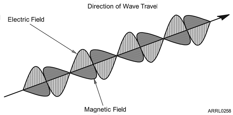
FIGURE 1. The E (electric) and H (magnetic) fields of a vertically polarized electromagnetic (EM) wave moving to the right. The fields vary in the pattern of a sine wave and are oriented at 90 degrees to each other. (Graphic courtesy of the ARRL.)
Note that the fields are not only at right angles to each other, they are at right angles to the wave’s motion through space.
The E and H fields don’t just happen to be in the same place at the same time. They are coupled because they are created by the same thing: an electric charge (usually an electron) that has been terribly inconvenienced from being accelerated by a voltage at the frequency of the wave. Without this acceleration of charge — current in an antenna, for example — no EM wave is produced. (An animation of the field produced by a moving charge is available at en.wikipedia.org/wiki/Radio_wave.)
The EM wave would be useless for signaling unless we could reverse the process and have the wave cause an electron to accelerate, thus creating a current. That is just what happens when a radio wave is received by an antenna. The E field of the wave creates a voltage in the antenna and that causes the electron to move. If the E field is oscillating back and forth in a sinusoidal pattern, then the electron will do the same. Antennas are bilateral, meaning that they work the same in both “directions.” In fact, the whole process is so reversible that according to the math, it can even run backwards in time!
At the transmitting antenna — the one in which voltage accelerates electrons and causes them to radiate EM energy — the E field of the wave radiated by the antenna is aligned with the direction in which the electron is accelerated. Similarly on the receiving end, the antenna needs to be aligned with the E field of the EM wave for the E field to cause the electrons to move in the antenna and produce a detectable current. The alignment of the wave’s E field is thus very important, and so its direction is defined as the wave’s polarization.
If the wave is vertically polarized, then the E field is aligned perpendicularly to the Earth’s surface. The E field of a horizontally polarized wave is parallel to the Earth’s surface. The polarization of an antenna is determined by the polarization of the EM waves it radiates, so there are horizontally polarized and vertically polarized antennas, too. There are even circularly polarized waves (and antennas) in which the direction of the E and H fields gradually rotates as the wave moves along. Circular polarization has a right-handed and left-handed sense as well, depending on which way the fields rotate.
What’s important to remember about polarization is that the receiving antenna and the EM wave must have the same polarization for the wave to create the maximum amount of current in the antenna. If the antenna and wave’s E field are at right angles, then instead of the E field causing the electrons to accelerate back and forth along the antenna, the electrons move back and forth across the conductor of the antenna instead of along the antenna. The difference in received signal strength when an antenna is cross-polarized to the EM wave can be a factor of 100 (20 dB).
Frequency and Wavelength
There is another important part of understanding waves in general and that is the three-way relationship between frequency, velocity, and wavelength. One of those three — frequency, f — stays the same as the wave travels along. Velocity also stays the same as long as the medium in which the wave travels stays the same. That velocity, c, is the speed of light (also an EM wave) in whatever medium the wave finds itself moving through — from the plastic of a coaxial cable to the vacuum of free space. The properties of the medium (primarily its permittivity, ε, and permeability, μ) determine the velocity, with free space having the highest value for c = 3 x 10⁸ m/sec. (The velocity in air is only slightly less.)
So, what about wavelength? One wavelength, λ, is the distance traveled by the wave during which the E and H fields undergo one complete cycle of oscillation. Assuming velocity is constant, the faster the wave’s fields oscillate, the shorter the wavelength becomes because it takes less time to complete the cycle and vice versa. There is a great animation of acoustic waves that demonstrates this relationship at resource.isvr.soton.ac.uk/spcg/tutorial/tutorial/Tutorial_files/Web-basics-frequency.htm.
The relationship of f, c, and λ is captured in this simple but powerful set of equations:
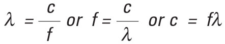
For l to have units of meters, f must be in Hertz (Hz), and c in meters/second.
The relationship can be greatly simplified for calculating the free-space wavelength of an EM wave as:
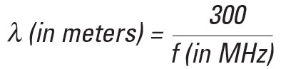
If c is lower because of what the wave is moving through, then the wavelength gets shorter, too. When we are talking about the wave moving along a printed circuit board (PCB) trace or a transmission line, this shorter wavelength is called the electrical wavelength. To give you an idea of how much shorter, the velocity of EM waves in coaxial cable with a solid polyethylene dielectric is about two-thirds of the free-space velocity, and the wavelength in coaxial cable is only two-thirds of the free-space wavelength. You have to take this shorter wavelength into account when designing antenna systems, especially.
Omnidirectional and Directional Antennas
Speaking of antennas, we need to launch our waves from an antenna and receive them with an antenna. There are several common types of antennas our wireless systems commonly use, but they are of two basic classes: omnidirectional and directional. The first type’s job is to radiate and receive signals (modulated waves carrying information) in all directions as equally as possible. You met one type of “omni” in this column’s first installation which showed how to build a simple quarter-wavelength long whip. That antenna radiated (and received) best in all horizontal directions when held vertically, and so is used on handheld radios, wireless routers, vehicle radios, and so forth. Other types of omnis — such as Lindenblads, turnstiles, and the quadrifilar helix in Figure 2 — cover a whole hemisphere of the sky and are used for satellite communications.
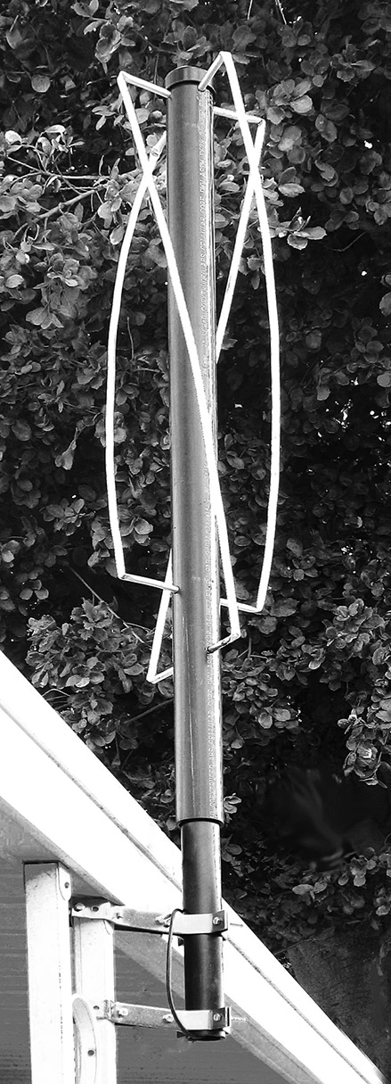
FIGURE 2. This quadriflar helix built by W6NBC is used for receiving image signals from the NOAA weather satellites at 137 MHz. As an omni-directional antenna, it receives equally well over most the sky. (Photo courtesy of the ARRL.)
While an omni antenna is convenient to use because it is relatively unaffected by its orientation, it spreads its signal all over which means less signal at the one point it is really needed: the receive antenna. When a more reliable link with stronger signals are needed and more transmitter power is not available (or allowed), directional antennas are used. Directional antennas work by focusing the available EM energy in the desired direction. They don’t create energy, just focus it; this is a property called gain.
Inside our wireless adapter cards and data link modules you might find a patch antenna — a type of directional antenna. The patch looks just like its name (see Figure 3), and is shaped so that when it is excited by a signal, the electrons flow along specific paths just as if the antenna was made of wires. The net effect is to create a directional antenna that is simple and inexpensive to fabricate for consumer and low cost electronics.
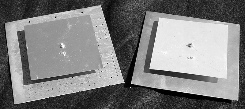
FIGURE 3. These two homemade patch antennas are designed for use at a wavelength of 23 cm (approx. 1.3 GHz). The antennas are one-half wavelength on a side and are excited at their centers. The patch at left is made from sheet metal and on the right from PCB material. (Photo courtesy of the ARRL.)
You’ve probably seen a beam antenna with lots of parallel rods or wires (called elements) along a central support (called a boom). The transmitter feed line is connected to the driven element near one end, and the other elements (reflectors and directors) guide the waves in the preferred direction. The focusing effect can easily increase signal strength at a receiver by 10 times (10 dB) or more. Arrays of beams can be used for even more gain.
The king of the directional antennas, though, is a dish several wavelengths across as shown in Figure 4.
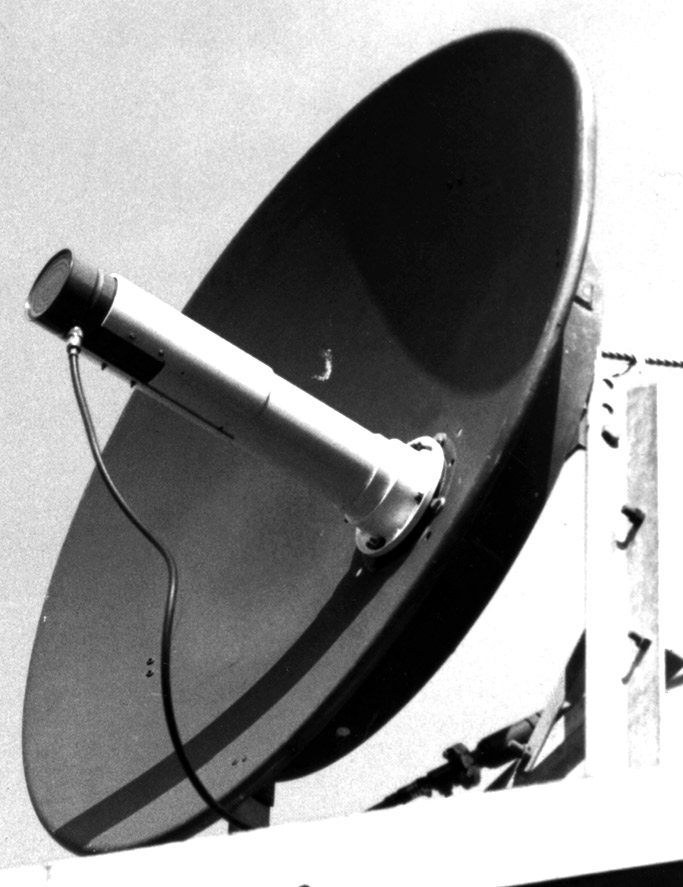
FIGURE 4. This four foot diameter dish antenna is designed for microwave communication in the amateur 2.3 GHz band, but would also work at Wi-Fi's 2.4 GHz. The antenna illuminating the dish's surface is made out of a coffee can! (Photo courtesy of the ARRL.)
It uses a curved reflector (the dish) to focus the radio waves from a feed antenna into a tight beam. Dishes can have gains of 30 dB or more depending on how many wavelengths across they are. That is a gain of more than 1,000!
Multipath
If all there was to propagation was picking the right antennas and pointing them at each other, I would simply suggest you buy a copy of the ARRL Antenna Book and this column would be done! Obviously, the job can get pretty complicated. At the frequencies we’re talking about for unlicensed wireless data links (902 MHz, 2.4 GHz, and 5.6 GHz being the most common), the wavelengths of 33 cm, 13 cm, and 5.4 cm are short enough to be reflected or refracted (bent) by everything from the ground and buildings to desks, windows, and furniture. When a sharp corner or edge is encountered, the signal can be diffracted into a pattern of strong and weak regions. This creates a situation in which the different waves are constructively and destructively interfering with each other.
As an example, when receiving a broadcast FM signal in your car, you’ve no doubt experienced reception that varies as your vehicle moves along. This occurs because signals from the transmitter are taking different paths to you, arriving in and out of phase with each other. This creates a pattern with alternating areas where the waves add together creating a strong signal, and where they cancel each other creating a “dead spot” or null. As you drive through this pattern, you hear the alternating strong and weak spots as “mobile flutter” or “picket fencing.” The peaks and nulls in the signal are about one-half wavelength apart, which for the commercial FM band is about 1-1/2 meters. The next time you pull up at a stop light and your FM station takes a dive into the noise, change the car’s position by about four or five feet and I’ll bet the signal comes right back!
The same thing happens to your data signal when it encounters a field of obstacles and reflecting surfaces. At the wavelengths for unlicensed data signals, the hot spots or dead spots can be just inches apart. This is called multipath propagation and it can cause a data link to be quite unreliable. Wi-Fi routers often try to defeat multipath by using two or more antennas, one-half wavelength apart. This creates two patterns of strong and weak signals that are offset by the half wavelength. This tends to place the peaks of one pattern in the nulls of the other pattern, evening out the signal strength and reducing the number of dead spots.
Scatter
Reflections can also be used to your advantage if they create a signal path more reliable than the direct path. Or, perhaps the direct path is blocked. In cases like this, it’s common to use a directional antenna to find a reflected path around the obstacle or in a direction less affected by multipath. The reflecting surface can be a wall, a building, or even a natural formation. For example, when I lived in Seattle, it was not uncommon to contact someone on a VHF or UHF band by bouncing a signal off Mount Rainier tens of miles away! Not unsurprisingly, this is called scatter propagation.
As an interesting experiment, if you have a Wi-Fi beam antenna you can aim in different directions, plug it into a laptop or tablet’s antenna port. Open the wireless adapter’s configuration software and look for the RSS (received signal strength) indicator. This gives you an indication of how strong the signal is that the adapter is receiving. (Some mobile phones allow you to do this with an external antenna.) Point the antenna in different directions while watching the RSS indicator and note the big variations in signal strength. You will probably find the signal is quite strong in other directions than straight toward your Wi-Fi router or local cell tower.
Scatter propagation does not have to be via a hard surface, either. The scattering surface or structure just needs to be bigger than about one-tenth of a wavelength to reflect a significant fraction of the signal. Hams use all kinds of things to reflect radio signals and increase their range: rain or snow or hail, airplanes flying by, meteor trails that last just a few seconds, and even the moon. If you have ever lost satellite TV service due to heavy rain or snow, the signal from the satellite is being scattered so widely that the amount making it to your antenna is too low to be decoded.
On the Next Transmission
Take a new look at your wireless router. Can you sense the waves boiling off those little antennas? Now you know why they are “that far” apart and also why they are tiltable: so you can change the polarization. The result is to be able to change that pattern of peaks and nulls so you can browse the ‘net from that comfy chair in the living room.
In Part 2 of this mini series, we’ll cover things like the radio horizon, effects of the troposphere (that means “weather”), the shortwave bands, and the ionosphere, plus some really neat tools for assessing and studying propagation. NV
Sidebars
Electromagnetic Waves — Going Deeper
This article barely touches the fundamentals of what an EM wave really is: a form of energy traveling through space as time-varying electric and magnetic fields. If you'd like to dig deeper into the fundamentals of EM waves and can handle a little math, the Wikipedia entry on electromagnetic radiation (en.wikipedia.org/wiki/Electromagnetic_radiation) covers the topic well and provides numerous links to supporting pages and resources. EM waves are a fascinating phenomenon, leading to deep questions and answers about the nature of the universe in which we live.
An Array of Antenna Know-How
The graphics and photos in this article were all taken from the ARRL's Antenna Book, now in its 24th edition (it was first printed in 1939). If you're interested in radio antennas and propagation, this is a great book to have on your shelf, with material spanning from 1.8 MHz to 10 GHz. In addition to the Antenna Book, there are links to numerous ARRL articles and web pages on antennas and transmission lines and propagation at the ARRL's Tech Portal (arrl.org/tech-portal). Be advised — set aside plenty of reading and browsing time because antennas and propagation are one of the deepest and most interesting wireless topics.
Scattering from the Moon and Meteors
You may be quite surprised to learn that actual communication can take place from bouncing radio signals off these celestial reflectors. Such activity is more common today than at any time in amateur radio's history, thanks to software developed by ham radio Nobel Prize winner, Joe Taylor K1JT.
Joe started out in ham radio as a teenager with his brother, experimenting with scatter propagation on the VHF bands. At the Arecibo telescope, he and Russell Hulse developed the necessary expertise to indirectly make the first observation of gravitational waves generated by a binary pulsar. After he returned to amateur radio a decade ago, Joe decided to use that expertise to create software which enabled communication at the extremely low signal levels encountered in "moonbounce" operation and during the short periods of reflection by the ionized trails of meteors.
Joe's software is available as a suite of WSJT protocols (Weak-Signal Joe Taylor), downloadable for free from his Princeton University website at physics.princeton.edu/pulsar/k1jt. All that's needed to get started is an entry-level ham license, a VHF/UHF SSB transceiver, and some surprisingly modest antennas. There are user's groups online to help get started, and you can use the same equipment to operate through ham satellites as well. These are just a few of the fascinating ways for amateurs to interact with the natural world in unexpected ways.