For some time, I have been thinking about building an LED table. Several iterations of table size, array size, type and number of LEDs, mount for the LEDs, circuits to drive the LEDs, and what exactly the array of LEDs would do has been considered. What I finally decided on was to use the popular RGB LED strips that are programmable. These strips are really easy to use and each LED can be programmed with millions of colors. Plus, they don't have to be continually scanned and refreshed. You select an LED and its color — or multiple LEDs — and then simply turn it on. These strips come in different densities (typically 30, 60, and 144 LEDs per meter) and are available from several vendors.
There is one caveat when using these RGB LED strips. When using solid colors like red, green, or blue, the color looks great. However, when you try to create a brown or lime green, for example, you'll find that you have to tinker with the RGB values to get what you want. These strips do not translate the standard RGB triples as accurately as an LCD or LED monitor on a computer.
Adafruit is one supplier of these RGB LED strips, which they call Neopixels. They have some very good tutorials on how to practically use and program them. Go to https://learn.adafruit.com/adafruit-neopixel-uberguide/overview for details. Adafruit’s Neopixel library is excellent and I use it for this project.
Let’s start with a simple example of creating a half meter square array using strips with 30 LEDs per meter. Our array will be 15 LEDs square for a total of 225 LEDs. We'll cut out strips with 15 LEDs and glue the strips down with a spacing of 3.33 centimeters (about 1-5/16 inch) between strips. Looking at the array in Figure 1 and starting at the bottom right corner, the end of each strip needs to be wired to the start of the strip above at its left end.

FIGURE 1. Wiring the strips together.
Looking at this as an X by Y array (X width and Y height), we can use the formula:
num = y * 15 + x
to locate the LED to program. Note that the value 15 is the height of our array. Using the Adafruit Neopixel library, we would use:
strip.setPixelColor(num, red, green, blue); // sets the color, using values 0 - 255 for each color.
strip.Show(); // this turns on the LEDs you have programmed with colors.
Here’s a complete program to draw a blue diagonal from the bottom left corner to the top right corner of our 15 x 15 array:
#include <Adafruit_NeoPixel.h>
#include <avr/power.h>
// When we setup the NeoPixel library, we tell it how many pixels, and which pin to
// use to send signals. In our case 15 x 15 = 225 pixels and we will use pin D6.
// Check the NeoPixel library for using the default NEO_GRB + NEO_KHZ800 value,
// which I found usually works just fine.
Adafruit_NeoPixel pixels = Adafruit_NeoPixel(225, 6, NEO_GRB + NEO_KHZ800);
void setup()
{
pixels.begin(); // This initializes the NeoPixel library.
pixels.setBrightness(32); // This sets the brightness of the LEDs
}
void loop()
{
for(int i=0;i<15; i++)
{
int num = i * 15 + i
// pixels.Color takes RGB values, from 0,0,0 up to 255,255,255
pixels.setPixelColor(num, pixels.Color(0,0,128)); // Moderately bright blue color.
}
pixels.show(); // This sends the updated pixel color to the hardware.
delay(1000); // Delay for 1 second.
}
Here’s another example. Create an array of 16 x 16 LEDs which will represent either a chess or checker board (an 8 x 8 array) using blocks of four LEDs for each square. Here are the four formulas to select the LEDs to turn on for a square at (x,y):
num1 = y * 32 + x
num2 = y * 32 + x + 1
num3 = y * 32 + 32 + x
num4 = y * 32 + 32 + x + 1
My "Current" Project
For my project, I made an array 30 LEDs wide by 10 high. I want two LEDs horizontally to represent each square in my 15 x 10 array. My formula for this 15 x 10 array then becomes num = y * 30 + x * 2. For the second LED, you just add one to num.
Here's what I did. I purchased two five meter long rolls of RGB LED strips. I chose the type that has 30 LEDs per meter with each LED 3.33 centimeters apart. I chose to create a 10 high by 15 wide array on my table top. I should point out that this doesn’t need to be a table; it could also be hung on a wall or mounted in other ways. I’m using two LEDs for each of my 10 x 15 squares, so that’s 2 x 3.33 cm = 6.67 cm or almost exactly 2.625 inches square for each cell.
I cut my LED strips into one meter lengths and used the adhesive strip on the back to mount them on a sheet of 1/4 inch plywood (keeping the rows 6.67 cm or 2.625 inches apart). I built an array of 2.625 inch square boxes using 1/8 inch plywood strips with 1/8 inch wide slits, put together in an interlocking grid.
This grid is placed on top of the LED strips and serves to isolate the colors in each square. A sheet of glass or plastic is placed on the top of the box grid. If this sheet is not clear but diffuses the LED light, it will help even out the color of each box. The technique I used here will work for any size LED array you wish to make, limited only by the number of LEDs you can drive. I'm using 300 LEDs in my project:
- 300 LEDs x 20 mA ÷ 1,000 = 6.0 amps minimum, with all LEDs on with just one red, green, or blue color
- 300 LEDs x 60 mA ÷ 1,000 = 18.0 amps minimum, with all LEDs on which produces white color
Realistically, you're probably not going to hit these high levels of current for any length of time, but they need to be kept in mind. In addition, a very long strip will begin to show a voltage drop at the far end from the power supply and the color of the LEDs will begin to be affected. The current use can also be reduced by using the command pixels.setBrightness(32); in the setup block. The brightness value can be between zero and 255. Because I will not be illuminating all the LEDs at one time, I chose a five volt/three amp wall wart to power my strip.
An Arduino Nano was used to drive the LED RGB array. Along with the minimum amperage issue, driving the single data in line from the Nano to the strip is also a concern. I found that after about a foot of length, this line can give problems. An Internet search uncovered the mention of using line drivers between the Arduino and the strip with success.
I found that using a 7400 series Schmidt trigger also worked. I had a 7413 dual four input NAND Schmidt trigger IC in my parts bin and used this. The two NANDs were wired in series to produce a non-inverting output.
Two additional circuits were added to my design. The first was a mini board with a DS3231 real time clock and the second was a pair of MSGEQ7 seven band graphic equalizer ICs. This is the right amount of LEDs to display a four-digit clock. The pair of MSGEQ7 circuits was used to create a two-channel graphic equalizer display for stereo output on the table.
I have built a number of different digital clocks and have always used the DS3231. The ±2 PPM accuracy of this circuit means your clock will only be off about a minute per year. Recently, some small mini boards have appeared on the market with the DS3231 real time clock and the necessary CR2032 coin battery in a holder for backup. While the DS3234 has an SPI interface, the DS3231 has an I2C interface, making it a little easier to use with fewer connections.
The RTClib library makes using this mini board very easy. RTClib can be found at GitHub at https://github.com/adafruit/RTClib.
The MSGEQ7 circuits are a little more involved, but with the addition of four capacitors and a resistor, you have a single-channel graphic equalizer display; with two, you get a display for stereo output.
Using this circuit is fairly straightforward. After sending a reset pulse, the strobe line is pulsed low and the output is then read using an analogRead() command. This is repeated seven times, giving numeric values from 0-1023 for frequency channels with peaks at 63 Hz, 160 Hz, 400 Hz, 1 kHz, 2.5 kHz, 6.25 kHz, and 16 kHz. The complete schematic for my design is shown in Figure 2.
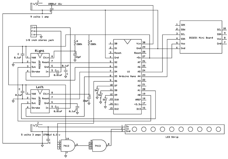
FIGURE 2. Schematic of the Arduino Nano driver board.
The Build
I mounted my RGB LED strips on a 1/4 inch piece of good quality plywood. Reinforcement pieces of 3/4 x 1 inch wood were glued around the edges of the plywood in addition to two added ribs to give the plywood rigidity. Small notches were cut in the edges of the plywood to give the connecting wires a path to the underside of the plywood. A number of holes must also be drilled in the ribs to allow the connecting wires to pass through.
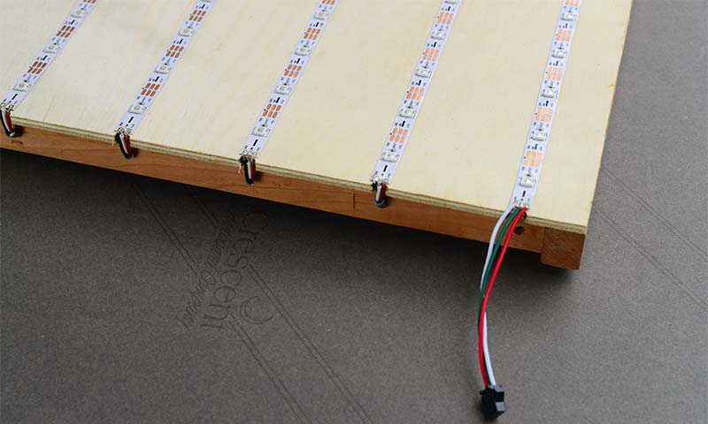
FIGURE 3. Edge of the plywood board the RGB LED strips are mounted on, showing the wiring.
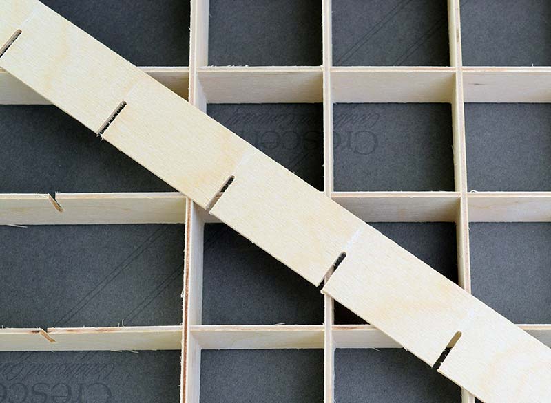
FIGURE 4. Box array, with each box fitting over two LEDs to isolate the colors.
The driver circuit was built on a breadboard with point-to-point wiring. This board was enclosed in a 158 x 90 x 60 mm plastic project box. The sides of the box were pierced with holes for mounting two 5.5 mm jacks for nine volt/one amp and five volt/three amp power supplies (the wall wart type).
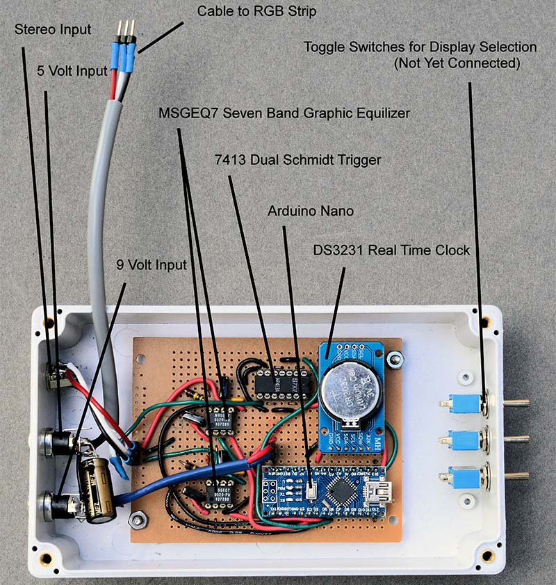
FIGURE 5. Inside the project box, showing component placement.
The five volt power supply is only used to power the RGB LED strip. There is also a 1/8 inch mini jack for a stereo input plug and three small toggle switches to determine which function the driver board will perform. A short three-wire cable was brought out to connect to the RGB LED strip.
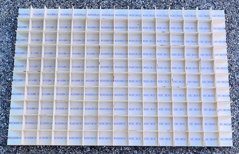
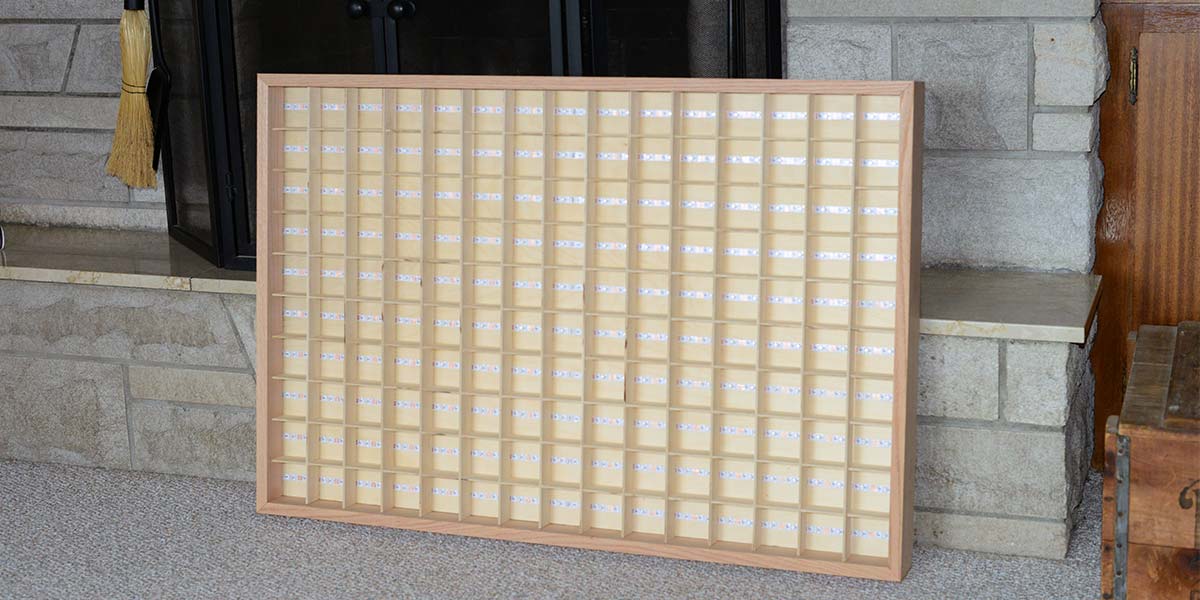
FIGURE 6. The square boxes mounted on top of the RGB LED board.
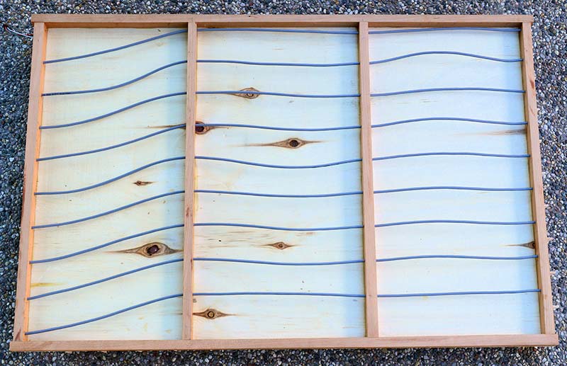
FIGURE 7. Back side of the RGB LED board, showing the wiring between the strips.
Software
The RGB LED table was designed primarily to do two things: display a stereo graphic equalizer and a four-digit clock. Here is the freq() function to display the graphic equalizer:
// Read the two stereo MSGEQ7 audio channels
// and display a graphic equalizer
void freq()
{
int num;
// Read frequencies and display
// Left channel
// Do a reset
digitalWrite(resetPinLeft, HIGH);
digitalWrite(resetPinLeft, LOW);
// Read the left seven frequency channels
for (int i = 0; i < 7; i++)
{
// Set stobe low then read a value
digitalWrite(strobePinLeft, LOW);
// Allow output to settle
delayMicroseconds(30);
// Diving by 103 reduces the 0 - 1023 output to 0 to 9
spectrumValueLeft[i] = analogRead(analogPinLeft) / 103;
// Return strobe to high, ready for another read
digitalWrite(strobePinLeft, HIGH);
}
// Right channel
digitalWrite(resetPinRight, HIGH);
digitalWrite(resetPinRight, LOW);
// Read the right seven frequency channels
for (int i = 0; i < 7; i++)
{
digitalWrite(strobePinRight, LOW);
delayMicroseconds(30);
spectrumValueRight[i] = analogRead(analogPinRight) / 103;
digitalWrite(strobePinRight, HIGH);
// Serial.print(spectrumValueRight[i]);
}
// Now display the results
// Left channel
for (int x = 0; x < 7; x++) // seven channels
{
for (int y = 0; y < 10; y++) // 10 different heights
{ // representing frequency strength
num = y * 30 + x * 2;
if (spectrumValueLeft[x] >= y) // add a color to the bar height
{
pixels.setPixelColor(num, colors[x + 1]);
pixels.setPixelColor(num + 1, colors[x + 1]);
}
else
{ // or fill in the top with no color
pixels.setPixelColor(num, 0, 0, 0);
pixels.setPixelColor(num + 1, 0, 0, 0);
}
}
}
// Right channel
for (int x = 0; x < 7; x++)
{
for (int y = 0; y < 10; y++)
{
num = y * 30 + x * 2 + 16;
if (spectrumValueRight[x] >= y)
{
pixels.setPixelColor(num, colors[x + 1]);
pixels.setPixelColor(num + 1, colors[x + 1]);
}
else
{
pixels.setPixelColor(num, 0, 0, 0);
pixels.setPixelColor(num + 1, 0, 0, 0);
}
}
}
// After every LED is programmed turn them on
pixels.show();
}
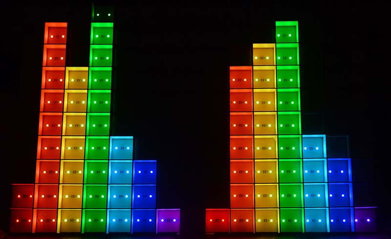
FIGURE 8. RGB LED table functioning as a stereo graphic equalizer.
These two functions read the DS3231 real time clock and display the results:
// Read and display the time
// hourmin set to HOUR for a 4 digit hour and minute clock
// or MIN fpr a 4 digit minute and second clock
void getTime(int hourmin)
{
// Read the current time from DS3231 RTC
DateTime now = rtc.now();
int h = now.hour();
if (h > 12) h = h - 12; // a 12 hour clock, remove for 24 hour
int m = now.minute();
int s = now.second();
// now split into 10s and 1s digits
int h10 = h / 10;
int h1 = h % 10;
int m10 = m / 10;
int m1 = m % 10;
int s10 = s / 10;
int s1 = s % 10;
// Now display the 4 digits
switch (hourmin)
{
case HOUR: setLedNumbers(h10, 0);
setLedNumbers(h1, 1);
setLedNumbers(m10, 2);
setLedNumbers(m1, 3);
break;
case MIN: setLedNumbers(m10, 0);
setLedNumbers(m1, 1);
setLedNumbers(s10, 2);
setLedNumbers(s1, 3);
break;
}
}
// Display a single digit
// place = 0 displays digit in UL
// place = 1 displays digit in UR
// place = 2 displays digit in LL
// place = 3 displays digit in LR
void setLedNumbers(int digit, int place)
{
int num;
byte p, q;
// Set the color of each digit
switch (place)
{
case 0: color = colors[ORANGE];
break;
case 1: color = colors[ORANGE];
break;
case 2: color = colors[BLUE];
break;
case 3: color = colors[BLUE];
break;
}
for (int y = 0; y < 7; y++) // seven rows
{
p = 16;
for(int x = 0; x < 5; x++) // five columns
{
q = Font1[digit][y] & p; // AND each bit in the 5x7 array
switch (place)
{
case 0: // num = x * 30 + y * 2; // These alternate values just
// switches display horizontally
num = (9 - x) * 30 + (28 - (y * 2));
break;
case 1: // num = (x + 5) * 30 + y * 2;
num = (4 - x) * 30 + (28 - (y * 2));
break;
case 2: // num = x * 30 + y * 2 + 16;
num = (9 - x) * 30 + (12 - (y * 2));
break;
case 3: // num = (x + 5) * 30 + y * 2 + 16;
num = (4 - x) * 30 + (12 - (y * 2));
break;
}
// Does the value in the 5x7 array need to be turned on?
if (q > 0)
{
pixels.setPixelColor(num, color);
pixels.setPixelColor(num + 1, color);
Serial.print("*");
}
else
{
pixels.setPixelColor(num, colors[BLACK]);
pixels.setPixelColor(num + 1, colors[BLACK]);
Serial.print(" ");
}
// Shift once to right for next bit
p = p >> 1;
}
}
// Now turn on the display
pixels.show();
}
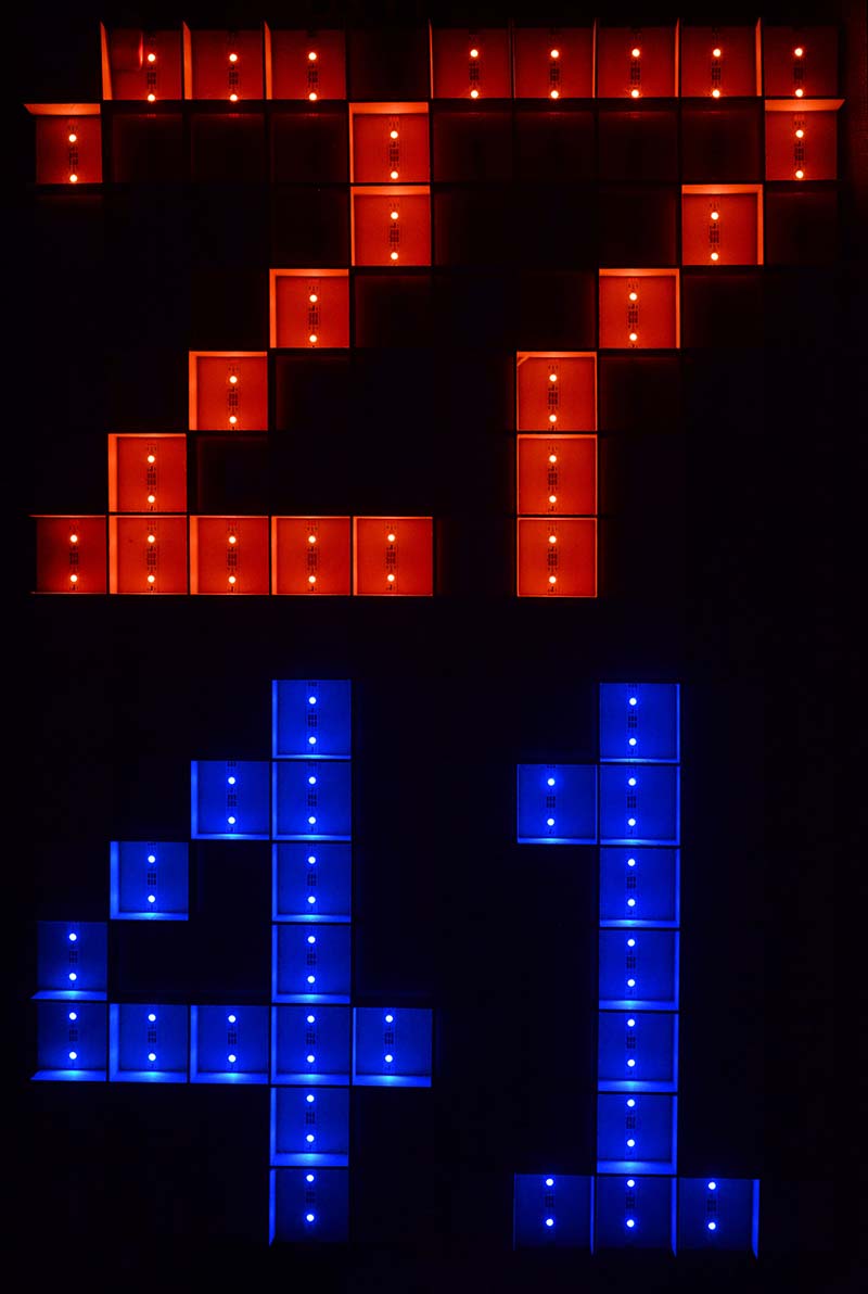
FIGURE 9. The RGB LED table functioning as a large digital clock, displaying minutes and seconds.
The complete program is available with the downloads. After the necessary values are initialized in the setup() function of the Arduino program, the main loop() function is executed, which simply reads the positions of the three toggle switches and uses a switch statement to decide what the RGB LED table will display. NV
It's possible to mount the cut strips differently with every other strip going right to left. This will reduce the length of the wires needed between strips, but does require some additional software changes. Using our 15 x 15 array example, we would calculate num with this fragment:
if (y%2 > 0)
{
num = y * 15 + x;
}
else
{
num = y * 15 + (14 - x)
}
If you want to group RGB LEDs together (as in the chess board example), these equations get more involved.
When programming the DS3231 real time clock with the Arduino Nano, here's an important point not to miss. You program the DS3231 with the rtc.adjust(DateTime(year, month, day, hour, minute, second)) function in the setup block of the program. This function includes the current time and date at your location. This will set the real time clock going in the DS3231; with the installed CR2032 backup battery, the clock will continue to run when power is removed.
Next, comment out the line with the rtc.adjust(DateTime(year, month, day, hour, minute, second)) function and program the Nano again without it. Now if you remove power, the DS3231 will continue running; when you power-up the Nano without the rtc.adjust(DateTime(year, month, day, hour, minute, second)) function, it will not overwrite the clock's current time.
Notice also that the five volt power for the DS3231 comes from the five volt output of the Nano. This allows you to plug in your USB cord to program the Nano, plus the DS3231 will be powered as well (which is convenient for debugging).
When setting the time for the DS3231, there appears to be some irregularities when setting the seconds value to 0. The minute value is off by one and the seconds is incorrect. When the initial seconds value is greater than 0, this doesn't appear to happen. There may be a bug in the rtc.adjust or DateTime portions of the code, so check your results after setting the time.
PARTS LIST
Two Five Meter RGB LED Strips, 30 LEDs per meter
Arduino Nano
Two MSGEQ7 Graphic Equalizer ICs
Mini Board with DS3231 Real Time Clock and CR2032 Battery in Holder
7413 Dual Four-input NAND Schmidt Trigger IC
Two 5.5 mm Power Jacks
Mini Stereo Input Jack, 1/8 in
Three Mini SPDT Toggle Switches
158 x 90 x 60 mm Plastic Project Box
Breadboard 3.75 x 2.875 in
Four 0.1 µF Capacitors, 6.3 or higher voltage rating
Two 0.01 µF Capacitors 6.3 or higher voltage rating
Two 33 pF Capacitors, 10 volt voltage rating
Two 200,000 ohm Resistors, 1/4 watt
2700 µF Electrolytic Capacitor, 6.3 voltage rating
1,000 µF Electrolytic Capacitor, 16 volt rating
Nine volt/one amp Power Supply, compatible with 5.5 mm power jacks
Five volt/three amp Power Supply, compatible with 5.5 mm power jacks
Miscellaneous hookup wire, solder, header pins with sockets, screws, nuts, 1/4 and 1/8 inch plywood, 3/4 x 1 inch wood strips, and wood glue.
Downloads
What’s in the zip?
Source code