In essence, this is a continuation of my previous article, “Breaking the Arduino Speed Limit” where I introduced the CA3306 fast analog-to-digital converter (ADC) and a 128x64 LCD screen to display the results. That article created so much interest that I decided to write a second article. Here, I will show the solution to the clock “glitches,” add a serial LCD screen that leaves more Arduino pins available for other things, and introduce an eight-bit fast ADC. Then, we will put it all together to make an even nicer digital storage oscilloscope.
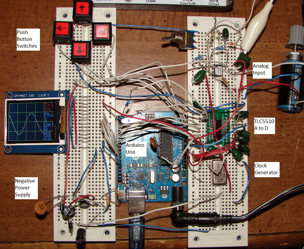
Complete scope (labeled).
The glitch problem is caused by the clock for the ADC not matching the clock for the Arduino (Figure 1). For a long time, I tried to tap into the Arduino clock on pin 9 and use that clock for the ADC. Then, I tried overriding the Arduino clock with an external clock, but that did not work either. Then, I found the solution. If you couple an external 16 MHz clock through a 10 or 20 pf capacitor to pin 9, it works! The problem is that pin 9 is used to having a very small signal on it, so the external clock has to be very small as well. This solution only works for the Arduino Uno as it is a hardware modification.
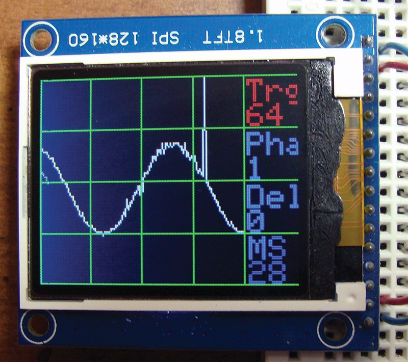
FIGURE 1. Glitch from lack of clock synchronization.
The improved clock synchronizing circuit is just a 16 MHz oscillator with a 10 pF capacitor that goes to the Arduino IC pin 9. You could also use a 32 MHz clock and divide it by two first. To be honest with you, I have also tried replacing the 16 MHz oscillator with a 24 MHz oscillator and the Arduino Uno clocked up to 24 MHz! Refer to the schematic in Figure 2.
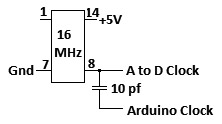
FIGURE 2. Clock schematic.
Before we get started with the ADCs, let’s change out the LCD screen for one with color and a serial interface so it will use less Arduino I/O pins. A popular serial LCD is the 1.8TFT SPI 128x160. It only needs five I/O pins with power and ground to operate.
There appear to be two versions of the 1.8 inch TFT LCD screen. One version has 10 pins and the other version has 16 pins. The pin definitions are written on the bottom of the circuit board, so it is just a matter of writing them down before you flip it over and wire it up. In Figure 3, you can see that the pins are clearly marked.
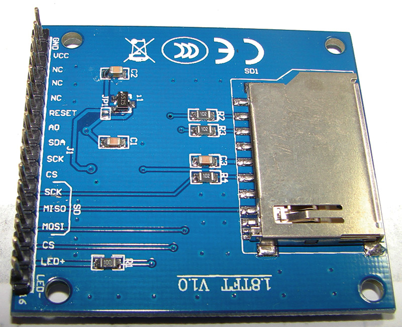
FIGURE 3. Back side of 1.8 TFT LCD.
The programs for this LCD will use the new built-in TFT drivers found in version 1.0.5 of the Arduino driver. The programs will not work without this TFT driver being properly installed. Table 1 is a chart showing how to wire the Arduino Uno to the LCD screen. I ran jumpers to connect the two grounds and 5V pins together on the breadboard.
| Arduino Uno |
1.8 SPI TFT |
| GND |
Pin 01 (GND) |
| 5V (VCC) |
Pin 02 (VCC) |
| Not used |
Pin 03 |
| Not used |
Pin 04 |
| Not used |
Pin 05 |
| D8 |
Pin 06 (RESET) |
| D9 |
Pin 07 (A0) |
| D11 (MOSI) |
Pin 08 (SDA) |
| D13 (SCK) |
Pin 09 (SCK) |
| D10 (SS) |
Pin 10 (CS) |
| Not used |
Pin 11 SD Card |
| Not used |
Pin 12 SD Card |
| Not used |
Pin 13 SD Card |
| Not used |
Pin 14 SD Card |
| 5V (VCC) |
Pin 15 (LED+) |
| GND |
Pin 16 (LED-) |
TABLE 1.
Note that pin 1 of the LCD is on the right and pin 16 is on the left as you look at the top of the LCD screen. Figure 4 is the schematic diagram of how to wire the LCD screen up.
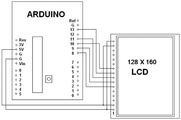
FIGURE 4. Arduino-to-LCD schematic.
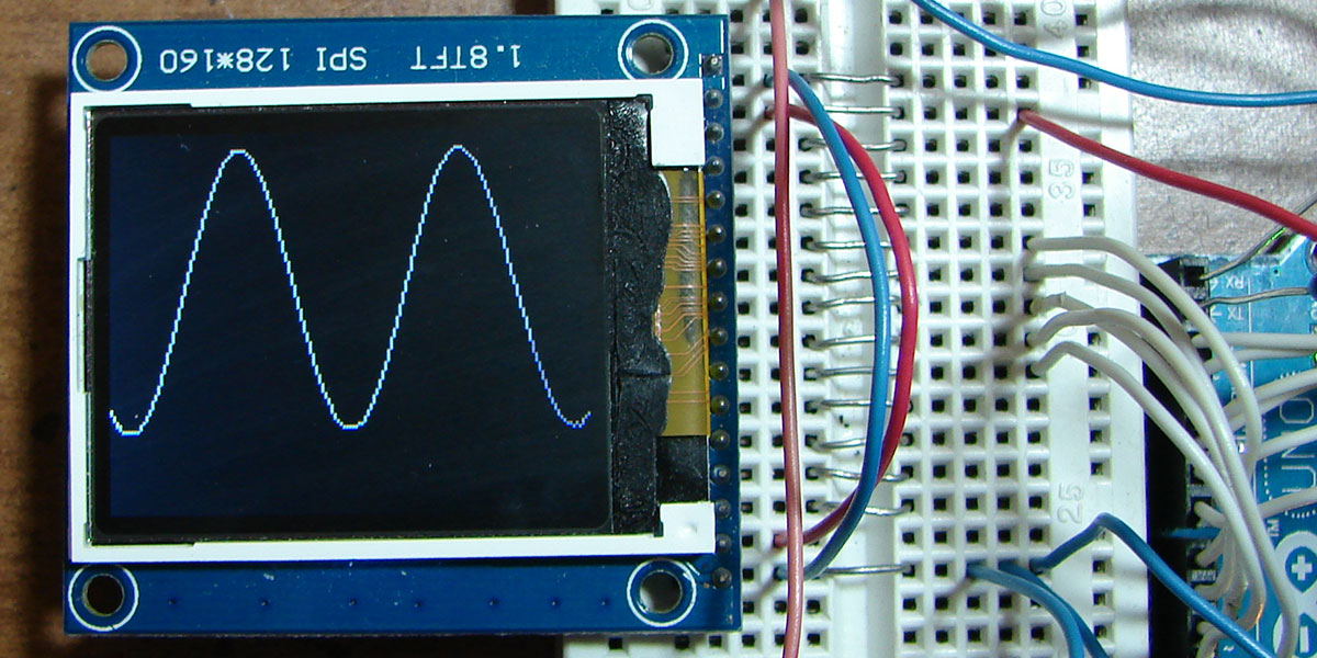
Note that D0-D7 and the six analog pins are now all free to be used for this project. We can start with a simple oscilloscope demonstration program that displays what is on A0 to test out the display. For a very simple analog input circuit, you can use a .1 µF capacitor and a 10K variable resistor to provide bias. Figure 5 shows a simple Arduino oscilloscope.

FIGURE 5. Simple Arduino oscilloscope.
This sketch produces a simple oscilloscope that is good to about 1 kHz. The oscilloscope trace is white:
// 1.8 SPI TFT Quick Oscope
// Reads & Displays the value of analog input
// on A0
// Created 15 January 2015 by Bob Davis
#include <TFT.h> // Arduino LCD library
#include <SPI.h>
// pin definitions for the Uno
#define rst 8
#define dc 9
#define cs 10
TFT TFTscreen = TFT(cs, dc, rst);
// set up variables
int Input=0;
byte Sample[160];
void setup(){
// Initialize the display
TFTscreen.begin();
}
void loop(){
// Quickly collect the data
for (int xpos = 0; xpos
<160; xpos++){
Sample[xpos] =
analogRead(A0)/8;
}
// Erase the screen to start
// again
TFTscreen.background(0, 0,
0);
// select the color red and
// display data.
TFTscreen.stroke(0, 0, 250);
for (int xpos = 0; xpos
<159; xpos++){
// draw the line (xPos1,
// yPos1, xPos2, yPos2);
TFTscreen.line(xpos,
Sample[xpos], xpos+1,
Sample[xpos+1]);
}
}
Now, let’s have some fun and add an ADC on D0 to D7. In software, the PINC parallel input command that was used in my previous article is replaced with PIND. We used the CA3306 — a six-bit/fast ADC — in the previous article, so now we will introduce the TLC5510. The TLC5510 is an eight-bit ADC. It comes in a SOP package, so you will have to use an adapter to plug it into a breadboard.
Note that the TLC5510 outputs now go to D0 to D7 of the Arduino. You will need to either disconnect D0 and D1 in order to update the software on the Arduino or use two 1K ohm resistors as shown in the schematic. These same D0 and D1 pins are always used for the Arduino to communicate over the USB connection. However, this is the only way to get eight bits in parallel into an Uno.
Here are some fast ADCs that are all somewhat “interchangeable:”
- The TLC5510 is eight-bit at 20 million samples per second.
- The TLC5540 is eight-bit at 40 million samples per second.
- The ADC1175 is eight-bit at 20 million samples per second.
- The ADC1175-50 is eight-bit at 50 million samples per second.
Figure 6 is the TLC5510 schematic diagram. Note that pin 1 is at the bottom, so the IC is being drawn upside down.
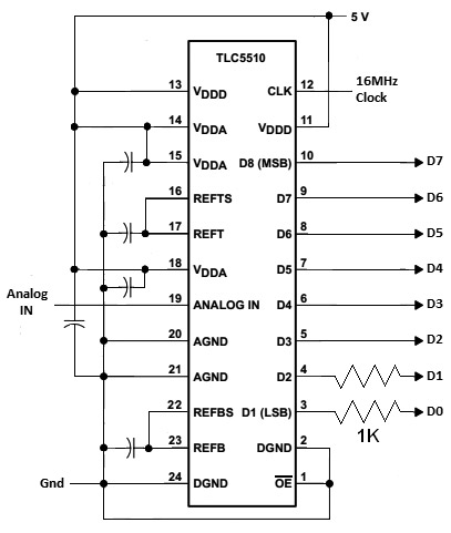
FIGURE 6. TLC5510 schematic.
I wired it up upside down to match the schematic and then spun the breadboard around to hook it up. The capacitors are all .1 µF at 16 volts.
Figure 7 shows the TLC5510 wired up and running. In this photo, you can also see the 10 pF capacitor going from the clock to pin 9 of the Arduino Uno.
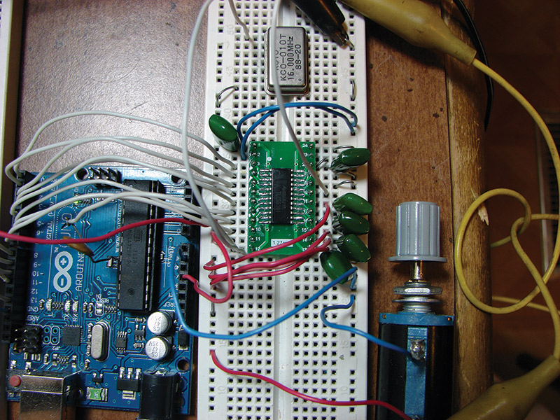
FIGURE 7. TLC5510 wiring.
Now to put some of those free analog input pins to work. You can connect four momentary contact switches to A2 to A5 to select up, down, right, and left. Up and down will select the item to change, and right and left will change the values of the selected item. You could put all four switches on one analog pin by having each one select a different voltage. Figure 8 shows the switches schematic.
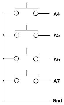
FIGURE 8. Pushbutton switches schematic.
Next, we will improve on the analog input section that we saw in the last article. In the previous design, when you changed the gain of the op-amp, the bias changed and had to be re-adjusted. It is better to not have an adjustable gain to avoid this problem. This change will even make the analog input section simpler to design. You can use a TL082 IC instead of the LF353 for the dual op-amp.
The “bias” control provides a bias to the ADC. You will need a bias of about 1.3 volts as 2.6 volts is the maximum input. The 1.3 volts then becomes the “zero” position in the middle of the LCD screen. This bias is the 0 signal since the ADC uses 2.6 volts as its maximum input voltage and does not allow any negative input voltages. Figure 9 shows the analog input schematic.
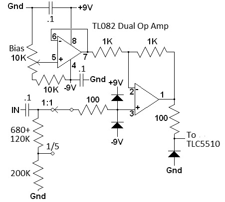
FIGURE 9. Analog input schematic.
Figure 10 is a photo of what the analog section looks like. Do not forget the .1 µF filter capacitors near pins 4 and 8 of the op-amp. These capacitors will make a huge difference in the amount of noise. I left out the protection diodes for now, but they will need to be there for real world situations.
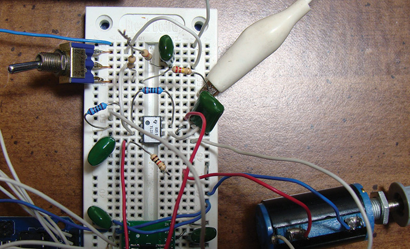
FIGURE 10. Analog input wiring.
For a -9 volt source, you can use a 9V battery or (even better) use a 555 oscillator with two diodes to form a simple power inverter. Figure 11 is a schematic for a 555 inverter.
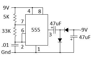
FIGURE 11. Negative power supply.
The diodes can be a 1N4001 or similar. Under load, the output is only about -5 volts, but that works fine.
Last of all, there are many software improvements. We can now switch between multiple selections like the delay between samples (as before), the trigger level, and the trigger phase.
Another software improvement is that the trigger is now very “solid.” It first checks for a positive-going signal, then for a negative-going one. Otherwise, it might just catch the positive level anywhere and proceed to collect samples:
// wait for a positive going trigger
if (trigphase==1){
while (Input < trigger){
Input = PIND; }
while (Input > trigger){
Input = PIND; }
}
The future possibilities are endless. There are three pins still available on the Arduino: D12, A0, and A1. They could be used for logic analyzer inputs, or for additional analog inputs of just about anything that you can imagine. The free pins can even be used to control a FIFO memory IC that can increase the sample rate to 50 MSPS (Million Samples per Second) or even faster. NV
Downloads
What’s in the zip?
Source Code