Several months ago, our toilet ran for several hours because the flapper didn't seat properly and we didn't hear the water continuing to run. Since I had recently built a couple of projects using PIC processors, I thought I would try to build what I call a Toilet Sentinel.
For those of you who have or are interested in home automation, header H2 is a bit-banged serial port. It is fixed at 300 baud, eight data bits, and two stop bits. The only signaling which has been implemented is that of the normal flush operation:
- “E” for start of flush
- “I” for end of flush
- “P” for problem
For instance, this signal could be connected to a ZigBee transmitter which transmits to your home automation system.
In reviewing the various PIC processors, I wanted one with as few pins as I could get which would meet my I/O requirements. I also wanted one which had very low power consumption so it could run from a single cell for at least a year. I finally selected the 12LF1572.
This is an eight-pin device with low current drain — about 10 µA when idling using its 31 kHz internal oscillator as the CPU clock. My previous projects used PICs from the 18 series which has non-paged I/O and RAM, so I was a little skeptical about the paged memory in the 12 series devices. The paged I/O did “catch” me a few times, but it was not too difficult.
There are fewer instructions in this PIC as compared to the 18 series, but the only ones I really missed were the conditional branches. It was sometimes confusing using the skip operations, but as long as I documented the code properly I managed okay.
In looking over the code, I still sometimes do a double-take when I see a skip instruction followed by one or two GOTO statements. Also, even though the clock frequency is 31 kHz, the instruction execution time is about 8 kHz. If you want to do some debugging, be aware that single stepping takes about 20 seconds per step.
I gave a lot of thought to finding the most cost-effective method of detecting the water level. I probably spent more time on this effort than any other phase of the project. At first, I was gong to use a commercial water level sensor; however, the units I found turned out to be too expensive for my purpose. The sensor I decided upon is simply two parallel wires terminated with gold plated contact pins (see Figure 1).
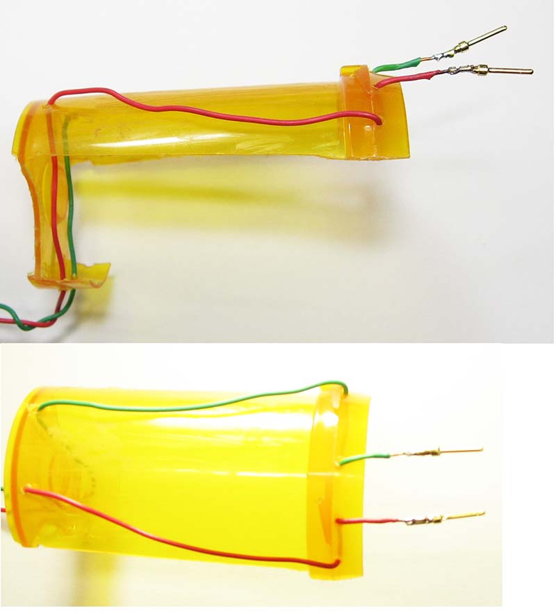
FIGURE 1. Two views of the sensor showing the pill container as cut with a Dremel tool. The top photo shows a small lip which allows it to hang quite nicely on the back of my tank.
I initially used the wire ends stripped back about 1/2”. However, after about a month, there was enough oxidation on them that they stopped working. The gold plated pins will last a lot longer. I used some gold plated “D” connector pins which I happened to have in my stock of parts. If you want to get a little more robust, you can use stainless steel bolts instead.
These two pins and the water between them form a switch which is “closed” when the pins are submerged. As you can see from the schematic, the circuit is very simple and has very few components. I purchase most of my parts from Digi-Key.
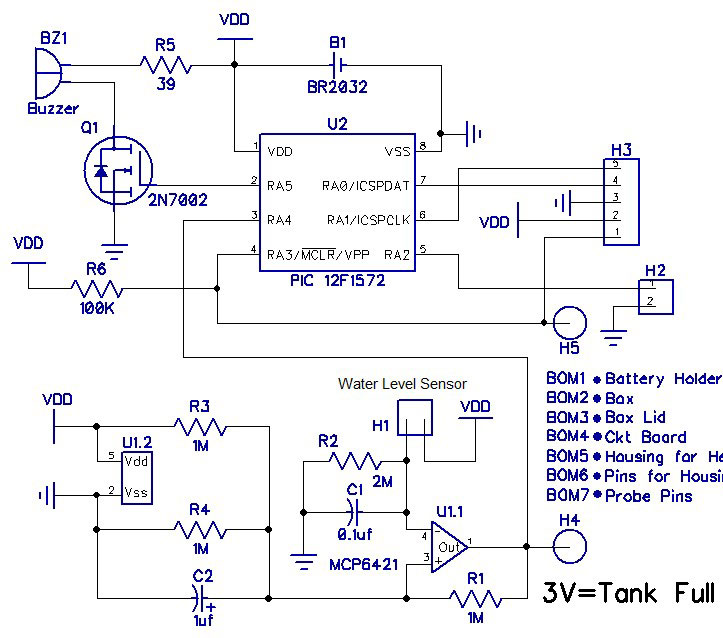
Schematic.
The printed circuit board (PCB) is approximately 1” x 1.35” and fits easily into a low cost “potting” box (see Figure 2).
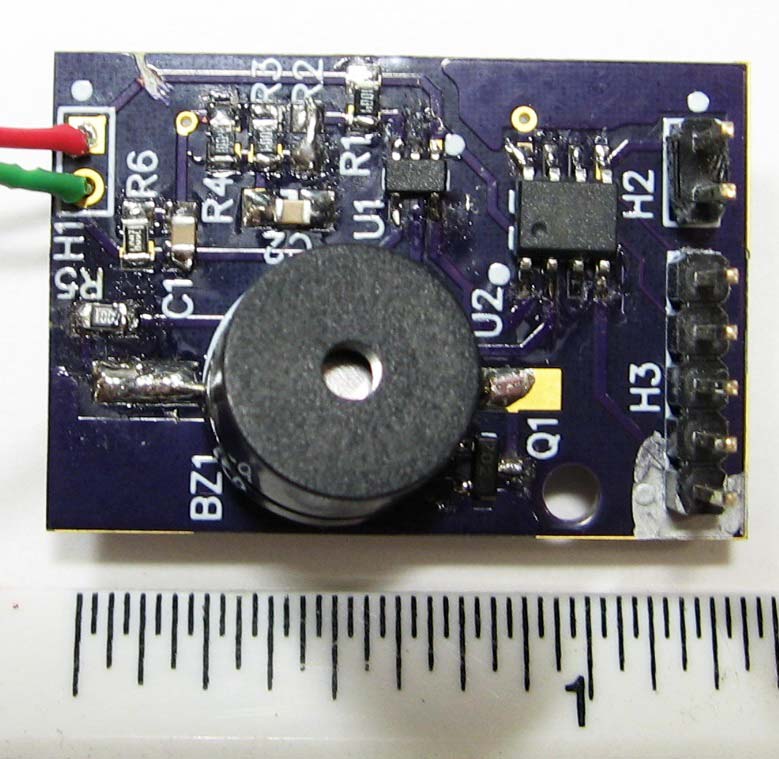
FIGURE 2. As you can see, the circuit board is quite small. The battery mounts on the bottom side and is kept in place by the battery holder.
System Operation
The operation of the system is quite simple. When the unit is first powered up, it goes through a calibration cycle requiring you to flush the toilet once. It measures the amount of time between when the water drops below the level of the sensors to when the sensors are submerged again. This time — plus a 25% pad — is used as the basis for determining whether or not future flushes finish on time.
If the system detects that too long a time has occurred before the tank becomes full again, a warning signal is sounded via an audio transducer (buzzer).
The op-amp is used as a switch buffer and inverter with hysteresis. The amount of hysteresis is dependent on the values of R1, R3, and R4. Using Kirchhoff’s Current Law and the feature of an ideal op-amp of infinite input resistance, the equation for the voltage at pin 3 of the op-amp is:
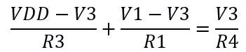
If R1, R3, and R4 are equal, the formula reduces to:

where V1 is the voltage at pin 1 and V3 is the voltage at pin 3. The voltage on the output pin, V1, will be either VDD or ground; therefore, V3 will be either 2*VDD/3 or VDD/3. With a 3V battery, these voltages will be 2V or 1V, yielding a 1V hysteresis band.
Note that if you want to measure the voltage divider value at pin 4, you need to take into account the input resistance of your voltmeter since most are 10 megohms and R6 is 3 megohms. The voltage at pin 4 must measure at least 1.81V when the probes are submerged if you are using a voltmeter with a 10 megohm input resistance.
When there is water between the sensor pins, the circuit is “on” and the voltage at pin 4 will be high: >2V. This will cause the output voltage to go low: 0V. When there is no water between the wires, the circuit is “off” and the output voltage will be high: 3V. The program in the PIC recognizes these voltages as “tank full” and “flushing,” respectively.
As you can see back in Figure 1, the sensor assembly is rather simple. I used a plastic pill bottle I had laying around and cut it using my Dremel tool. I sectioned the bottle so that it hooks over the edge of the tank. I drilled several holes in the bottle where I ran the sensor wires so that they stay in place.
The buzzer is used during both normal operation and calibration. The program uses a series of long (300 ms) and short (100 ms) beeps; some are Morse code characters to indicate several states:
Calibration signals:
Short, long, short = R: Program Running
Short, short, long, short = F: Initiate a Flush
Battery Check
Sound the number of seconds in binary (see text below)
Short, long, short, short = L: Flush Time too Long (>192s)
Normal operation signals:
Battery Check
Short, short = Flush Complete
Short, long, long, short = P: Problem
Battery check:
Short = Battery OK
Long, short, short, short = B: Battery Low
At the end of the calibration cycle, the number of seconds the system measured is sounded by the buzzer. The beeps starts with the most significant “1” in the binary value, so the first beep is always a long. For example, a value of 60 (b0011 1100) seconds would be represented by: long, long, long, long, short, short. A single short is used for the battery OK signal because it saves on the battery.
The buzzer uses one of the PWM channels set to divide the CPU clock frequency by 16, yielding close to 2 kHz. This is quite close to the resonant frequency of the buzzer which is specified as 2,048 Hz ±500 Hz.
In order to minimize power drain, the PWM channel is enabled only when the program needs to generate a beep.
A battery check is done at the beginning of every flush cycle. The A/D converter in the PIC is used to measure the FVR (Fixed Voltage Reference) of 1.024 volts.
Since the A/D uses VDD as its positive reference, whenever VDD drops below 2.048V, the FVR will measure over 1/2 scale. All the program does is look at the most significant bit of the A/D conversion. If it is on, then the battery voltage is low and the program sounds the “battery low” signal.
When you first insert the battery, the program forces a calibration cycle. You will first hear an “R,” to indicate that the program is Running. Then, you will hear an “F” which is a Flush request. Once a flush is detected, a battery test will be performed so you should hear one short beep. When the tank has refilled, you will hear the number of seconds it took to fill as described above.
You can force a reset by shorting pins 1 (/MCLR) and 3 (ground) of H3. The /MCLR signal is also on H5 which is 0.1” from H1 pin 3. This allows you to use a small screwdriver to short the pins to force a reset. Note that if you power the unit before inserting the probe into the tank and /MCLR is not grounded, the program will detect that a flush is in progress.
The circuit draws less than 20 µA continuously; however, I used that value in my calculation for battery life. The buzzer device draws about 50 ma for 150 ms (300 ms with a 50% duty cycle) for each normal flush cycle — assuming no problems.
These values yield 480 µA-hours/day of continuous current, and about 83 µA-hours per day for the buzzer — assuming 40 flushes per day. The sum of these two values divided into the 0.25 amp-hour rating of the battery yields about 443 days of operation.
The source code for the program is available with the downloads. All my design files are there as well.
I usually use DipTrace (www.DipTrace.com) for all of my PCB designs. However, recently, I've been using OshPark (www.oshpark.com) for my circuit boards.
A Few Assembly Notes
None of the three headers are absolutely necessary. You should solder the leads from the sensor directly into the holes where H1 would be installed since the box is not tall enough to accommodate the mating housing
If you're not going to program the PIC on the PCB, then H3 is not necessary. If you do want to use the headers, the part numbers and quantities in the Parts List have enough pins for all three headers. You simply need to cut them to size.
Although a crimper makes the job of assembling the pins for the housings easier, it's not required. Before I got a crimper, I used a pair of small needlenose pliers to crimp the wires to the pins. It took a little practice (with several failures), but I did learn how to do it.
Take a look at Figure 3 for a sample of what the housings and pins look like.
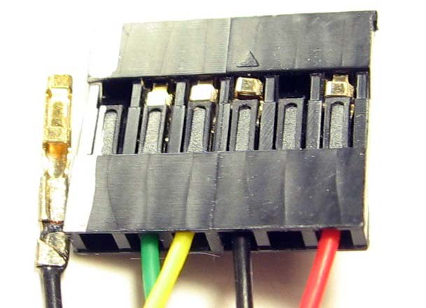
FIGURE 3. Close-up of a sample header which I use for programming my PICs.
The op-amp used in the circuit is in an SOT-23-5 package. The spacing between pins 1, 2, and 3 is 0.95 mm (0.037 in). I highly recommend that you work using a lighted magnifying glass and a very fine soldering iron tip and fine solder. My iron has a 0.8 mm tip and I use 0.015 in diameter solder. The spacing on the other semiconductors is not nearly so close.
I recommend a good pair of tweezers to hold the parts in place while soldering. I generally apply solder to one pad on the PCB and then place the component while heating that same pad again. Then solder the remaining pad(s).
There is a sizable pad on the bottom of the board for the negative surface of the battery — you should apply a smooth covering of solder to ensure good contact.
Although there is a mounting hole in the PCB for a 4-40 bolt, I leave the PCB floating and use a rubber band to hold the lid onto the case.
Note that the buzzer is polarized. The PCB silk screen shows which terminal is the positive. Also, you will need to bend the leads in order to surface-mount it.
I filed a notch in the lid for the sensor wires and drilled a hole in the lid to allow more sound out.
CAUTION: There is no protection against polarity inversion! Please be sure to insert the battery with the negative side against the board.
I hope you find this circuit as helpful as I do. NV
Parts List
| Ref/Des |
Value |
Part Number |
Qty |
| B1 |
CR2032 |
P189-ND |
1 |
| BOM1 |
Battery Holder |
BAT-HLD-001-ND |
1 |
| BOM2 |
Box |
377-1692-ND |
1 |
| BOM3 |
Box Lid |
377-1693-ND |
1 |
| BOM4 |
Circuit Board |
See text |
1 |
| BOM5* |
Housing for Headers |
WM5341-ND |
1 |
| BOM6* |
Pins for Housing |
WM2562CT-ND |
10 |
| BOM7 |
Probe Pins |
609-1474-ND |
2 |
| BZ1 |
Buzzer |
668-1097-ND |
1 |
| C1 |
0.1 µF |
311-1335-1-ND |
1 |
| C2 |
1 µF |
1276-1119-1-ND |
1 |
| H1,H2,H3* |
Headers |
S1012EC-20-ND |
1 |
| Q1 |
2N7002 |
2368-2N7002-ND |
1 |
| R1,R3,R4 |
1M |
311-1.00MCRCT-ND |
10 |
| R2 |
3M |
311-3.01MCRCT-ND |
1 |
| R5 |
39 |
311-39.0CRCT-ND |
1 |
| R6 |
100K |
311-100KCRCT-ND |
1 |
| U1 |
MCP6421 |
MCP6421T-E/OTCT-ND |
1 |
| U2 |
PIC12F1572 |
PIC12F1572-I/SN-ND |
1 |
* These parts are only necessary if you are going to use the headers and mating housings.
Downloads
What’s in the zip?
DipTrace Design Files
Source Code
Battery Life Calculation Spreadsheet