Browsing in a craft store, I happened on a box that looked like a small book. I thought it would be cool to see if I could put enough electronics in it to make the cover pop up as a Halloween prop. As with most of my projects, that concept was just the beginning of a small project that became a larger project due to scope creep. I would always think — wouldn't it be even cooler if I did this ... and then that!
This is really a fun project. Even though it took six prototypes, I enjoyed every minute of the design/construction process.
With all the Halloween props on the market, it’s difficult to startle people. I use the word startle because ‘scare’ is now a multi-million dollar Hollywood thing. In this project, you can build a little book that startles people.
A good Halloween prop needs a “hook” to pull people in; a visual to keep them interested; then a “shock” to startle them. This project has all three: a hook (muffled sound) pulls the victim in; a visual (an eye moving left to right) keeps things interesting; and then there’s a make you - jump finale — all in a small 5 by 7 inch book. I have tested the effectiveness of this little book in my wife’s gift shop (I didn’t scare any little old ladies — I swear!). Although I didn’t video any of the reactions, they were video-quality startles.
What Exactly Does It Do?
It’s a small, odd, old-looking book — with an eye and eyebrow. It sits quietly on a surface. It then makes a weird muffled laughing sound. The victim hears the sound and walks up to investigate. Nothing happens. No, wait! Did that eye move? They look closer, reaching out to open the cover of the book — Yikes!
It just jumped at the unsuspecting mark several times, opening and closing its “mouth.” The book then retreats to assume its passive-aggressive demeanor — for the next victim.
All of this is initiated by you. A four-channel remote secreted in your hand controls all the timing and functions. Those functions are:
Channel 1. Sound from module
Channel 2. Eye moves
Channel 3. Book hops forward rapidly
Channel 4. Book hops backward rapidly
Let’s Get Started
There is no microprocessor or programming in this project. The system utilizes a double-sided PCB (printed circuit board), an L293 quad bridge, two regulator ICs, an off-the-shelf four-channel transmitter and receiver, two motors, and a sound module similar to the ones you find in a greeting card. This project is powered with a standard nine volt battery, so it is safe for everybody. Most of us electronics nerds have saved those little sound modules from greeting cards, but if you don’t have one, you can just leave it out of the project or head to the dollar store.
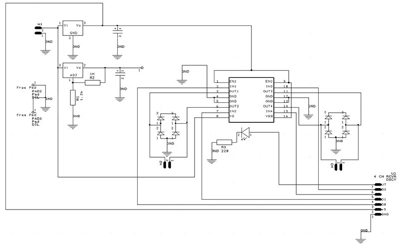
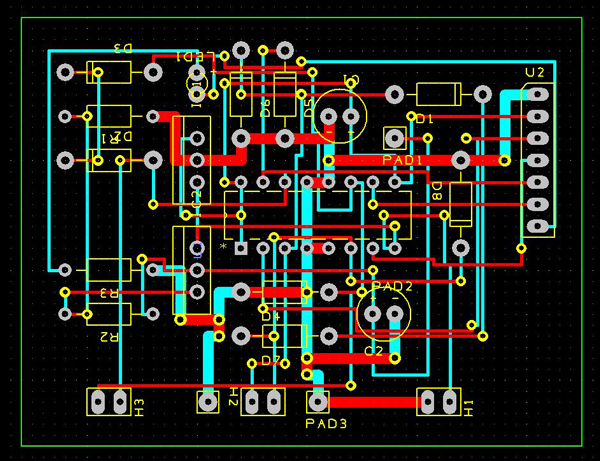
The brains are on a double-sided thru-hole PCB. Figures 1 and 2 are the schematic and board.
FIGURE 1. Schematic.
FIGURE 2: Double-sided printed circuit board.
Keep this board as small as you can. The inside of this little book is crowded. Pay attention to the location of each part with relation to the moving parts, and make sure they don’t interfere with each other or with the closing of the book.
For purposes of this article, we will assume that the book is in the same orientation as if you were getting ready to read it. Cover opens right to left.
It’s best to wrap the book with an “old” looking book cover first. Get some brown craft paper (grocery bag!) and cut it big enough to wrap the cover, back, and spine of the book. Then, wad the paper several times to get a good wrinkle in it. Glue it on the book avoiding the fake pages. Spray adhesive works well. (Spray the paper, not the book.) I make the paper wrap over the edges for a neat look.
Let it dry for a couple hours, then you can highlight the wrinkles with some dark brown paint on a dry brush. Go lightly or the whole thing will just be a solid color. The secret here is to wet the brush with paint, then paint a paper towel until the brush ALMOST runs out of paint. Then, LIGHTLY go over the wrinkles. When you have the look you want and the paint is dry, a coating like Mod Podge or watered-down white glue can be painted to cover the entire book for better longevity.
On the back cover (the bottom) of the book, cut a 3/4” wide slot in the center — left to right — all the way through the cardboard, leaving only a 1/4” of cardboard on the left and right sides. This is where the book gets its locomotion.
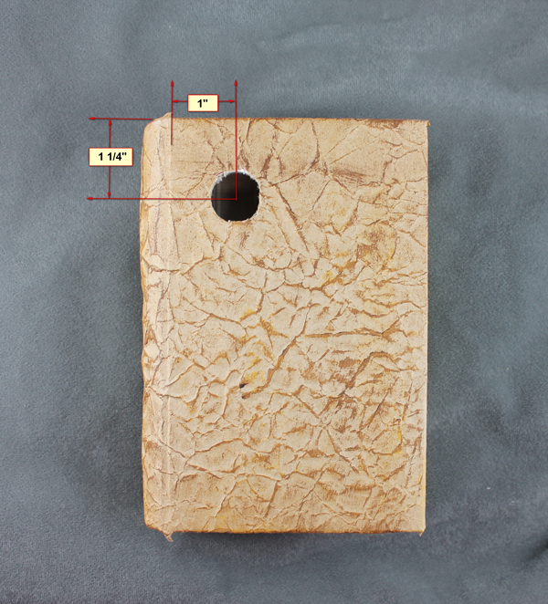
Drill the eye socket with a 13/16” drill bit. I used a Forstner bit. The placement of this hole is critical so that the eye mechanism doesn’t rub on the 600 RPM motor mount. After a lot of trial and error, I determined the best placement is in the upper left corner of the cover, 1-1/4” from the top, and 1” from the spine (where it bends). Refer to Figure 3.
FIGURE 3. Eyeball placement dimensions.
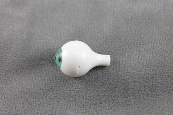
Drill the plastic eye with a 1/16” drill bit close to the mold mark all the way through to the other side. I drill each hole separately (since the eye is hollow) to make sure they are perfectly aligned. Turn it 90 degrees and drill close to the end of the ‘stem’ as shown in Figure 4.
FIGURE 4. Drilled 20 mm eyeball.
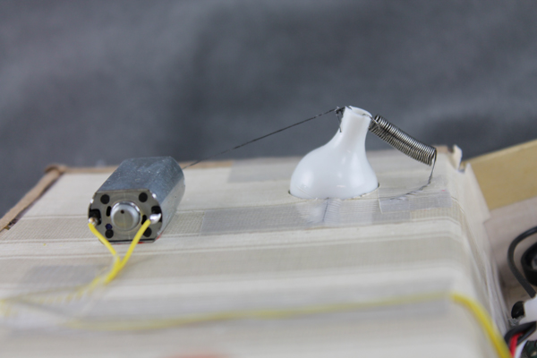
Place the two inch piano wire through the first holes creating a hinge point. Place the eye in the hole and tape the wires on both sides with filament tape so the eye can look left to right. Take the FF-030 motor and carefully (gel) super glue it adjacent to the eye so that it does not interfere with the 600 RPM motor. Be careful that the super glue doesn’t enter the motor, or you will have a paperweight and need to buy a new one. Tie a surgeon’s knot with the thread (I used Fireline — strong stuff!) onto the end of the motor shaft and put a tiny spot of gel type super glue to keep it from slipping. Tie the other end of the thread to the end of the eye stem. Attach a weak spring as shown to pull the eye back after the motor has deenergized. This is a lot of commotion to get the eye to move — but it’s worth it. Color the eye if you want and hook the motor up for a test. Fiddle with it, restring, fiddle — done (Figure 5).
FIGURE 5. Eye motor detail.
Drill the center of the aluminum bar all the way through with a 3 mm drill bit. Then, turn it 90 degrees and drill a setscrew hole (#43 drill bit) for the 4-40 setscrew. Tap the setscrew hole and mount the bar on the 600 RPM motor. You now have a “propeller.”
On each end of the propeller, put some Sugru or Oogoo for traction. Once dry, mount the motor so that the propeller is central in the slot. I used a 3D printer to make the plastic motor mount (see downloads), but wood or cardboard will also work. Just make sure it is secure and doesn’t interfere with the eye.
After populating the PCB and attaching all the external parts (Figure 6), place the PCB inside the box to the lower left as far as possible.
FIGURE 6. Populated and wired PCB.
Use foam tape to hold it in the box. The LM317 regulator is to output the voltage your sound module needs. Only two resistors are required to get the proper voltage. The schematic is set up for 2.9 volts. See the LM317 datasheet for the proper resistors if yours differs from 2.9V.
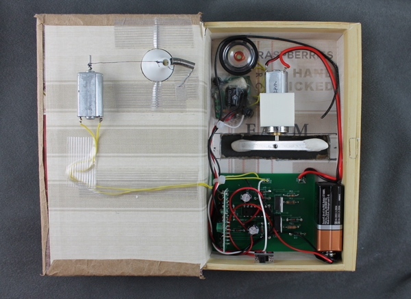
Route the wires to keep them away from the propeller. Mount the slide switch just below the “pages” for easy access. Put some Velcro™ on the side of the battery and mount it in the slot beside the PCB. Mount any sound module on the other side of the prop motor. Be careful to keep it away from moving parts. Refer to Figure 7 for the parts placement.
FIGURE 7. Book parts placement.
Operation
Wait for an unsuspecting victim. Remember, Channel A is for sound. When they come over to look, Channel B is for the eye movement. People are curious. They will normally reach to open the book. Timing is everything here. Use Channel C or D to make the book jump at them, then retreat. Awesome!
If you like Halloween and scaring (or startling) people, then this is for you! NV