During the ‘50s, ‘60s,’70s, and well into the ‘80s, capacitor and resistor substitution boxes were very popular pieces of test equipment (TE). Almost every repair shop and research lab had a collection of these devices. Now that we are in the “digital” age, they seem to have lost favor as a desired piece of test equipment. You just don’t hear much mention of them anymore. I’m not sure why this came about, other than the fact that they are such simple devices. Folks may have the feeling they can easily do without them.
I acquired several of these boxes years ago, and still use them frequently today. They can be real time savers for things such as “homing” in on exact values beyond the initial design stage calculations, and for unknown or uncertain values that you need to plug into an existing design. They also can be very useful for troubleshooting procedures. Last but not least, they are very quick and easy to use.
Back when these boxes were quite popular, they were very reasonably priced and affordable by anyone — including hobbyists. Today, it’s a different story as even a basic box that has decent accuracy, range, and voltage ratings are too expensive to justify their cost. A box such as this might start at $300 or $400. I have seen some boxes from China on eBay for well under $100 with some decent specs. However, I did have the opportunity to see the internals of some and it left me a bit suspicious about them.
For starters, the switching was done by all plastic miniature BCD rotary switches which were PCB (printed circuit board) mounted only (no shaft to panel attachment). These boxes take a lot of hard switching over their lifetime, so this leaves me doubtful about their mechanical longevity. I cannot speak for all of them; only the ones I have had the opportunity to tear down. SparkFun Electronics has a starter kit (resistive) that has nice specs, and from the pictures they show it looks to be of decent construction and at a very low price.
Start working your way up in tighter specs, and substitution boxes can run over $1,000.
The very top of the heap can go for upwards of $30,000! Of course, these boxes have specs that would rival primary standards, and are way beyond our needs or even our capabilities to make use of them. By contrast, the boxes I purchased years ago are five decades of value, 1% accuracy, and 600 volt/one watt ratings, and cost well below $100 in today’s dollars. Plus, they all still meet factory specs.
Types of Boxes
Resistor and capacitor boxes come in two basic styles — one being a hit-and-miss selection of standard values, which are the cheapest and least useful. The other is in decade values which will cover four, five, or six orders of magnitude in range, with a resolution of the lowest decade range (i.e., lowest range of 100 pF — steps in 100 pF to the largest value of the box — and lowest range of 10 ohms — steps of 10 ohms to the largest value of the box).
Of these types, the only one I would consider is the decade style due to its wide range and almost infinite resolution (based on the lowest decade range). Just imagine that a seven decade box can cough up 10 million values of resistance in one ohm steps!
Substitution boxes are still being manufactured and are available through most retailers. They come in a variety of electrical switching schemes such as digital, rotary, and slide switches. The thumbwheel switches are of modest cost, and will be either in straight decimal or BCD format. (The decimal type requires nine component values per switch, while the BCD type will only require four component values.) Each switch covers one decade of values (0-9) that are stacked side by side. They will read out in numerical values for each segment. When all are set, they will give a direct readout of the total value such as 0.241200 µF or 520,970 ohms. However, their voltage ratings are 50 VDC or at best maybe 100 VDC, and low wattage.
This limitation may be of no concern to you, but if it is and you desire higher voltage and/or wattage, you definitely have to go with the rotary style switching or slide switches.
When using the rotary switch type to accommodate higher wattage/voltage components, it can become very pricey as the voltage and value ratings increase. Each switch will cover 11 positions: a full decade plus zero (0-10). This type offers good ergonomics and speed of switching. Then, comes the slide switch style; these are the lowest cost version of the switching schemes.
This configuration will have four individual switches per decade: either in a 1-2-3-4 sequence, or a BCD format with a 1-2-4-8 sequence. The panel is usually arranged as four vertical switches which covers one decade; the value is numerically labeled as the numbers just explained. Then, each decade just repeats in a horizontal direction.
So, if it has six decades of range, it will require 24 slide switches (four values times six ranges) with each decade labeled in the same sequence, but with higher multipliers. By adding up all the switch values that are engaged, you come up with a total value.
These switches have the advantage of high voltage and a cheap selling price. However, after using one of these on several occasions, it almost drove me nuts trying to keep track of adding and subtracting numbers constantly (1-4 per decade) to obtain the actual value. They also require a lot of panel machining for rectangular slots and mounting holes.
The Internet has a lot of info on constructing these boxes but — as usual — it tends to be hit-skip information without much mention of advantages/disadvantages about their operation and usefulness. What I want to describe in this article is various types of DIY construction of all the various switching modes, along with the benefits and caveats of each type. I will only cover the basics of construction and leave it up to the builder as to enclosures, knobs, etc., to suit his/her fancy.
The Resistance Decade Box
Let’s begin with resistor sub boxes since these will be by far the simplest and cheapest. We will look at this in three different switching schemes: digital, rotary, and slide switches.
Starting with the digital switch, the type needed here is a decimal version (not BCD). Refer to Figures 1 and 2 for a wiring diagram and a completed switch with components installed for any one decade. Note that physical pinout locations may vary according to manufacturer.
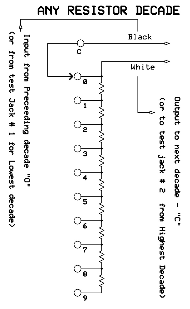
FIGURE 1. Digital switch schematic.
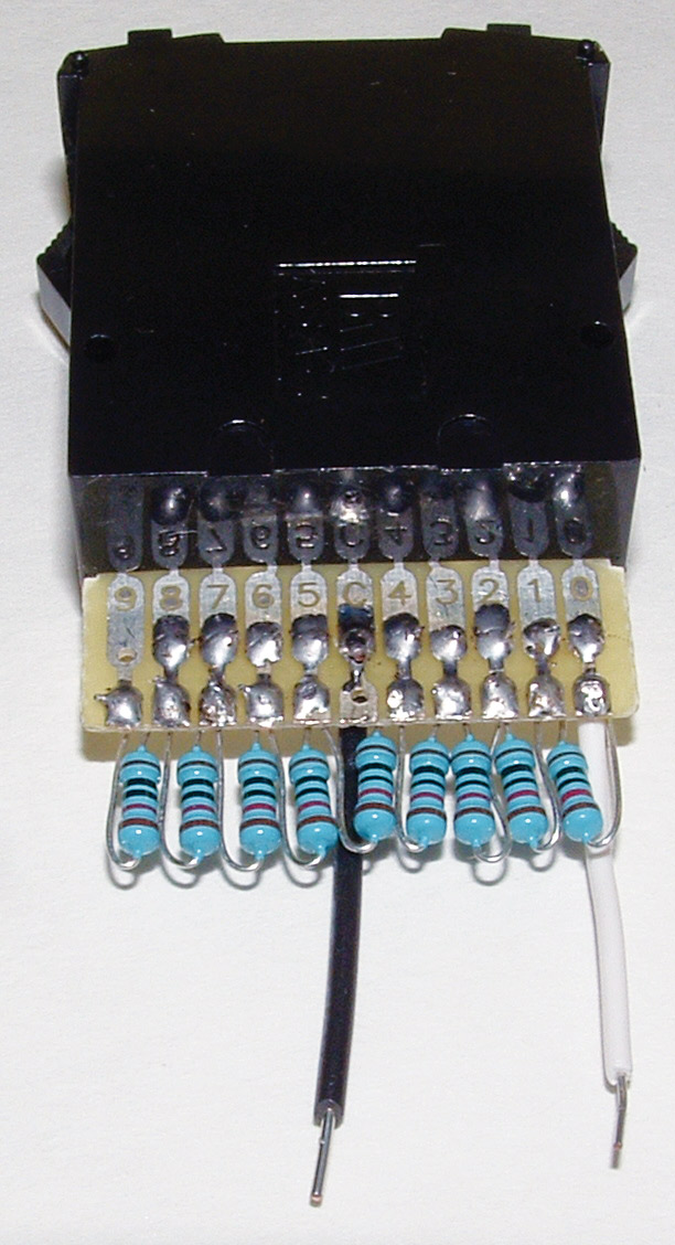
FIGURE 2.
The pin arrangement of the one I used is fairly common, in a 9-8-7-6-5-C-4-3-2-1-0 from one side of the board to the other. Each switch section will output a 0-9 value of its particular decade value. Then, the switch sections are stacked and interlocked side-by-side to complete the unit. You can go as high or low in decade units as desired, but I have found that six decades in 10s, 100s, 1Ks,10Ks, 100Ks, and 1Ms should be quite sufficient.
I have very rarely needed any value outside of that range, and inherent wiring and contact resistance degrade the 1s decade. However, a 1s decade does have some merit in that the overall readout would be in total ohms and eliminate the need to mentally add a zero after the last digit. Alternatively, one could just add a “dummy” section in that slot and lock it down to “0” (assuming the succeeding decade was 10s).
Most digital switches have an upper limit of 50 VDC or at most 100 volts, and lower current ratings to boot. If that will meet your needs, then you can use 1/4W resistors or possibly 1/2W on the 10s or 1s decade to accommodate higher currents on these ranges (although space is at a premium here). To make this unit ultra small, SMD components really shine here. One percent SMDs are not hard to find, but as they go up in wattage rating, the job gets a little tougher.
As to accuracy, you can get by with 5% tolerances if you’re not too fussy. In my experience using 5% carbon film, their tolerance is almost always within 2-3%. Fortunately, 1% is not priced much more than 5%. You will need nine resistors per decade, so you will be looking at 45-63 components and the difference in price between the two might be $3 at the most.
The upside of this style of construction is very compact boxes, a digital display of the total resistance dialed up, and a low parts cost. The downside is (as mentioned) limits of voltage and power ratings. I used 1/4W/1% resistors in this one, and the populated switch shown cost me $0.82 per decade. Add $5 for a box and the total cost was about $10.
Next up is the rotary switch style. Refer to Figures 3 and 4 for a wiring diagram and a completed switch with components installed for one decade.
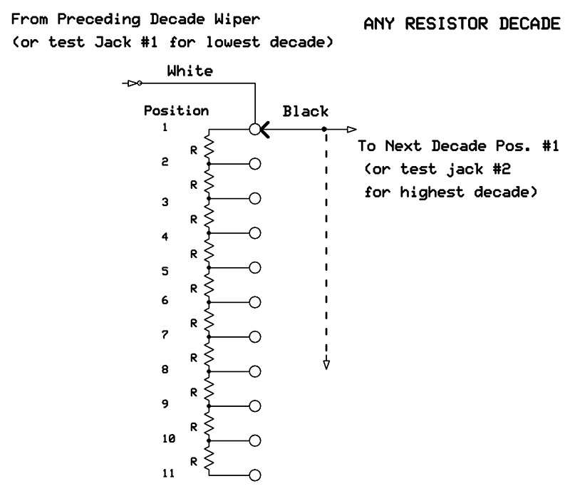
FIGURE 3. Eleven position rotary switch schematic.
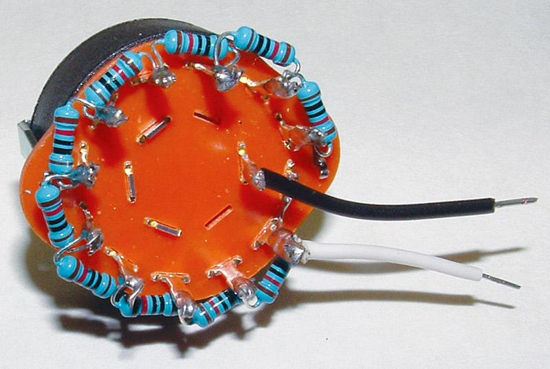
FIGURE 4.
The desirable contact arrangement here would be single pole/11 position. This would allow for 0-10 values per decade, and it is convenient to have that extra value (10) when in actual use. However, most of these switches will be 12 position with an occasional 10 position.
If 10 position is the only one available to you, then the arrangement can be 0-9 values per decade. With 12 positions, you could do the switching sequence in a 0-10-0 value. The zero on each end of the switch is not totally undesirable, and occasionally speeds things up when rapid firing through the decade ranges. Or, you could just bury that extra position with double zeros at the onset of switching.
A word of note here is that some rotary switches come with a removable position stop allowing you to limit the maximum position to whatever you want. If you have a choice, get the “make-before-break” type of switching. This will ensure that the circuit area you are using it on will never see a momentary open condition when switching in the different resistor values.
However, opening “live” circuits momentarily in most cases will not have much effect on them, but some thought will be required for the consequences of that stage and the circuitry downstream from it. For those occasions where you are in doubt, you can momentarily power-down between switching in different values.
In the switch shown, I used only 1/4W resistors for better illustration. In the actual completed unit, I used 1/2W on the upper ranges and 1W on the lower ranges — all 1%. I also went with a 12 position switch because I could not pass up the price. This is a make-before-break switch and has no stop, which is kind of neat since you can run through the positions in either direction no matter what location it is on. The cost per populated decade switch averaged $1.30. Total cost for six decades, box, and knobs was about $18. The completed unit is shown in Figure 10.
The upside of rotary switching is higher voltage/wattage specs can be extended over the digital type making for a more rugged and versatile unit, adding an extra measure of safety for those “OOPS” moments. Also, they are faster and easier to switch. In this style, you will definitely want to go with 1/2W/1% resistors, maybe upping that to 1W on the 1s, 10s, and possibly the 100s ranges.
The downside is a bulkier and somewhat more expensive unit than the digital style.
I have seen rotary switches priced at less than $3 from the major suppliers to as low as less than $1 from eBay and Tayda Electronics (and they were make-before-break style). Having used all three switching styles presented here, the rotary version is my first choice by far for the reasons already stated and are just a pleasure to use.
I’m not going to dwell much on the slide switch type. Construction is simple and straightforward, and a schematic is included in Figure 5. The upside on this style is it’s very economical to build for high voltage and high capacity operation. The downside is a lot of panel fabrication is involved and it’s a real pain to operate.
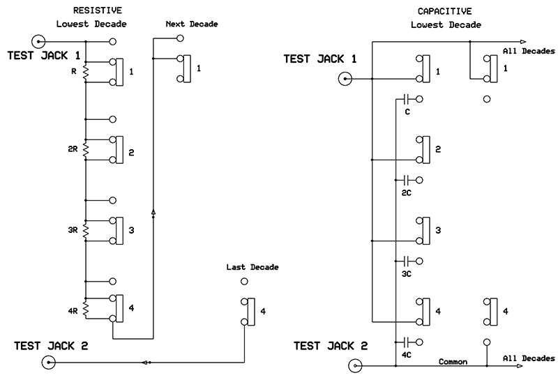
FIGURE 5. Slide switching using 1-2-3-4 add format.
The Capacitance Decade Box
Next up is the capacitor decade box. These will be more expensive to build. Again, starting with the digital type of switching, most advantages/disadvantages apply here as its resistive counterpart. For the digital style of switching, the BCD type is the preferred switching mode here — especially since all caps are connected in parallel to a common bus. This will use four base values of capacitance in a 1C, 2C, 4C, 8C arrangement.
It will need two caps in parallel for three of these values because base values 2, 4, and 8 are almost impossible to obtain, so — in reality — it will take seven caps per switch (i.e., 0.47 µF + 0.33 µF = 0.8 µF).
Obviously, these will occupy more space than the pinout board can handle, so they will partially hang off the pinout board and require a little more box depth than the companion resistor box did. Since these switches have a 50V limit, SMD capacitors would work nicely here if you can find the tight tolerance you desire at an affordable price.
The SMD parts will also allow for a smaller box. Refer to Figures 6 and 7 for the schematic diagram and an image of a completed switch using through-hole components.
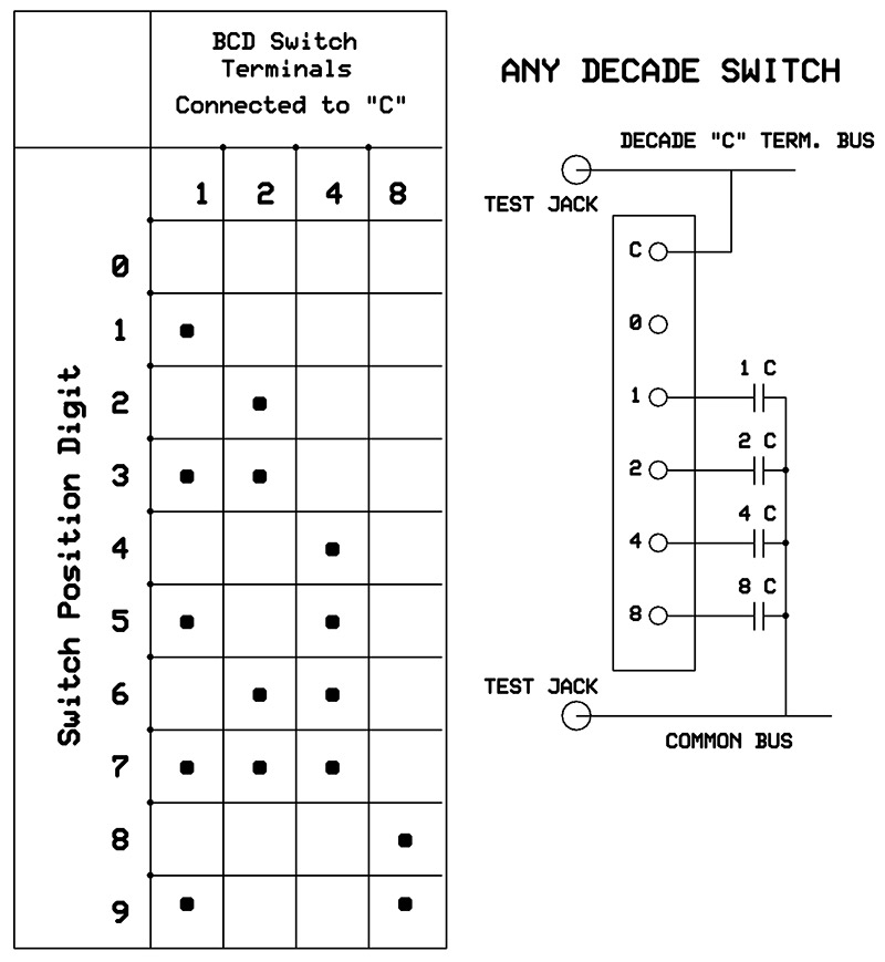
FIGURE 6. Capacitance box digital switch.
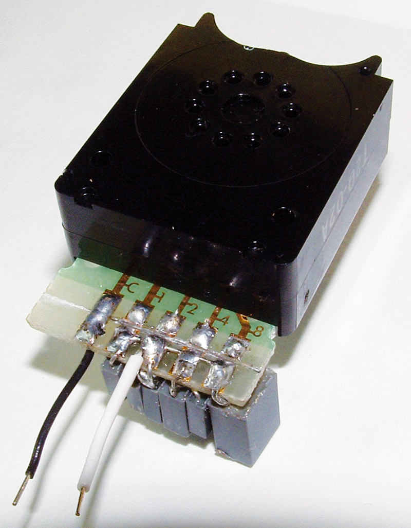
FIGURE 7.
As opposed to the series connected components in the resistor boxes, capacitor box components are all wired up in parallel to a common bus wire. The base value components are each connected to their corresponding pinout numbers (base value 1 - pin 1; base value 2 - pin 2, etc.). The C terminal is then tied in parallel to the other decade switch’s C terminals and to one of the test jack terminals.
The other leads of all capacitors are connected to the common bus and to the other test jack terminal. For this switch, I used 5%/100V metallized polyester capacitors, so a populated decade switch cost me $2.20 each. Although you can use as many active decades as desired, I only used four: one active but unpopulated decade, and two “dummy” decades to complete this box. The readout (shown in Figure 10) is 0.000040 microfarads.
The unpopulated leading digit is awaiting a decent price and size for these larger components. The last two digits (dummies) have been locked in place for ease of reading the total display in microfarads. Why are these two locked at “40?”
Since the parasitic capacitance of most capacitor decade boxes is around 30-50 pF, there is not much need for a 10s and 1s digit because they are so severely degraded. As long as these digits are present, they might as well be locked at 40 which is the exact total parasitic capacitance of this assembly. This way, they serve a more useful purpose.
The end result displayed is 0.xxxx40 µF, with ‘x’ identifying the active decades. In time, the leading digit will be populated for future use. As it stands now, the total cost including the box for this completed unit was $16.
The Capacitance Decade Box with Rotary Switching
Now for the “king of the hill” capacitive decade box: the rotary style of switching. This can get quite expensive since these switches can handle about any capacitor you want to wire up to them — high voltage and/or high value. A lot of decisions and web searching may have to be made here to reach a balance as to quality vs. cost. Depending on switch arrangement, there are only three choices here.
First, a single pole/11 position wafer switch with 10 base values (0-10) of capacitors for each decade. The switch is cheap, but the cost of capacitors would be out of sight! Next option would be a BCD type of switching using only four base values (1-2-4-8). A big savings here on capacitors, but the switch would require four poles and would need four separate decks to accomplish this. Less cost in terms of capacity, but the cost for the bare switch from major distributors will be astronomical ($60-$70) and very bulky.
An interesting side note here is that the relatively cheap decade boxes of the past used a special BCD arrangement that had only one wafer. It had a couple more terminal lugs and a special cut wiper plate so that manufacturing costs were little more than today’s simple and cheap single deck 11 position wafer switch. It’s sad to say these are now unobtainable, at least to the best of my knowledge.
I really gave this one a lot of thought and came up with a pretty good solution. I call it a “10 of 5” switch which utilizes two wafers in a DP/11T configuration and five base value caps to produce the whole decade of 10 values. Refer to Figures 8 and 9 for the schematic and populated switch. Again, 5%/100V metalized polyester film caps were used here. The common end of the caps was soldered to the switch’s metal binding bracket on the rear as shown.

FIGURE 8. Capacitance box 11 position rotary switch.

FIGURE 9.
These points were ultimately wired together and tied to the common test jack after installation to the front panel. When I placed an order for these caps, I ordered three of each value because their price was so low. To you newbies out there, you may want to do the same if a fantastic deal presents itself. Not only do you amortize the postage over more parts, but this is how you eventually build up your stock. After almost 40 years of over-ordering like this, I have built up a stockpile of components that almost anything I need is within arm’s reach. It will increase the pleasure of your hobby tenfold by doing this.
Before installing these caps, I got curious as to how accurate they really were and went about checking each one. More than nine out of 10 were within 2-3% of the stated value. That’s pretty close to the target value and adequately sufficient for subbing. The decade switch pictured cost $3.10 (each) and the caps averaged $2.20 per decade ($5.30 for a populated switch). Adding $10 for the box and knobs, a four decade box (100 pF to 1.0 µF) cost $31 total.
Of course, when using a switch like this that can handle just about anything you can attach to it, the ultimate goal would be 1% tolerance and several hundred volt ratings, and possibly one more decade of 1 µF steps. If one were to realize this, it would not come cheap, but with enough web searching and careful buying you could come close. For the highest value decade (1-10 µF), 10% tolerance would be sufficient and keep the cost down on these larger values. As the old engineering saying goes, “It’s not perfect, but close enough.”
Closing Notes
These sub boxes perform their best from DC to several MHz, so when used at higher frequencies, one has to take into consideration internal parasitic reactances that will have more effect as the frequency goes upward. So, basically, resistor box components are always wired in series; capacitor box components are always wired in parallel.
Resistor boxes are very inexpensive to build. Capacitor boxes can be relatively inexpensive to build or they can be very expensive depending on the number of decades used and the voltage/tolerance level desired. This covers a lot of levels of increasing quality. The choice is yours.
Whatever you decide, I would recommend you populate the decade switches first; lay them out as they would ultimately be assembled to the front panel and then purchase a box to fit. However, with a little forethought on the sizes of switches and components, you could possibly order the box from the same supplier thereby saving on postage. The resistor box shown in Figure 10 is 3-1/2” W x 5-1/4” L x 1-1/4” H (a little tight).
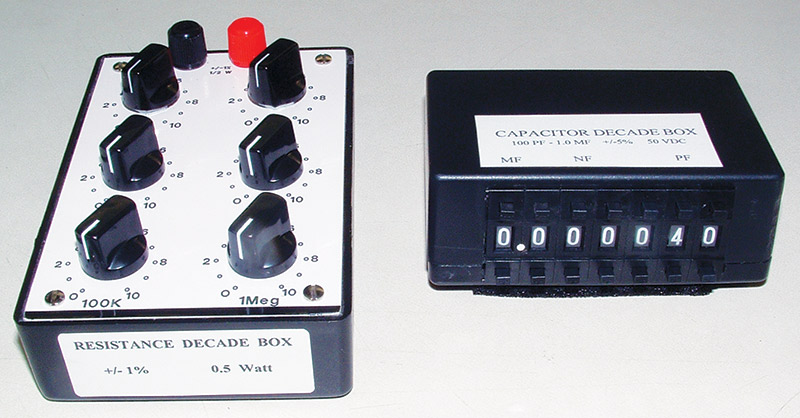
FIGURE 10.
The capacitor box in that same photo is 4” W x 2-1/2” L x 1-1/2” H (a little deep to allow for test jacks on the rear which is hidden from view in the image). Also, the white and black leads for decade switch connections are just to help clarify these points to their respective schematics. In practice, the decades would all be wired together with one color.
As much as I dislike suggesting secondary distributors, the cost of switches from major distributors is just too prohibitive. The resistive single pole/12 position switch I used was purchased from Tayda Electronics, along with most of the components and boxes. You can download their catalog and order online at www.taydaelectronics.com.
All the rest of the switches shown were purchased on eBay from China. There just seems to be an unending supply there from a multitude of sellers. Prices and sellers keep changing frequently, so rather than recommending one over the other, you’re better off just plugging into the eBay search box and go for the best deal. (Of course, you should check out what Nuts & Volts’ advertisers have to offer first!) The capacitive rotary switch is a two pole/11 position, and will have two wafer decks. The digital switches usually come in a bank of 10.
Two cautions here: Use straight decimals for resistors and BCD for capacitors; and check the specs for the height of the switch which should be about 1-1/4” high (most of these will be this height).
Although there is a lot of information on the Internet on sub boxes, my objective here was to consolidate all the information into one “arena” so you can weigh the styles and options available. I hope this will simplify your choices if you decide to DIY your own.
The parts for these boxes are quite inexpensive and easy to construct. Build a couple, use them, and enjoy them for years to come! NV
Downloads
What’s in the zip?
Express PCB files for all schematics