When a PIC can Replace a 555
Engineers Mini-Notebook 555 Circuits by Forrest M. Mimms, III ©1984. Also see www.forrestmims.org.
This installment will examine the more complex circuits from the “555 Timer IC Circuits” by Forrest Mims which are variations on audio oscillators. Some will use the PIC replacement from Part 1, while others will develop specific programs using a PIC to emulate a particular implementation of a 555.
Just as a quick review, the first article in this series described a general-purpose 555 replacement using a PIC microprocessor: the 12F1572. The second article reviewed the circuits and their PIC equivalents, which used the 555 basically as a mono-stable multivibrator. Part 3 discussed the less complex audio oscillator circuits.
References to the PIC replacement refer to version 1.4 of the program. This version makes three enhancements to the original: all astable modes (modes 4-6) use pin 4 as a gate input; mode 5 replaces the off-time function with period; and mode 6 is a metronome.
Many of the circuits in this article refer to a piezo element or buzzer. The units required for these circuits are usually of the internally driven type which are polarity sensitive and are labeled with a + sign for the positive terminal. Where I have modified component values in any circuits, I show the original values in parentheses. Also, those components marked with an asterisk (*) are additional components not in the original.
A note about the resistor values for selecting the Range and/or Mode for the PIC 555 replacement: The ratio of the resistors is what is important as long as the parallel combination is less than 10K. For instance, the schematics show 2.5K and 5.5K when selecting Range and/or Mode 5 (or Mode 2). You can use any resistor combination that has a ratio within 10% of 0.45 (2.5/5.5). Values of 2.7K and 5.6K, ratio = .48, will work just fine.
Mims Circuit 14
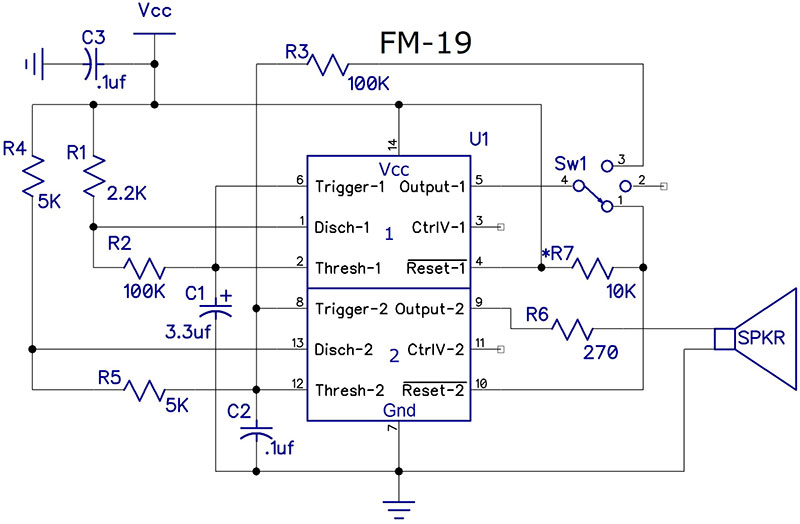
One of the applications of Circuit 14 (Schematic 1) shows the 555 being used as a metronome which uses the 2.2 µF capacitor and the piezo element. If you use a piezo element without an internal driver (as specified in the book), you will get a click for each beat. I prefer a tone which requires one with the internal driver.
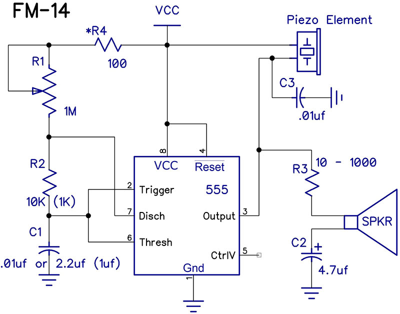
SCHEMATIC 1. 555 metronome or tone oscillator.
You may want to increase the value of R2 somewhat to make the on time longer. With the 1K resistor of the original schematic, I had a pulse width (output low) of about 850 µs. A 10K resistor yields a pulse width of about 15 ms and doesn’t change the frequency much while enabling the tone to be heard.
I added R4 just to ensure at least some resistance when the pot resistance is zero. I added C3 because without it, the piezo element (Digi-Key #668-1458-ND) emitted noise. Using a 2.2 µF capacitor for C1 gave me a better range for the metronome than the 1 µF specified in the book.
With the circuit as shown, the frequency ranged from about 0.5 Hz to 30 Hz. You may want to experiment with the values of C1, R1, R2, and R4 to give you a good tempo range and tone. Using the formula for the frequency of a 555 astable, the following values will give a beats per minute range of 8 to 120:
R1=1M, R2=10K, R4=50K, and C1=10 µF.
Using Mode 4 or 5 of the PIC 555 replacement will give you the same results as using a 555. However, during the Christmas holidays this past year, I found out that one of my grandsons started playing the trumpet. This sounded like a good excuse to develop an electronic metronome using the PIC 555 replacement.
Mode 6 has been added with the following modifications to the “standard” I/O of the PIC 555 replacement:
- Pin 5 controls the beats per measure.
- Pin 6 controls the tempo or beats per minute.
- Pin 7 changes to an output after getting the range, to drive a downbeat LED.
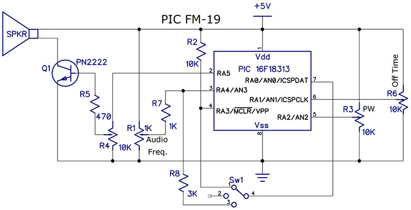
The normal tone frequency of the beats is 400 Hz, while the downbeat frequency is 800 Hz; refer to Schematic 2 for my implementation.
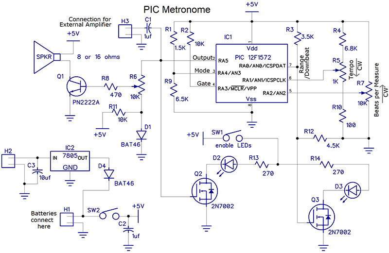
SCHEMATIC 2. PIC 555 metronome.
One LED is driven by the same signal as the speaker, while another is driven by the downbeat signal. Using the switch, you can enable or disable the LEDs. You can increase the value of R13 and R14 if you use high brightness LEDs. This will reduce the current drain and will be important if you run from batteries.
The beats per measure is determined by R7 and a look-up table. The basic value is obtained in the same way that the Mode and Range are determined — using the three most significant bits of the A/D reading. The software allows eight discrete values: 0–7. However, that value is then used as an index into a table to get the actual beats per measure. There are currently seven values implemented: 0, 2, 3, 4, 6, 8, and 12. The value of 0 is used to indicate no downbeat. The eighth value is also 12 so as not to leave it blank.
Picture 1 shows the output with four beats per measure. The bursts are about 100 ms. The bottom trace is the downbeat LED signal which surrounds the downbeat tone. You can see that the tempo is quite high since the period of the tones is 250 ms — equivalent to 4 Hz — so the tempo would be 240 beats per minute. I did this purposely to make getting the ‘scope picture easier.
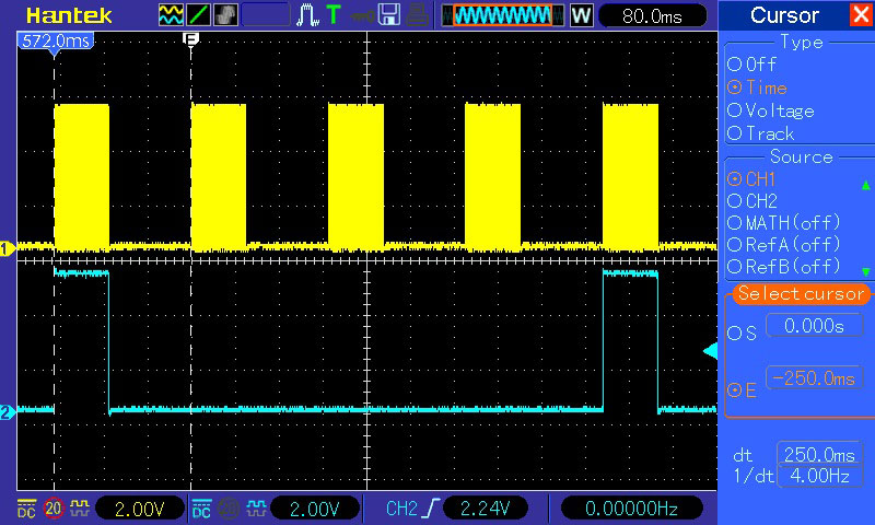
PICTURE 1. PIC 555 metronome waveforms.
With the resistors shown, the tempo range is about 25 to 540 beats per minute. R10 affects mostly the high-end tempo, so if you want to decrease the maximum tempo all you need to do is increase its value.
If you want to use a piezo element, you can connect it to the PIC output, but you should put a pot in series with it to control the volume. Since the output of the PIC is a tone, the piezo device should not be of the internally driven type. If you need more volume, you can use the transistor driver shown in the schematic.
A few comments about the circuit. Diode D1 in the speaker driver circuit adds a little bias to R6 to reduce the amount of pot rotation needed before you get any sound out of the speaker.
I mounted a holder for three AA batteries on the back of my unit, but I would not recommend prolonged use with batteries since the current drain can easily exceed 100 ma with a reasonable speaker volume.
Provision is made for an external power supply via H2. Any DC voltage between 7V and 35V will work with the regulator. However, voltages higher than about 15 may require a heatsink.
I mounted a standard DC power socket such that the batteries must be removed to connect external power. H3 is used to allow an audio jack to connect the output to an external amplifier.
The other application of Circuit 14 is that of an audio oscillator. The value of C1 should be .01 µF to increase the frequency to the audio range. The range of frequencies with the components shown in Schematic 1 is approximately 120 Hz to 7 kHz.
One of the issues of the 555 in this type of circuit is that as you vary the resistance of R1 to get different frequencies, you are only modifying the charge time (output high) of C1 while the discharge time (output low) remains constant. The audible effect of this is that as the frequency is lowered, the duty cycle is increased, and the sound produced has more harmonics.
Pictures 2-4 show this using FFT displays. Picture 2 shows 100 Hz at 50% duty cycle. Note that the amplitude of the 3rd and 5th harmonics are decreasing in about 10 dB steps, while the even harmonics are down about 30 dB. The higher odd harmonics continue the trend.
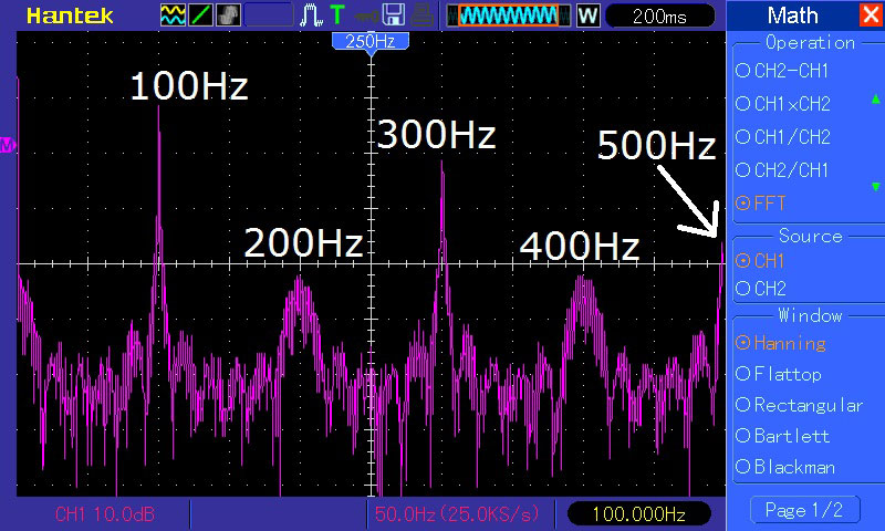
PICTURE 2. FFT of 100 Hz, 50% duty cycle square wave.
Picture 3 is 75% duty cycle, and shows both even and odd harmonics are high but are decreasing about 3 dB per harmonic.
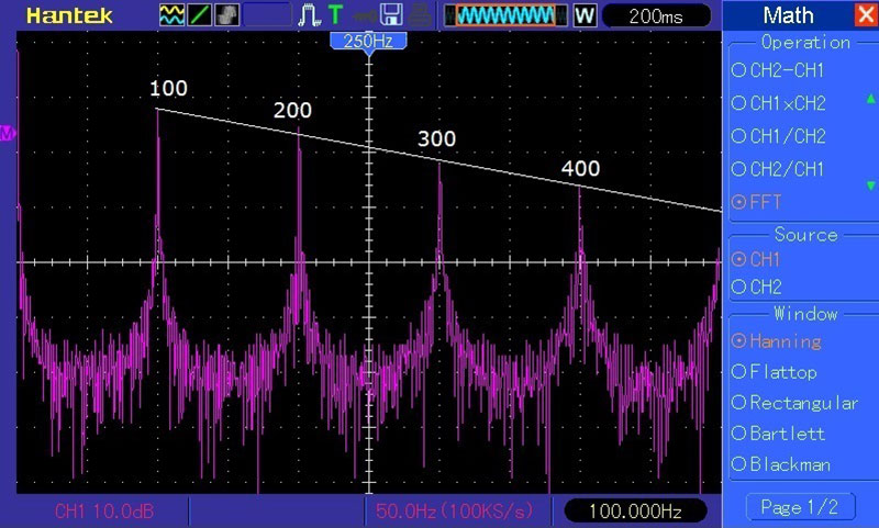
PICTURE 3. FFT of 100 Hz, 75% duty cycle square wave.
Picture 4 is 90% duty cycle and shows that all harmonics are very close to the same amplitude as the 100 Hz fundamental.
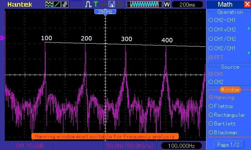
PICTURE 4. FFT of 100 Hz, 90% duty cycle square wave.
You can use one of the circuits (Schematic 3) from Part 3 for the PIC audio oscillator equivalent of Mims Circuit 14. Using Range 1 allows the frequency to be adjusted within a useful audio range. Keep in mind that with the PIC emulating a one-shot, the pulse width — or period — is the parameter being controlled. This means that a small change in control voltage at the high frequency end (lower voltages) will yield a large change in frequency.
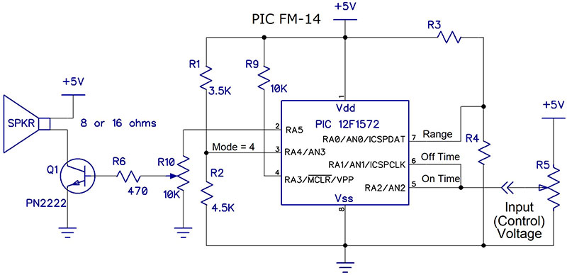
SCHEMATIC 3. PIC 555 voltage controlled audio oscillator.
The narrowest pulse width is about 30 µs, giving a period of about 60 µs (16.66 kHz), with a resolution of 10 µs. The next lower frequency is about 12 kHz, period = about 82 µs. Note that the period resolution is double the pulse width resolution.
Another solution for a PIC based audio oscillator is the NCO discussed in Part 3 of this series (and shown here in Schematic 5). Although the schematic is for a toy organ (discussed next), you can replace the resistor network on pin 5 with a simple divider or potentiometer.
Mims Circuit 15
Circuit 15 (Schematic 4) shows the 555 being utilized as a toy organ using different value capacitors to develop the different frequencies. With all switches open, the output will be high. As soon as one (or more) of the switches is closed, the 555 will start to oscillate.
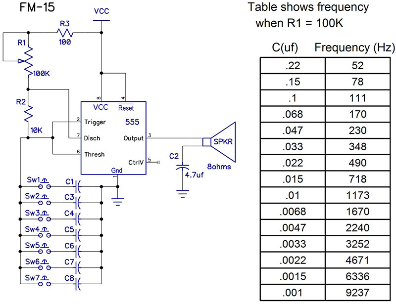
SCHEMATIC 4. 555 toy organ.
Schematic 5 shows an easy way to implement a toy organ using a PIC NCO with the program NCO_Toy_Organ.asm (available with the downloads). The purpose of the diodes is to enable the output by grounding the gate when the associated switch is closed. Range 0 for the NCO is the most appropriate for an audio application: 7.5 Hz to about 7.5 kHz. If you want a higher maximum frequency but still stay within the audio range, you can modify the program so that the A/D value is doubled. This will make the lowest frequency and step size about 15 Hz, and the highest frequency about 15 kHz.
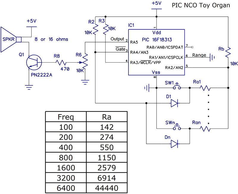
SCHEMATIC 5. PIC NCO toy organ.
If you want a little bit more complex solution with a step size of 9.4 Hz (closer to 10 Hz), you can multiply the A/D reading by 1.25 by dividing the reading by four (two right-shift operations) and then adding the result to the original value. Since the NCO has a linear frequency vs. voltage curve, it becomes easy to calculate the ratio of the two resistors required for any frequency: let Ra = lower resistor, Rb = upper resistor of the voltage divider, and Ra = n*Rb. The formula for the control voltage is:
Vcontrol = (Ra x Vcc) ⁄ (Ra + Rb) = n x Vcc/(n + 1)
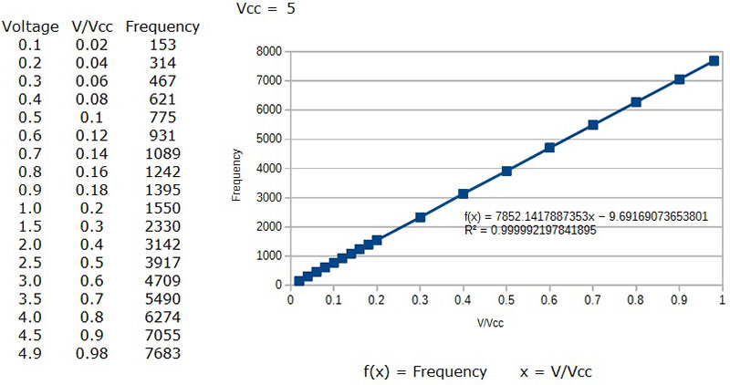
GRAPH 1. PIC NCO frequency vs. control voltage.
The formula for the frequency can be obtained from Graph 1 and simplified a little:
Freq = (7852 x V/Vcc) — 9.69
By manipulating these two equations, the value for n as a function of frequency can be derived as:
n = (Freq + 9.69) ⁄ (7852 — 9.69 — Freq)
Notice that n is independent of Vcc, and that the maximum frequency is about 7,842 Hz. For instance, if 200 Hz is wanted, then n = .0274. Letting Rb = 10K, then Ra = 274 ohms. The spreadsheet NCO Toy Organ.ods in the article downloads uses the above formula to calculate the Ra value for several frequencies using 10K for Rb. The schematic shows the values as calculated by the spreadsheet for seven frequencies.
The PIC replacement (mode 4 and range 1) can be used for this application as well. Using the same approach as with the NCO, the formula for n can be derived as:
n = 1 ⁄ ((.02048 x Freq) — 1)
If Rb is fixed at 10K, the formula for Ra is:
Ra = 104 ⁄ ((.02048 x Freq) — 1)
Note that with this circuit, the lower resistor values give shorter periods thus higher frequencies — just the opposite of the NCO. There will be three differences using the 555 replacement as compared to the NCO:
- The calculations for the resistor values since the control voltage is controlling the period.
- The high frequency resolution is not very good. See the discussion about resolution in the PIC Mims Circuit 11 section.
- The gate circuit needs to have an inverter since the gate is high true. See Schematic 5a.
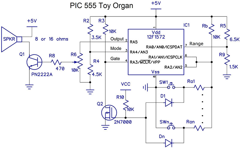
SCHEMATIC 5A. PIC 555 toy organ.
Mims Circuit 17
Circuit 17 (Schematic 6) is a 556 connected as a chirp generator. Section 1 of the 556 is an astable multivibrator. It has a frequency range from under 1 Hz to about 60 Hz.
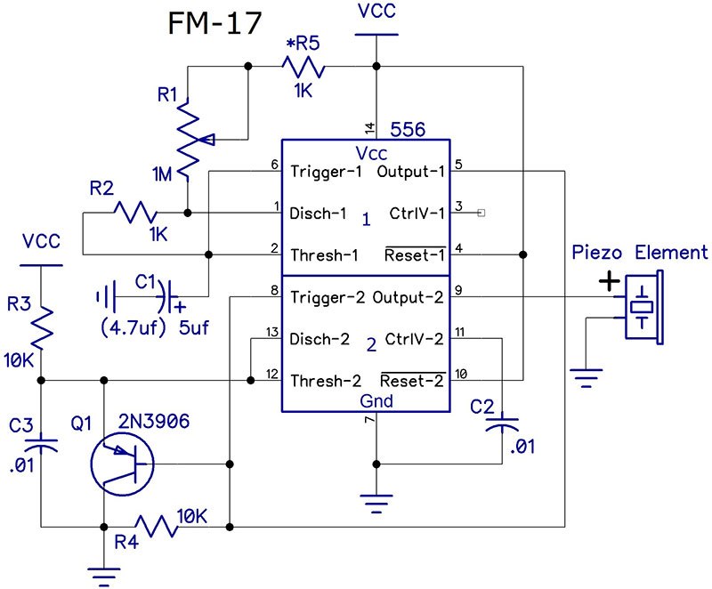
SCHEMATIC 6. 556 chirp generator.
Based on the formula from a 555 spec sheet, using the R2 and C1 values shown in the schematic, the width of the pulse low time for the astable section is PW = 0.693*R2*C1 = 3.46 ms. I measured 3.38 ms which is quite close to the calculated value.
The second section of the 556 is wired as a mono-stable multivibrator and should have a quite short output pulse. The formula for the pulse width of the monostable section is PW = 1.1*R3*C3 = 110 µs. When the trigger signal goes low, the 555 output immediately switches high and the capacitor starts to charge. However, since the trigger is low for longer than the calculated pulse width, the capacitor does not charge completely. It only charges to about 0.7V due to Q1 being on.
Picture 5 shows the results with and without Q1. A is the triggering pulse from the astable; the actual triggering edge is off the screen to the left. B is the voltage across C3 when the transistor is in place.
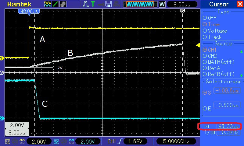
PICTURE 5. 556 chirp generator capacitor charge and discharge.
You can see that the capacitor voltage is clamped at about 0.7V until the triggering signal goes high, at which time the capacitor is allowed to complete its charging. The capacitor charges only to the threshold voltage, which then enables the internal discharge circuit.
C shows the capacitor voltage with Q1 removed. It charges to the power supply voltage since the discharge circuit is disabled, as long as the trigger is low. The slope of the discharge is due to the finite amount of current the discharge circuit can pull from the capacitor. Using the formula cv=it, the current calculates to about 14 ma: .01 µF * 5V/3.55 µs. The only difference between having the transistor in the circuit vs. out of the circuit is that with the transistor, the output pulse is about 97 µs wider that without it. This is somewhat shorter than the 110 µs calculated previously due to the capacitor starting from .7V rather than 0.
Since the output pulse width on pin 9 is basically the same as the trigger pulse from pin 5 — except that it’s inverted — the same effect can be achieved with a 555 using the same timing components as Section 1 of the 556 by connecting the piezo element between the output and Vcc. If you use the circuit as a warning device, you can use the Reset input to enable and disable the oscillator.
To use the PIC replacement, you can work the circuit shown in Schematic 7. The schematic shows Range 3 (1 ms to 1 sec) and mode 5 which are probably the best for this application. You can adjust R6 to give you the desired tone/chirp duration, and R5 to set the repetition rate/period. If you use mode 4, then R5 would adjust the time between chirps.
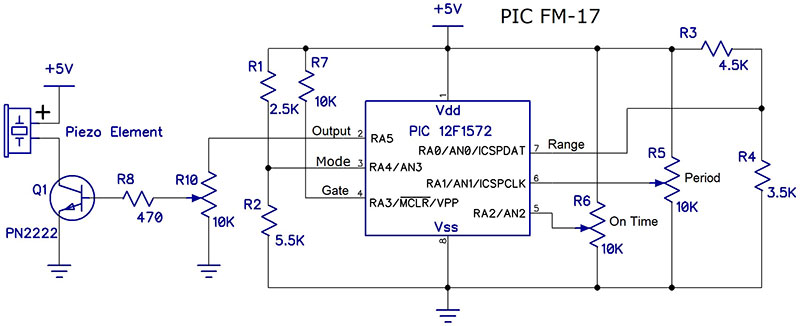
SCHEMATIC 7. PIC 555 chirp generator.
Mims Circuit 18
Circuit 18 in the Mims book (Schematic 8) — called a Stepped Tone Generator — took me a while to understand what was happening.
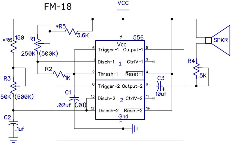
SCHEMATIC 8. 556 stepped tone generator.
As it turns out, that although the graph is correct, the text is incorrect — the frequency rises and the step size (ΔF) increases as R3 is reduced.
To duplicate Mr. Mims results, I used a 50K pot for R3 to get better resolution. I set R3 so that the pulse width on pin 9 was about 200 µs and adjusted R1 such that the input and output frequencies were the same at 2 kHz.
I then rotated R3 through each of the step frequency changes and measured its resistance.
The results are shown in Graph 2 which closely matches Mr. Mims results. As you can see, the output frequencies are sub multiples of the 2,000 Hz fundamental.
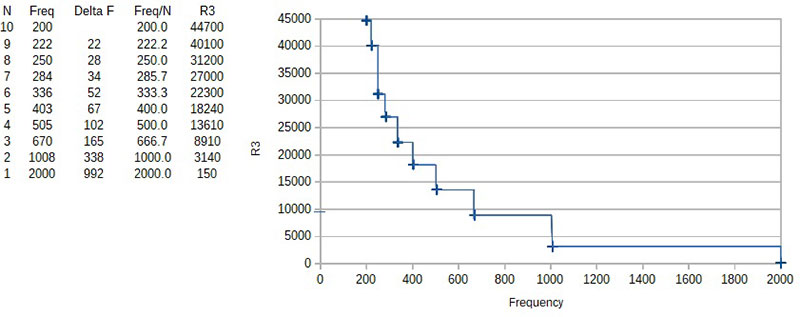
GRAPH 2. 556 stepped tone generator: frequency vs. R3.
Section 1 of the 556 is wired as an astable multivibrator with a frequency range of about 282 Hz to 12.8 kHz. Section 2 is a monostable triggered by Section 1, with an output pulse width range of about 16 µs to 5 ms.
The operation of Section 2 is that of a frequency divider (see Part 2 of this series for a detailed explanation).
For any single setting of R1 (period), as R3 is changed, the output frequency will be constant until a pulse width threshold is reached (N*period), at which time its output frequency will jump to its next value.
Changing the period of Section 1 will change the output frequencies of Section 2 at which it jumps. You should also note that even though the monostable frequency does not change until the threshold is reached, the tone sound will change because the duty cycle of the pulse is changing.
Using two PIC 555 replacement ICs will operate exactly in the same way if you set one to mode 4 or 5 (astable) and the other to mode 0 (monostable). Also, the program of Mims Circuit 21 (discussed later in this article) will yield similar results if all you want is an output that steps among several frequencies.
Program NCO_SteppedTone Gen.asm in the downloads emulates this circuit by implementing essentially two 555s.
One uses the NCO of a 16F18313 to emulate a 555 astable mode; the second uses a timer to enable emulation of a 555 in its monostable mode.
Schematic 9 shows the circuit which duplicates the stepped tone generator where R1 changes the astable frequency and R3 changes the monostable pulse width.

SCHEMATIC 9. PIC stepped tone generator.
Mims Circuit 19
Circuit 19 is titled as a Three-State Tone Generator; refer to Schematic 10. Both sections of the 556 are wired as astable multivibrators. The components of Section 1 cause it to operate at a frequency of about 2.1 Hz with close to a 50% duty cycle, while those of Section 2 cause it to operate at about 960 Hz with a 66% duty cycle.
SCHEMATIC 10. 556 three-state tone generator.
With the switch in position 1, the output of Section 1 is used as a gate for Section 2. Section 2 will output its 960 Hz signal only while the output of Section 1 is high; about 230 ms. With the switch in its center position, the output of Section 2 will be a continuous signal. When in position 3, the output of Section 1 will affect the charge and discharge of C2, so that Section 2 will output two different frequencies. The difference between the frequencies is affected by the value of R3. The smaller the value, the larger the effect.
You can do the same thing using two of the PIC 555 replacements. However, program NCO_3_StateToneGen.asm (also with the article downloads) uses a single PIC16F18313 to emulate the same circuit with somewhat more flexibility; see Schematic 11.
SCHEMATIC 11. PIC three-state tone generator.
Pins 5, 6, and 7 are an astable with separate on-time and off-time controls, and a frequency range of about 0.1 Hz to 100 Hz. To get this low frequency range, I used one of the timers to generate a 200 Hz interrupt. In the Interrupt Service Routine (ISR), I count the number of interrupts in order to determine when to turn the pulse on and off. Initially, I wanted to use one of the PWM systems but was unable to get the low frequencies I wanted and still maintain a higher CPU clock frequency.
Pins 1, 2, and 3 are an astable which uses the NCO system to generate a square wave with a frequency range of about 7.5 Hz to 8 kHz. The source code in the downloads is well documented and should be easy to modify if you have a need to change any of the operating characteristics. The switch and its three positions duplicate the operation of the 556 implementation.
Mims Circuit 21
Circuit 21 (Schematic 12) is a sound effects generator. Both 555s are wired as astable multivibrators. However, the second 555 is also used as a VCO. IC1 has a frequency ranging from about 2.4 Hz to 10 Hz, and its output drives an R-C circuit which is used to modify the control voltage of IC2. The output of IC2 is a tone which decreases in frequency as C2 is charging, and then increases as C2 discharges.
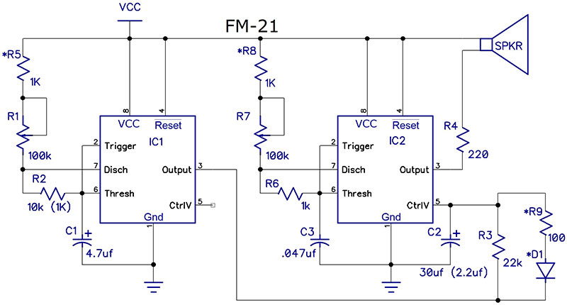
SCHEMATIC 12. 555 sound effects generator.
IC1 controls how far C2 charges and discharges by varying the charge time — IC1 pin 3 is high. The discharge time is constant. IC2 develops the basic tone output. Without the VCO circuit (components connected to IC2 pin 5), the frequency varies from about 400 Hz to 12 kHz.
I have made several modifications to the circuit which give it more options for the sounds it produces. The larger value of C2 causes the frequency change to be slower. Increasing R2 allows C2 more time to discharge, and the addition of R9 and D1 allows C2 to discharge more fully, yielding a wider range of frequency variation since there will be a substantially lower minimum voltage on C2. Program NCO_SoundEffects.asm uses the NCO peripheral of the 16F18313 to generate a wide range of sound effects. Schematic 13 shows the controls which allow you to create the various sound effects.
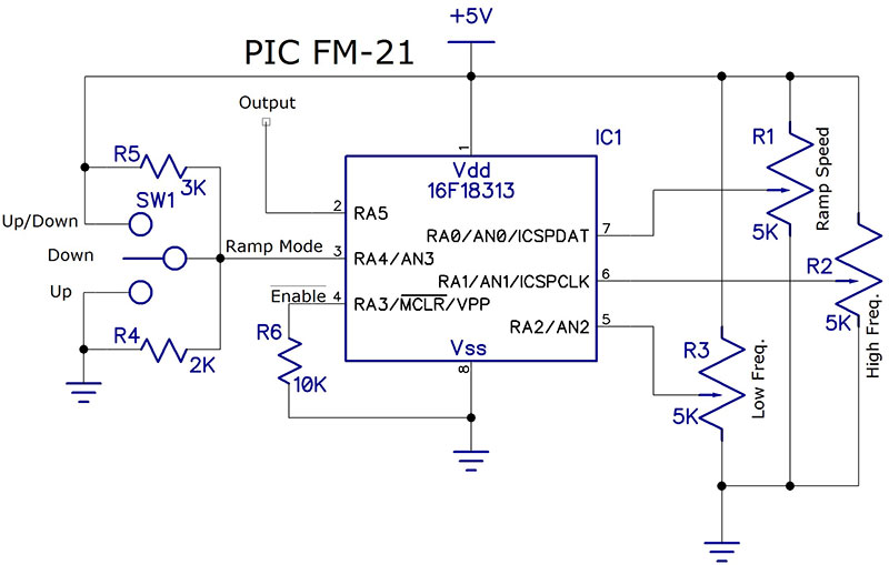
SCHEMATIC 13. PIC sound effects generator.
The operation — except for the speed control — is quite simple: The program ramps between two frequencies in discrete steps. SW1 allows you to choose among ramp up, ramp down, or a bi-directional ramp. R3 sets the lower frequency limit with 15 Hz resolution up to about 3.8 kHz. R2 sets the high frequency, but it’s an offset from the low frequency. For R2 and R3 (the frequency controls), the program uses only the upper eight bits of the A/D reading. For R1, ramp speed, only the upper six bits are used. SW1 is also an analog input with only the upper two bits of the reading being used.
The ramp speed, R1, is a bit more complex. There are two parameters which change with the R1 setting: the step size in Hz, using bits 9-7 of the A/D reading; and the step duration, using bits 6-4.
Both the step size and duration bits are used as indices into tables of eight values each, so they can easily be changed if you want. With the R1 tap at ground, the step size is 15 Hz and the duration per step is 100 ms. Rotating the pot a little changes the duration to 50 ms while keeping the step size the same.
Basically, for each step size, the program will change the duration from its maximum of 100 ms to its minimum of 1 ms. After reaching 15 Hz and 1 ms, the next setting will be a step size of 30 Hz with a duration of 100 ms. The maximum step size is currently a value of 25*15 Hz = 375 Hz, so the maximum speed is attained with the R1 tap at 5V and yields a step size of 375 Hz with a step duration of 1 ms.
All the inputs can be varied during program execution. However, they are read and applied only at the end of each ramp cycle. Also, although the pots are shown as 5K, they can be any value up to 10K which is the specified maximum source resistance for the PIC A/D.
Since I used the 16F18313 in a number of these sample circuits, I decided to migrate the PIC 555 replacement from Part 1 of this series to this processor. You can find the code (PIC_555-16F.asm) with the downloads.
I have recently designed a breadboard for the PIC 555 replacement using the 12F1572 or 16F18313.
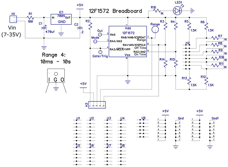
Schematic of breadboard.
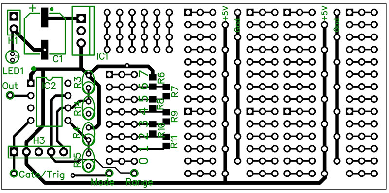
Top view of PIC 555 replacement breadboard.
The schematic and board layout can be seen in the file Breadboard.jpg in the downloads. The board has a 7805 regulator and a sizable area for breadboarding. It’s a mix of thru-hole and SMD parts, and has a programming header compatible with a PICKit-3. NV
(If you want a single board, you can email me at [email protected]. If you want to get three boards, you can order them from OshPark at oshpark.com/profiles/K3PTO.)
Resources
All schematics are drawn using DipTrace
www.diptrace.com
All parts purchased are from Digi-Key
www.digikey.com
My website
www.qsl.net/k3pto
Circuit Boards
https://oshpark.com/profiles/K3PTO
Downloads
What’s in the zip?
Schematic Files
Source Code
Graphs