What if you had multiple loop( ) sections in your Arduino sketch, all running at the same time? With an RTOS, this and more is possible.
What is an RTOS?
An RTOS (Real-Time Operating System) is a software component that lets you rapidly switch between different running sections of your code. Think of it as having several loop() functions in an Arduino sketch where they all run at the same time.
Everyone has experienced a multi-tasking operating system. On your smartphone or PC, you can be playing a game while you get an incoming call or text message. At the same time, you might be downloading a software update. All these tasks appear to be running at the same time but, in fact, there is only one CPU that is switching back and forth rapidly to give the illusion of multi-tasking.
There is one important thing about these operating systems running on your phone or PC in that they are not “real time” operating systems. There’s no way to predict when the text application will alert you after you receive a text or that the game you’re playing will redraw the screen. In this environment, it doesn’t matter much. You might see a single app slow down on your smartphone from time to time as other running tasks hog the processor’s power.
When it comes to your sketch though, you need things to happen in real time. For example, your sketch may be blinking an LED at a specific interval that indicates some sort of status, and you wouldn’t want it to blink erratically as other tasks are getting executed. If you have used a Raspberry Pi, you may have noticed how difficult it is to get an LED to blink consistently. This is a shortfall of using a non-real time OS. The magic of an RTOS is that your LED will blink exactly at the time interval you programmed, even though it’s running other tasks at the same time.
Getting Started
There are many RTOS’s available. The one we’ll be using is called FreeRTOS. It is open-source software that is free and doesn’t require a license to use it. It has already been “ported” (see sidebar) to the Arduino’s Atmel processor which makes it very easy to integrate into your sketches. It’s also part of the Arduino libraries, so it’s very easy to install.
To install FreeRTOS, open the Arduino IDE (integrated development environment). From the TOOLS menu, select the “Manage Libraries...” item. You can scroll through the list or type “FreeRTOS” into the search bar. You’ll see the window shown in Figure 1. Select the item “FreeRTOS by Richard Barry” and select the latest version. Click Install. After a few moments, the installation will be complete.
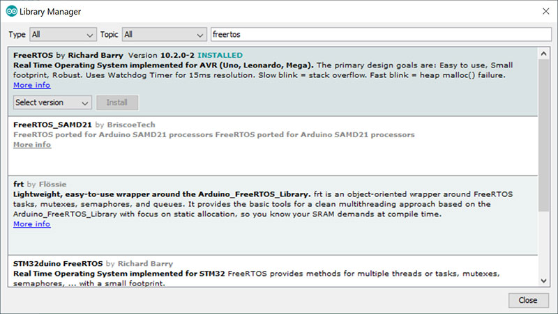
FIGURE 1. Installing the FreeRTOS library.
The first thing we need to do is create a task. A task is a thread or a function that runs independently of your other code. You create tasks in the setup() function of your sketch. You create a task by calling the xTaskCreate() function which takes several parameters:
xTaskCreate (
MyTask, // task function name
(const portCHAR *)”task1”, // human readable name
128, // stack size
NULL, // creation parameters
1, // Priority
NULL // returned task handle
);
MyTask – This is the name of a function in your sketch that holds the task code. You probably want to use a name that describes the function like “blinkLED” or “readSensor.” You then add a new function into your sketch that looks like this:
MyTask(void *)
{
// code goes here
}
const portCHAR *) “task1” – This is a name for the task. It’s not used at all by the RTOS. You can’t use NULL here. It must be a string of characters less than eight.
128 – This is the number of bytes to allocate for the stack. If you’re not familiar with a CPU stack, it’s a portion of memory set aside to save return addresses and local function variables when you call a function. If you call a function that calls another function, that then calls another function, etc., you’ll need more memory for the stack.
Here, we allocate 128 bytes, which is adequate for most sketches. If the stack size is too low in any of your tasks, the RTOS will blink the LED on the Arduino at four second intervals and stop your program.
NULL – This is a pointer to any predefined data or structure (defined by you) that you would like to pass to the task function when it’s created. To keep things simple, we’re not using this feature so it’s set to NULL.
1 – This parameter sets the task’s priority. It can be from 0 (lowest priority) to 2 (highest priority). When you have multiple tasks, you can alter the order and priority in which tasks run. This is an advanced feature. For now, set all your tasks to the same priority.
NULL – This is a pointer to a place to store the newly created task handle. We don’t need this for a simple sketch. Many RTOS functions will require the task handle when using more advanced API calls.
Once the setup() function ends, your tasks are created and they start to run. Figure 2 shows the process.
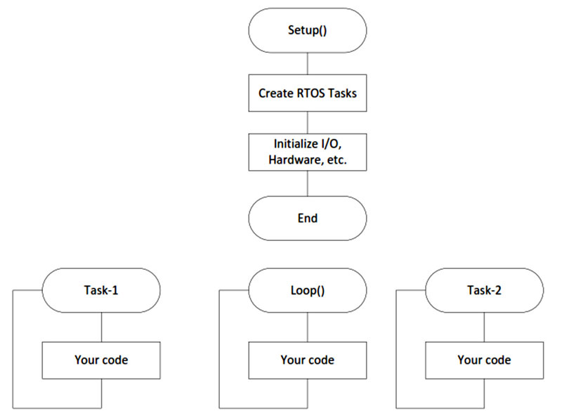
FIGURE 2. Flowchart of FreeRTOS tasks.
Think of Loop(), Task-1, and Task-2 all running at the same time. You can put whatever code you want in each. For example, Task-1 could be displaying characters on an LCD display, while Loop() is blinking an LED, while Task-2 is reading a temperature sensor.
First Sketch Using RTOS
Here’s a simple first sketch using FreeRTOS. We’re going to be blinking the built-in LED on the Arduino board while at the same time sending a string of text to the serial monitor. We’ll be creating two tasks, and just for fun, we won’t have any code in the loop() function. You can type in this sketch in the Arduino IDE or download it as RTOS_1.ino as part of the article.
1. // RTOS_1 1st Example of using FreeRTOS
2. // by Joe Jaworski
3. #include <Arduino_FreeRTOS.h>
4. const uint8_t LEDPin = 13; // Built-in LED I/O Pin
5. #define rtDelay(v) {vTaskDelay(v/15);} // delay in mS
6. // ***************
7. // setup() function
8. //
9. void setup()
10. {
11. // Setup our LED Blinky Task
12. xTaskCreate
13. (
TaskBlink, // function name
(const portCHAR *)”blink”, // task name
128, // stack size
NULL, // No creation parms
2, // Priority
NULL // returned task handle
14. );
15. // Setup our Serial Comm Task
16. xTaskCreate
17. (
TaskComm, // function name
(const portCHAR *)”comm”, // task name
128, // stack size
NULL, // No creation parms
2, // Priority
NULL // returned task handle
18. );
19. } // End Setup
20. // *****************
21. // loop() function
22. //
23. void loop()
24. {
25. /* Nothing to do here! */
26. } // End loop()
27. // **********************
28. // TaskBlink() function
29. //
30. void TaskBlink(void*)
31. {
32. pinMode(LEDPin, OUTPUT); // Set LED pin to OUTPUT
33. for(;;)
34. {
rtDelay(500);
digitalWrite(LEDPin, HIGH); // Turn on Led
rtDelay(500);
digitalWrite(LEDPin, LOW); // Turn off Led
35. }
36. } // End TaskBlink
37. // **********************
38. // TaskComm() function
39. //
40. void TaskComm(void*)
41. {
Serial.begin(9600); // Open Serial Monitor
42. for(;;)
43. {
Serial.println(“The LED is blinking now”);
rtDelay(500);
44. }
45. } // End TaskComm
Let’s go through this sketch line by line.
Line 3 has an #include <Arduino_FreeRTOS.h> which must be included in every sketch using FreeRTOS.
Line 4 defines a constant which is the I/O pin number of the built-in LED. Note that we’re using the C99 style declaration of uint8_t which is an unsigned eight-bit value, same as a byte. It would be good to learn and use these declarations in your sketches because it becomes easy to use your code on another CPU. It also shows the size of the variable (in this case, eight bits) which will help prevent coding errors.
On an eight-bit processor like the Atmel, your sketches will run much faster if you use uint8_t instead of int providing, of course, your data will fit into eight bits.
Porting an RTOS
An RTOS needs to be “ported” to a particular microprocessor. This is a daunting task that requires intimate knowledge of the microprocessor. Porting requires writing code (usually in assembly language) that integrates with the higher level functions or API of the RTOS. In this way, the functions remain the same no matter what processor is used.
The Atmel port uses interrupts and preserves most all of the Arduino’s functions and libraries without interference. This port uses the AVR watchdog timer for task switching interrupts. This means if your sketch is also using the watchdog timer, it will not work properly. All other interrupts should be fine to use. Many sketches that use FreeRTOS usually don’t need to use interrupts anymore as you can replace ISRs with tasks.
Line 5 is a bit confusing. It defines a macro called rtDelay(v), where v specifies the number of milliseconds to delay (see “Why have a special delay function?”). You should use this instead of the Arduino delay() function within tasks.
Why have a special delay function?
The job of an RTOS is to switch back and forth so that all your tasks appear to be running at the same time. The default run time of any given task (assuming equal priority) is 15 ms. This is called the tick count. Each task gets a “time slice” of 15 ms before it’s interrupted by the next task.
Just like most sketches, most tasks need to introduce delays in their code. Using a special form of delay tells the RTOS that “my task has nothing else to do for the next x milliseconds, so go run other tasks.” This makes the RTOS aware of the differences between your code and the dummy loops that make up delays. The RTOS becomes faster and more efficient.
There is one caveat to be aware of. Task switching occurs at a 15 ms rate, so the smallest delay is 15 ms, and all other delays are truncated to the nearest 15 ms increment. So, if you specify rtDelay(100), the delay will actually be 100 / 15 or 90 ms. If you need precise delays in a task, you could use the delay() function to make up the difference.
Lines 9-19 are the setup() function. Here, we create two RTOS tasks: one to blink the LED and the other to write text to the serial monitor.
Lines 23–26 are the loop() function. In this sketch, it’s empty! All the work is being done in tasks. However, you certainly could put whatever code you needed here without any restrictions.
Lines 30-36 are the TaskBlink() function. We set the I/O pin connected to the LED to an output, then blink the LED every 500 ms. Notice that we don’t call the delay() function and instead call the rtDelay()macro. This informs the RTOS that we need to be idle during the specified time. It’s best not to use the Arduino delay() function in a task; use rtDelay() instead.
Notice that the TaskBlink() function is wrapped in a never-ending loop via the for(;;) statement. This is very important! Tasks never return (where would they return to?) and will crash if you don’t use an infinite loop around the repeating code.
Lines 40-46 are the TaskComm() function. Here, we initialize the serial port to 9600 baud, then have an infinite loop that displays a line of text every 500 ms as shown in Figure 3.
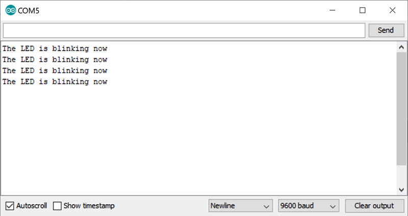
FIGURE 3. RTOS_1 sketch serial monitor output.
I recommend that you download or enter the code and run it on either an Arduino Uno or Nano. It’s quite remarkable to see this sketch in action and still have an empty loop() function, ready to do anything you need.
Exchanging Data Between Tasks
Our second example will modify this sketch so that the serial monitor will accept commands to set the LED to full on, full off, or blink. We’ll use a global variable that holds the state of the LED accessed by both tasks.
Using a global variable requires special attention in an RTOS. The problem is we don’t know exactly when the TaskComm() function or the TaskBlink() function is running at any given time. (It’s switching back and forth about 66 times a second.) With both functions having access to the same global variable, one function may be reading/writing to it while another function is doing the same, resulting in corrupt data. This is not unlike the problem faced when modifying global variables within an interrupt. We must somehow tell a task not to use the global variable until another task is done changing it.
The mechanism to do this is called a semaphore. It’s a way to alert all tasks that it must wait for the semaphore to be available before it can proceed. A semaphore is just a signal to the RTOS. It doesn’t do anything by itself. Your code defines what a semaphore does.
Semaphores have give and take functions. When you need to prevent other tasks from accessing a shared variable, you “take” the semaphore, which blocks all other tasks from using the variable until you’re done. When you’re finished, you “give” the semaphore back, which frees others to use it. Between the give and take functions is where you put your code. You can use a semaphore to protect global variables, sensors, hardware, or anything else that is accessed by more than one task.
With semaphores in hand, we’ll now modify the first example so that both tasks can use the global variable. At the top of the file, we add:
#include <semphr.h>
enum uint_8 {
LED_OFF, // LED ON
LED_ON, // LED Off
LED_Blink // Blinking LED
};
volatile SemaphoreHandle_t SemaStatus; // LED status semaphore
volatile uint8_t g_LEDStatus = LED_Blink; // Current LED status
The #include <semphr.h> specifies the header file that allows us to link with the semaphore library. Below that, we create the three states of the LED using the C enum keyword. We define a variable to hold the semaphore handle, followed by the global variable g_LEDStatus which is initialized to the LED blink state. Notice that both these statements use the volatile keyword. This prevents the compiler from optimizing out the variable, as it does not know that the variable will be modified within the RTOS task (which, in essence, is an interrupt).
The only change in the setup() function is to create the semaphore with the xSemaphoreCreateBinary() function and store its handle in the SemaStatus variable:
SemaStatus = xSemaphoreCreateBinary(); // Create semaphore
xSemaphoreGive(SemaStatus); // must GIVE after creation
We’re creating a “binary semaphore” which can either be given or taken. There are also “counting semaphores” which is a more advanced feature and not discussed here.
Within the infinite loop of the TaskBlink() function, we add a few lines to manage the semaphore and get the global variable:
xSemaphoreTake(SemaStatus, portMAX_DELAY);
Status = g_LEDStatus; // get a copy
xSemaphoreGive(SemaStatus);
Notice that we “take” it, then make a copy of the g_LEDStatus global variable, then immediately release it with the xSemaphoreGive(). It’s a good idea not to hold on to a semaphore for long periods of time, as you force other tasks to stop executing, waiting for you to release it. Same philosophies as using interrupt routines. You don’t want to have a lot of code in it and want to return it as soon as possible.
The parameter portMAX_DELAY is passed to the xSemaphoreTake() function. This tells the RTOS to wait forever until the semaphore is available. You can also specify how long you want to wait before giving up. In most cases though, your code probably needs the semaphore data before it can proceed anyway, so using portMAX_DELAY is very common.
The rest of the source in TaskBlink() uses a switch() statement to determine how to set the state of the LED.
Changes in the TaskComm() function are mostly to create an interactive environment so the user can enter data in the displayed menu as shown in Figure 4. We get the new status for the LED, then “take” the semaphore, write the new value to LEDStatus, then “give” the semaphore.
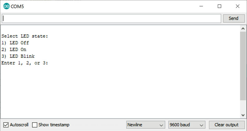
FIGURE 4. RTOS-2 sketch serial monitor menu.
If you’re a seasoned Arduino sketch writer, you’re probably thinking you could figure out how to do all this within the loop() function. Yes, you probably can, but dividing your code up into separate tasks makes your code very readable so you can easily make changes (especially six months from now when you forgot what you did).
As your code gets more complicated (especially where you have to have delays but need to do other things in the meantime), nothing beats an RTOS to manage the situation.
I urge you to visit https://www.freertos.org to learn more about this amazing software library and all it can do. NV
For a complete overview of FreeRTOS, go to www.freertos.org.
The detailed FreeRTOS API Reference can be found at www.freertos.org/a00106.html.
Downloads
What’s In The Zip?
Sketches