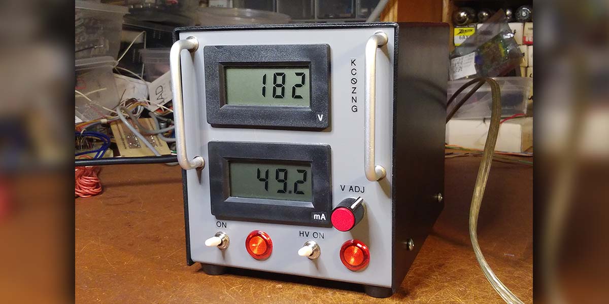
For those who experiment and build with vacuum tubes, an adjustable, regulated, benchtop high voltage power supply is essential. Many circuits for such units have been described that themselves use tubes. It’s nice to be consistent, but we can save some bench space and a few watts by using semiconductors in such a unit. This example is built around the LR8N3: a three-terminal high voltage regulator. It includes 6.3 VAC output for the tube’s filaments and digital metering. Figure 1 shows the supply.
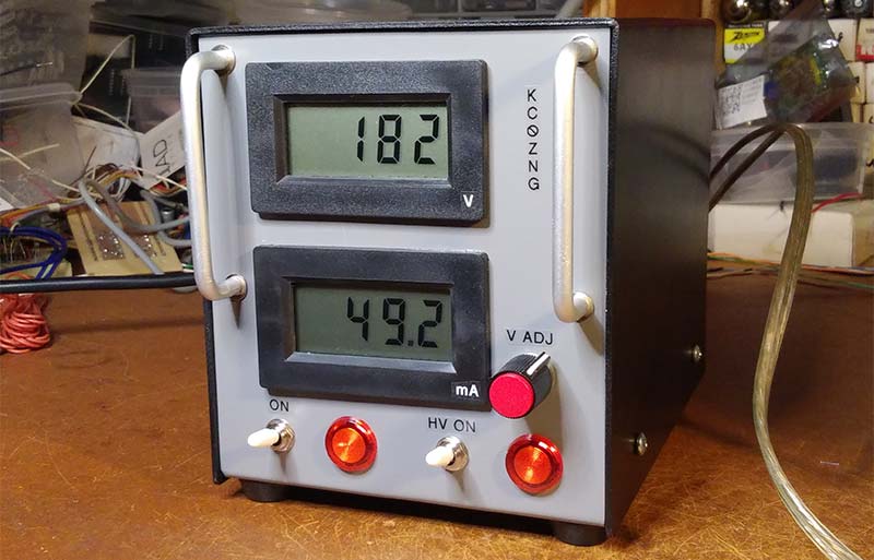
FIGURE 1. A semiconductor-based adjustable, regulated, high voltage power supply.
The Regulator
Like the familiar LM317, the LR8N3 is an adjustable positive three-terminal regulator. The big difference is that the LR8 is a high voltage regulator: Its input can be as high as 450V. Its output voltage is set by a voltage divider across its output as with lower voltage regulators; its maximum output is 12V less than its input.
Its maximum current is 20 mA, so any substantial supply requires a pass transistor; here, a TIP50. The LR8 is available in a TO-92 package and typically costs about sixty cents in small quantities. Figure 2 shows the regulator circuit.

FIGURE 2. High voltage regulator circuit using the LR8N3 three-terminal regulator.
The Power Supply
The supply is built around a salvaged transformer that is typical of power transformers for tube circuits. It has a center-tapped high voltage secondary — 480V at 55 mA — and two low voltage secondaries: 5V at 2A for the filament of a rectifier like a 5Y3; and 6.3V at 2A for other tubes.
Two diodes form a full-wave rectifier for the high voltage. Their output goes to a choke-input filter, which delivers the resulting DC to the adjustable regulator circuit. The filter choke was found in my junk box along with the transformer, whose 6.3V output is available directly.
Metering
A pair of digital LCD meters report the supply’s output voltage and the current drawn from it. Many similar meters are available; these are Jameco number 108388.
The meter’s basic circuit measures 0-200 mV, but resistors can be installed to form voltage dividers to measure other ranges. Here, one meter is set up to indicate 0-500V. It reads to the nearest volt; no decimal point is set.
Current is measured by the voltage drop through a 1Ω resistor; E = IR, so 0-200 mA through that resistor yields a voltage drop of 0-200 mV. The second meter has no auxiliary voltage divider, and its third decimal point is set as XXX.X.
The meters require 9 VDC independent of the circuit being measured. That voltage is developed by a voltage doubler from the transformer’s 5V winding. (Relative to the 2A that the 5V winding can supply, the current the meters draw is inconsequential. This helps keep the transformer cool.) Two switches control overall power to the unit and the high voltage output. Each has an associated indicator. Figure 3 shows the circuit of the entire power supply.
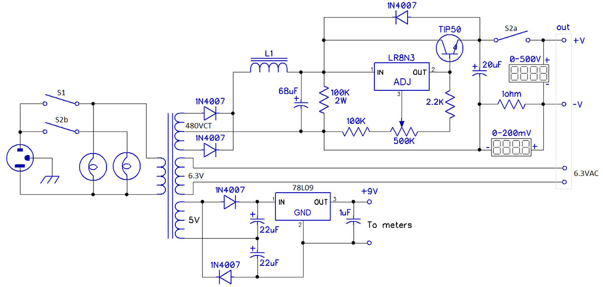
FIGURE 3. Circuit of the entire semiconductor-based power supply.
Implementation
The components in the Parts List may seem a little vague because almost all of them came from my parts pile. The transformer was clearly labeled, but the filter choke was not. I had most of the small parts and ordered only the meters and the high voltage regulator. Various substitutions are, of course, possible.
Most of the supply’s circuitry occupies two small boards, though the transformer and choke take up the most space. One board holds the filter capacitor and the regulator, except for the voltage-adjustment potentiometer. The second board holds the 9V supply for the meters. These are mounted on the back panel of the unit’s enclosure, along with a line connector and three four-pin Jones sockets for the supply’s outputs: the adjustable high voltage and 6.3VAC.
The regulator’s pass transistor is mounted — with an insulator — to the back panel, which acts as a heatsink. Figure 4 shows the back panel with the two boards and the other parts mounted.
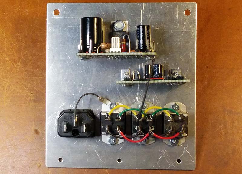
FIGURE 4. The supply’s back panel, with the two circuit boards and connectors.
The front panel holds the two digital meters, the two switches and indicators, and the potentiometer that sets the high voltage. The space between the two panels is mostly occupied by the power transformer and the choke. This transformer’s wires come out the bottom, so it’s mounted on substantial 1/2” standoffs.
A small terminal strip near the back panel holds the two diodes of the half-wave rectifier and connects to the transformer and the choke. Long standoffs join the front and back panels to make the enclosure rigid. Figure 5 shows the inside of the assembled unit.
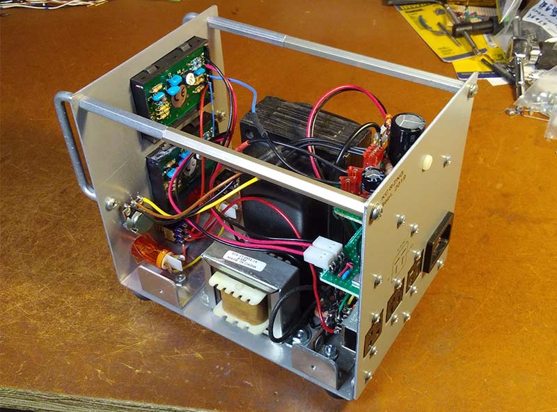
FIGURE 5. The interior of the assembled power supply.
Many wires run between the meters and controls on the front panel and the boards and sockets on the back panel. A better arrangement might have placed the transformer and choke at the back of the enclosure, with the circuitry above or in front of the transformer.
The completed supply’s high voltage can be varied from about 65V up to about 260V. Figure 6 shows the supply being tested; the unit on the right is a tube-based high voltage adjustable load.
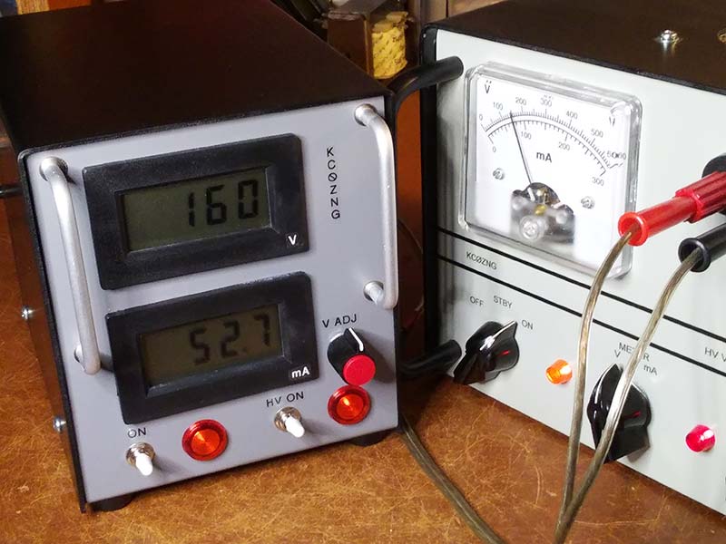
FIGURE 6. The supply under test with an adjustable load.
Observations
Though this supply can provide only limited current, it remains important to attach the pass transistor to an adequate heatsink. Suppose the input voltage to the regulator is 250V, its output is set to 90V, and 50 mA of current is drawn. The transistor must then dissipate (250 – 90) x 0.05 = 8.0W.
On the other hand, the 1Ω resistor through which the output current flows can be small. At 50 mA, the voltage drop through that resistor is only 0.05V, so the power the resistor dissipates is just 0.05 x 0.05 = 0.0025W.
Conclusion
As always, variations are possible. A more robust transformer would allow higher output current. Metering could use LED or analog meters. The parts could be arranged differently, perhaps on a single board. In any case, a utility supply like this has a small footprint on the bench and supports a wide range of experiments with tube circuits. NV
Parts List
1 - 100K, 2W Resistor
1 - 100K, 1/4W Resistor
1 - 2.2K, 1/4W Resistor
1 - 1 ohm, 1/4W Resistor
1 - 500K Linear Potentiometer
1 - 68 µF, 400V Electrolytic Capacitor
1 - 20 µF, 400V Electrolytic Capacitor
2 - 22 µF, 50V Electrolytic Capacitors
1 - 1 µF, 50V Capacitor
5 - 1N4007 Rectifiers
1 - LR8N3 Regulator
1 - 78L09 Regulator
1 - TIP50 NPN Transistor
1 - SPST Toggle Switch
1 - DPST Toggle Switch
2 - 117V Indicators
2 - Digital Meters: 0-200 mV
1 - Power Transformer
1 - Filter Choke
1 - Three-Wire Line Connectors
3 - Four-pin Jones Connectors
1 - Knob
Circuit Boards, Hardware, and Connectors.