A voltage divider is probably the most common electronic circuit. Despite its simplicity, it can be a design challenge for many folks — particularly beginners. This article presents a fast and accurate way to design a variable voltage divider with minimum math.
Figure 1-a shows the problem: Given the potentiometer value RP, calculate the values of RX and RY so that the output voltage can change from -5 to +8V.
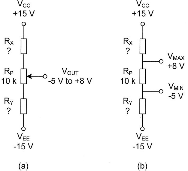
FIGURE 1. Original circuit (a) can be replaced with three fixed resistors (b).
Since the value of -5V will appear at the output when the wiper is at the lower end of the potentiometer and the value of +8V will be there when the wiper is at the upper end of the pot, we can modify the circuit as shown in Figure 1-b.
Let’s take the academic approach first. Write equations for VMAX and VMIN and solve them as a system of simultaneous equations with two unknowns. RX and RY.
By superposition:
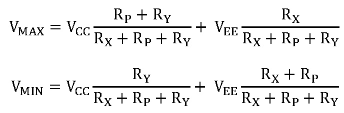
Get rid of denominators and send terms with RX and RY to the left side of each equation:
(VMAX – VEE ) RX+ (VMAX – VCC) RY = (VCC – VMAX) RP
(VMAX – VEE ) RX+ (VMIN – VCC) RY = (VEE – VMIN) RP
Replacing voltages and RP with their numerical values yields:
23RX – 7RY = 70
10RX – 20RY = -100
The solution is RX = 5.385 kΩ and RY = 7.692 kΩ.
We can do the same job faster and with fewer math efforts if we use a little trick: The transfer coefficient of a voltage divider does not change when ALL resistor values are multiplied by a fixed number.
Indeed, if two resistors — R1 = 2 kΩ and R2 = 5 kΩ — are connected to a 9V battery, the output voltage will be:
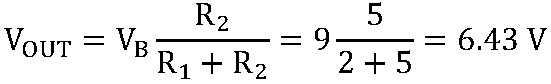
If both resistors are two times larger or three times smaller, the output voltage will still be 6.43V. Let’s apply this to our problem. The first step is to calculate the voltage drops across each resistor as shown in Figure 2-a.

FIGURE 2. Calculation steps include individual voltage drops (a), intermediate resistor values (b), and final circuit (c).
If we assume 1 mA current flows through the network, then RX should have the value of 7 kΩ (7V / 1 mA).
Similarly, RP should have the value of 13 kΩ and RY should be 10 kΩ. Figure 2-b displays the circuit. However, the pot must have the value of 10, not 13 kΩ. To get that, we have to multiply 13 kΩ by 0.769 (10 / 13).
To keep the transfer coefficients of the divider, we multiply the other two resistors by the same number.
Figure 2-c shows the circuit. We get the same result with no superposition and no calculation of simultaneous equations.
Simulation proves that the circuit works as required (see Figure 3).
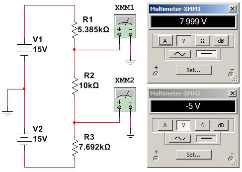
FIGURE 3. Simulation result.
Keep in mind that most potentiometers come with 10 or 20% tolerance; hence, it’s advisable to measure the real resistance RP first and then design the divider using the presented procedure. At the end, match calculated values of RX and RY to a standard resistance series, such as E24 (5% tolerance) or E96 (1% tolerance).
At the end, Figure 4 shows three typical applications of voltage dividers. The first circuit is the front end of almost every digital multimeter (DMM). The analog-to-digital converter inside the DMM has a fixed range of ±1 VDC. The voltage divider extends the measurement range up to 1,000 VDC.
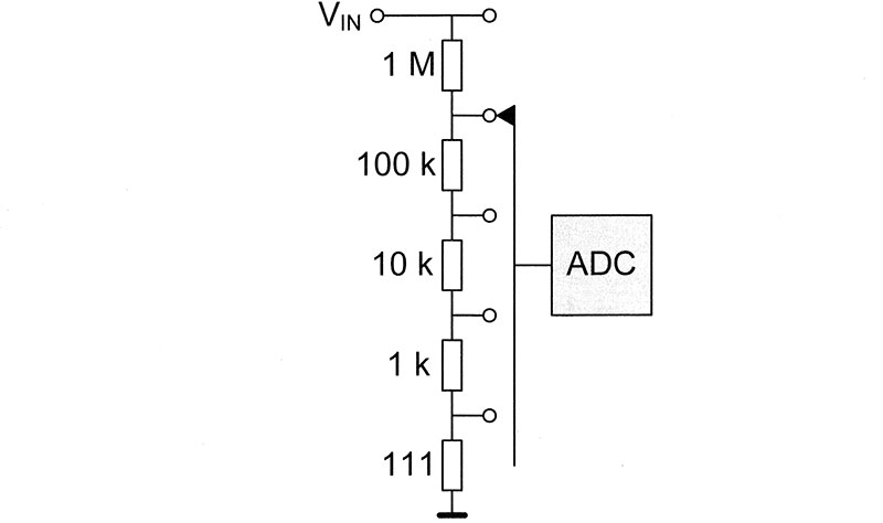
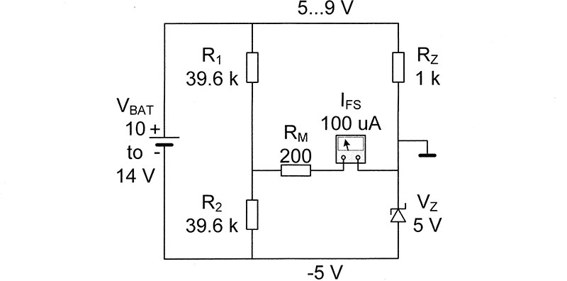
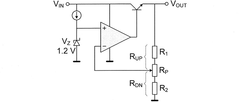
FIGURE 4. Typical applications of voltage dividers.
The second circuit monitors the voltage of a forklift battery with an analog meter. The voltage divider R1-R2 moves the beginning of the meter scale from 0 to 10V. RM sets the end of the scale at 14V. As the scale matches the battery voltage, one can measure that voltage with better resolution.
The third circuit is an adjustable voltage regulator. Because of the variable voltage divider R1-RP-R2, output voltage can be adjusted within a wide range of values using the formula:
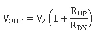
You can quickly design the circuit using the method presented here. NV