After creating an Internet connected digital clock using the Adafruit RA8875 driving an Adafruit seven inch LCD display (Figure 1), my thoughts turned to making a different model that didn’t use a slave Arduino Nano to drive the LCD display. (Refer to my previous article here.) It bothered me that the design required two different microcontrollers to operate. Why couldn’t one microcontroller be used?
My desire was to include several additional features as well, which would require more program space in the microcontroller that drives the LCD display. This new program would also make use of the LCD touch screen to allow a user to select different features of the device.
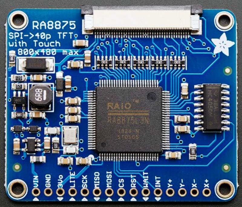
Figure 1. Adafruit RA8875 LCD driver board.
I selected the Arduino MKR Wi-Fi 1010 for replacing the ESP32 and Arduino Nano. It was tested with the RA8875 and LCD connected, and it worked fine. The MKR Wi-Fi 1010 has 256k program space — a vast improvement over the Nano. Plus, it has Internet connectivity. The WiFiNINA library the Wi-Fi 1010 uses for Internet connectivity includes an SSL client which allows access to secure websites.
Using this design, I wrote a lengthy program that included several additional features besides a digital clock: the ability to set an alarm; a countdown timer for uses like monitoring an exercise program; a weather display to provide brief conditions at 10 different cities; a real time stock market report that gives the changing prices for a selection of stocks; and lastly (just for fun), a Mandelbrot fractal generator to produce those wonderful images.
After having built this project with the single Arduino MKR Wi-Fi 1010, I was unhappy with it. Yes, that’s correct, I didn’t like it. The goal of having only one microcontroller in the project was achieved but, in my opinion, it was a mistake. There is something to be said for using a separate microcontroller for Internet connectivity and another one to drive the RA8875 and LCD display.
The microcontroller driving the LCD display doesn’t have to deal with the relatively slow Internet retrieval. Receiving data from the Internet takes some time; at least a fraction of a second and sometimes longer than a second or two. With the digital clock needing to be updated once a second, this can be a problem.
A slow or unresponsive Internet connection also exacerbates this problem. The result is that the clock will hesitate for a few seconds during Internet retrieval before continuing. You can reduce the frequency of retrieving Internet data which makes those interruptions less obvious but, in reality, with something like weather — and especially stock quotes — you want to access the Internet frequently.
There was also another option I wanted to add: an SD card interface to allow me to store and display images on the LCD similar to a photo frame. An SD card interface utilizes the SPI library which is also used to drive the Adafruit RA8875. With Adafruit’s warning about needing to tri-state at least one SPI pin when sharing the SPI interface, a better solution would be a microcontroller with at least two SPI interfaces.
The Teensy 3.5 microcontroller looked like a good choice since it has three SPI interfaces, with one used by the built-in microSD card socket. It also has 512k Flash memory, 120 MHz clock speed, and is compatible with the RA8875 driving the LCD. The Arduino MKR Wi-Fi 1010 could still be used for the Internet connectivity, but an ESP32 has a faster clock speed and is one third the cost.
A last-minute addition to this project was to add Internet radio. With the ESP32 being able to stream radio stations off the Internet, all that was needed was a hardware MP3 decoder and an audio amplifier.
Both of these devices are available on small breakout boards and with the addition of a pair of two inch speakers, it was possible to squeeze everything into the case I had already 3D printed. A VS1053 board was used for the MP3 decoder (labeled from LC Technology; see Figure 2) and is available from Amazon or eBay.
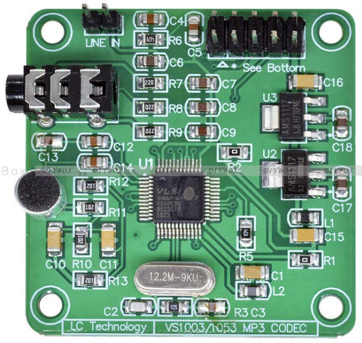
Figure 2. VS1053 MP3 Codec board.
Also from Amazon or eBay, is a very small stereo audio amplifier board with a built-in switch and volume control, using the PAM8403 circuit and running off a single five volt supply; refer to Figure 3. This was adequate for driving two small speakers.
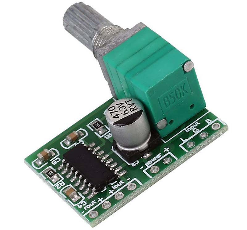
Figure 3. PAM8403 five volt stereo audio amplifier.
This board measures only 29 x 20 mm. Because the wall thickness of my project box is almost 5 mm and the threaded portion of the potentiometer was only about 5.5 mm, I elected to epoxy the potentiometer into a hole on the box face.
Instead of having the ESP32 sending updated information to the Teensy 3.5 on a regular schedule, the Teensy 3.5 sends requests for specific data to the ESP32. The ESP32 waits for these requests and when one arrives, it fetches the information from the Internet and returns it to the Teensy in a concise data string.
It’s similar to a simple client-server architecture except the two microcontrollers are connected by their serial ports running at 38,400 baud. Serial3 on the Teensy 3.5 is connected to Serial2 on the ESP32 (Figure 4).
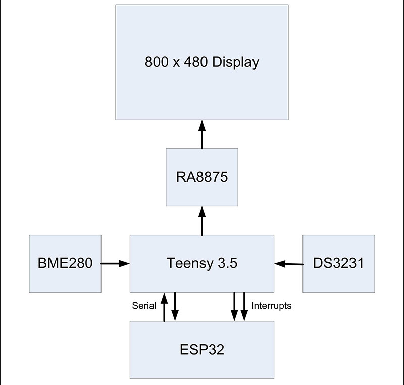
Figure 4. Block diagram of the Super Clock circuitry.
The request strings the Teensy 3.5 sends to the ESP32 are:
- Time: Requests the current time from a Network Time Protocol server.
- Home: Requests a brief weather summary for a chosen home location.
- Weather: Requests a brief weather summary from 10 different locations.
- Stock: Requests a stock market price for 10 specific stocks.
- Radio: Starts a download stream from an Internet radio station. (See the sidebar for more on the Internet radio.)
When one of these request strings is received, the ESP32 sends its request through the Internet for the appropriate data. When the data is received, it’s parsed and then sent to the Teensy 3.5 as a concise string, which is then parsed by the Teensy to retrieve the data it requested.
While this might seem a little convoluted, it leaves the ESP32 waiting for the response from the Internet while the Teensy program can continue and update the clock display every second with time to spare. The ESP32 also continuously checks that it has Internet connectivity from the wireless router it’s using. If it loses its connection, it goes into a loop to reconnect.
My Implementation of Internet Radio has Limitations
When the Teensy 3.5 sends a radio string, the ESP32 connects to the current radio station and then enters an endless loop to read the continuous stream of the digitized radio signal sent from the Internet.
At this point, the ESP32 can’t read any requests sent from the Teensy 3.5 since it’s locked in the tight loop to read the radio stream. The only way to break out of the loop is through an external interrupt request.
The same is true when changing a station, where we break out of the stream loop, change the station (and therefore the URL of the new data stream source), and then re-enter the stream loop.
The Teensy pin 14 is tied to the ESP32 pin 13, and pin 17 is tied to 14. You only need to go from a HIGH to a LOW state on pin 14 or 17 of the Teensy 3.5 for a few milliseconds to initiate an interrupt on the ESP32:
// External Interrupt on pin 13 - turns off radio
void IRAM_ATTR stop_radio_Int()
{
radio_on = false;
digitalWrite(TEST, LOW);
}
Note that the interrupt routine just sets radio_on = false;. The digitalWrite(TEST, LOW); statement turns off an LED for debugging — it proves the interrupt happened. With the radio_on value being false, the while(radio_on) loop is stopped and the radio data stream is no longer read.
Interrupts are attached to pins 13 and 14 on the ESP32 for breaking out of the radio stream loop and changing a station, respectively. Note that you can’t use pin 12 on the ESP32 for an interrupt on this project.
When you try to download a program into the ESP32, pin 12 will be held HIGH by the Teensy 3.5 in its default state unless you remove it from its socket on the PCB. With pin 12 held HIGH, the ESP32 will not be able to receive a download.
It should also be noted that while the radio is playing, you can exit the radio menu and return to the default time and date screen, but there will not be any updates of the weather or the time from the Internet.
The weather mode and stock market mode will also not work, as the full time of the ESP32 is occupied with reading the radio stream. These functions will be available again once the radio is turned off.
Software
A flowchart for the ESP32 program is shown in Figure 5 and the Teensy 3.5 program in Figure 6. The bulk of the software resides in the Teensy 3.5 — about 2,000 total lines, including blanks and comments. However, that only uses 14% of the program space available.
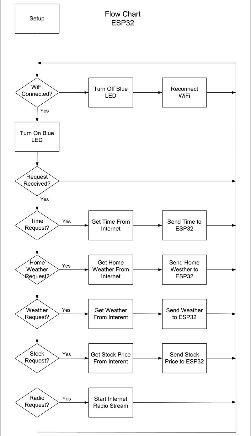
Figure 5. Flowchart of the ESP32 program.
The flowchart in Figure 6 is a lot more involved than that for the ESP32.
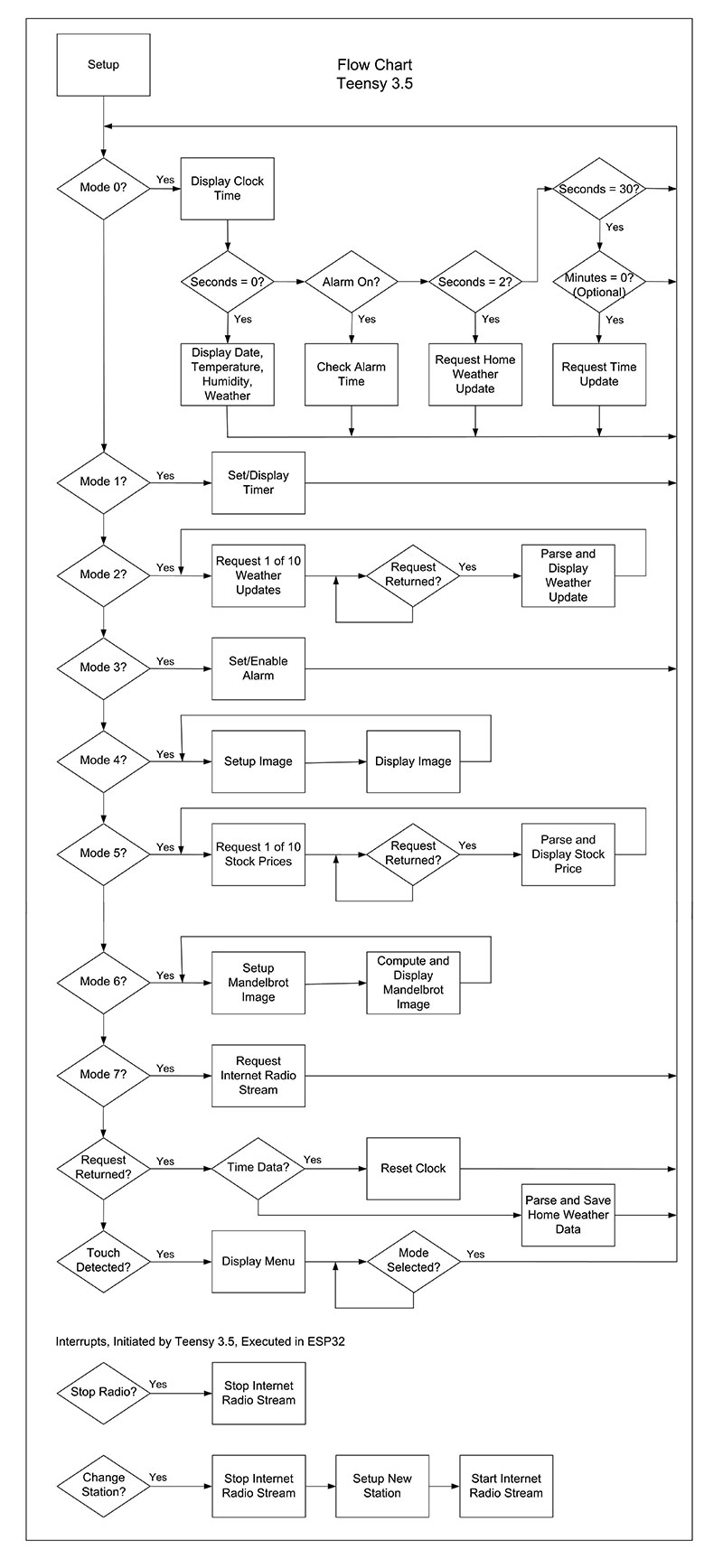
Figure 6. Flowchart of the Teensy 3.5 program.
The vast majority of the Teensy program code deals with writing to the LCD screen and reacting to the touch screen. Moving from graphic to text mode has a lot of overhead. After declaring text mode, you must set the size, set the color, place the cursor where you want to write the text, and then finally write the text from a character array.
The library for the RA8875 LCD driver also requires a character array when writing text on the screen which can be awkward. A string would have been preferred.
The software for both the Teensy 3.5 and ESP32 can be found in the download section for this article. Both programs contain several comments and Serial.print statements to help with understanding and debugging.
I used the Arduino IDE (integrated development environment) for programming. You need to have the ESP32 board by Expressif systems (https://www.espressif.com/) and the Teensy boards (Teensyduino) by PJRC installed in the Arduino IDE. You can find a good help document on this at https://cdn-learn.adafruit.com/downloads/pdf/add-boards-arduino-v164.pdf.
Both programs also use several included libraries. These libraries must be resident in the Arduino IDE to be able to compile the two programs. If you need help with this, refer to https://www.arduino.cc/en/reference/libraries. There’s a link on this web page for instructions to install libraries.
The Teensy 3.5 program operates in eight different modes. For example, Mode 0 displays the default time, temperature, humidity, and weather screen, while Mode 1 allows you to set and display a timer. A description of what each mode does follows.
Mode 0
Mode 0 is the default mode and does a lot of additional things besides displaying the time in large numbers at the top of the LCD display. One of the little tricks in this program is to only draw one of the large numbers if it changes. If we re-draw every number, it takes too long, and the result is a noticeable flicker in the time display. During seconds 0 through 3, we do specific things. Otherwise, we just wait for the next second to occur and then redraw the time:
- Second 0: The date, local temperature and humidity, and brief local weather conditions are redrawn. The entire bottom half of the screen is redrawn.
- Second 1: It next checks to see if an alarm has been set. If this is true, it checks for the correct alarm time and issues an alarm if a match is found.
- Second 2: A Home request is sent to the ESP32, asking for an update to the local weather.
- Second 30: A Time request is sent to update the time from the Internet. There is a commented-out line in the code here to send the request only once an hour.
After this, it breaks out of the switch statement that decodes the different modes and then checks to see if the screen has been touched, which would then jump to a menu screen.
Lastly, we check to see if our Home or Time request has been answered. If it has, then the data from the ESP32 is parsed and stored in the case of a Home request, or the time is reset if there’s a Time request.
If the LCD screen is touched while in Mode 0, it will display a simple menu screen allowing the mode to be changed. Touching the LCD screen or an Exit button when in one of the other modes will return you to Mode 0.
Mode 1
Mode 1 allows you to set a timer and then display it. This can be used to time an activity like an exercise program, for example. The set time counts down using the same style large numbers for the normal time display in Mode 0. At the end of the countdown, the alarm line is toggled and the radio turned on. A keyboard is displayed for entry, along with buttons to start the timer or exit.
Mode 2
The weather at 10 different chosen locations is displayed. The format is the same as the local weather display in Mode 0. The screen fills with the first five locations and then clears and displays the second five. The display hesitates between drawing each brief weather condition as a request is made to the ESP32 for each location, and then waits until the ESP32 returns the weather data.
The API of the api.openweathermap.org site is used to obtain the weather information. Their website gives the details of how to use their site. The service is free, but you do need to register and get a key to use when making requests to their server.
This program uses a very simple type of request for specific towns. The numbers used for thousands of towns around the world are also available on this site. A zip code can be used, but this defaults to the nearest National Weather Service Forecast Offices, which only number 122 for the entire United States.
Mode 3
A traditional alarm is set and turned on and off in this mode. A time is entered, along with an a.m. or p.m. choice, and the alarm turned on or off. When the clock reaches the alarm time, the alarm line is toggled, and the radio turned on — a gentle way to produce that awful sound every sleeping person dislikes. The setup interface is similar to the one used by the timer.
Mode 4
Setting this mode displays a series of bitmap images that are stored on a microSD card. The Teensy 3.5 has a slot for the microSD card on the end opposite of the USB connector. These bitmap images can be any size that doesn’t exceed the LCD screen size. I purposefully made mine exactly 800x480 pixels. File names need to be restricted to eight characters and adhere to the 8.3 file naming system.
Using the program example Adafruit supplied with the RA8875 library for reading bitmaps from an SD card, it takes about 30 seconds to write the 800x480 pixel image to the screen. This is not surprising since the image is drawn pixel by pixel. With the drawPixel method commented out, the bmpDraw method only takes 1.25 seconds to read and decode the image.
Mode 5
This mode does something similar to Mode 2, except it displays 10 different stock quotes in real time. The stocks were selected and their symbols added to the ESP32 program.
When a Stock request is sent to the ESP32, it uses the API of the www.alphavantage.co website. This site requires an SSL connection for security and the ESP32 uses the WiFiClientSecure library for this.
The number of options this site has for requesting data is almost overwhelming. I chose something simple, and although it sends a compact format, there is still a lot of information returned. I only extract the current price, but there is a lot more potential here. The program loops through the 10 chosen stocks and displays the current price. It then clears the LCD and repeats the display.
Mode 6
For my own amusement, I also included a function that draws 10 different Mandelbrot fractal images on the screen at a size of 480x480. I’ve been writing software to compute Mandelbrot images since the August 1985 issue of the Scientific American revealed them to the public. These have been my “Hello World” programs whenever I learned a new programming language. My millennial son says these images on the LCD make the best night light he’s ever had!
Mode 7
In this mode, an Internet radio station is streamed and decoded by the VS1053 breakout board. Five different stations are stored and can be selected from the Radio menu. Turning the radio on and off can only be done through the Radio menu.
Figures 7-16 show the various screen images for the different modes.
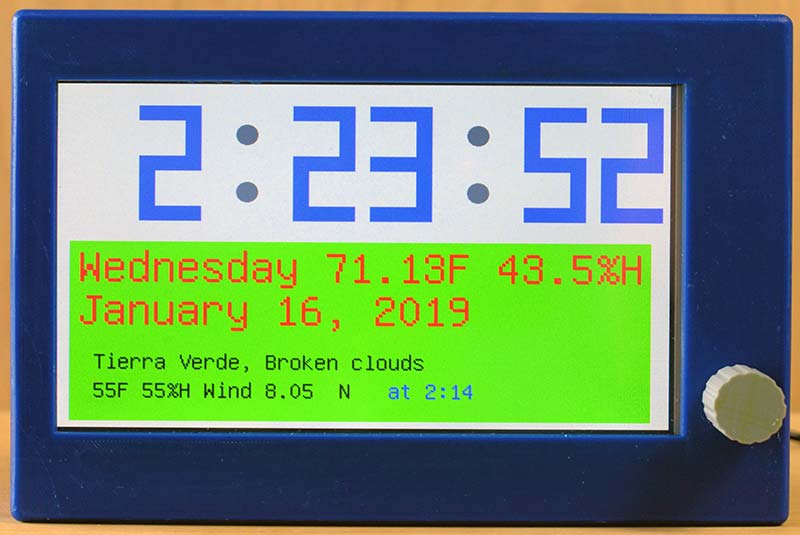
Figure 7. Mode 0: Default time, date, weather display.
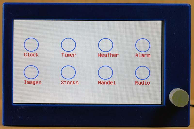
Figure 8. Touch menu.
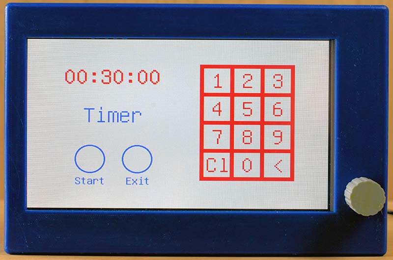
Figure 9. Mode 1: Timer setup screen.
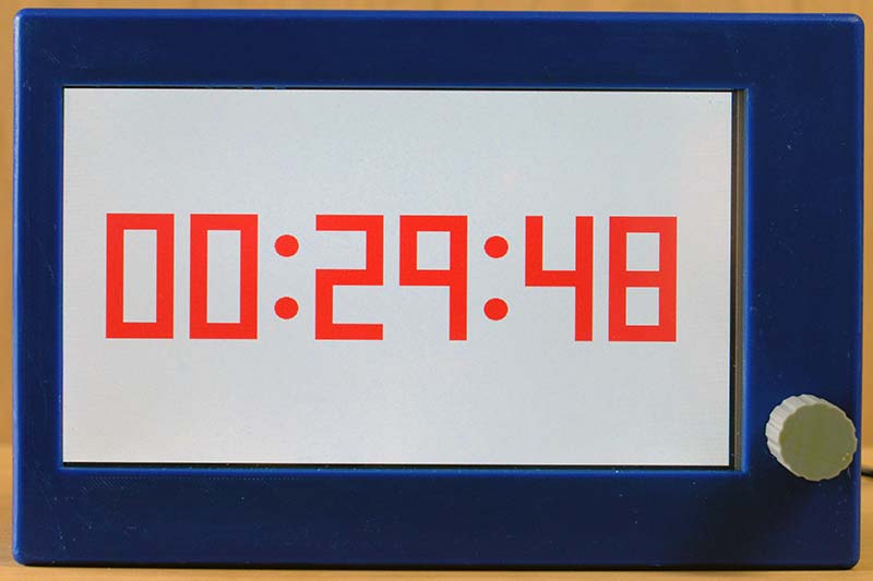
Figure 10. Mode 1: Timer screen.
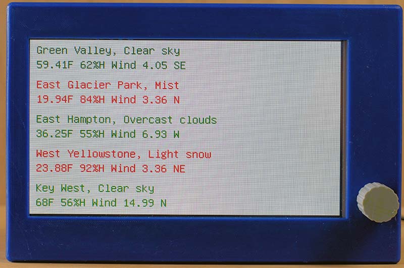
Figure 11. Mode 2: Weather screen.
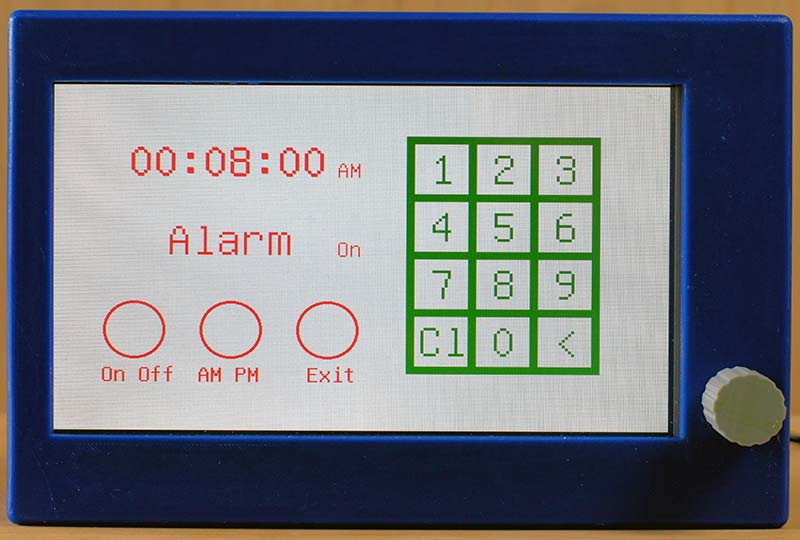
Figure 12. Mode 3: Alarm setup screen.
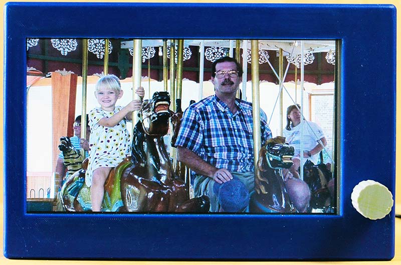
Figure 13. Mode 4: Display photographs.
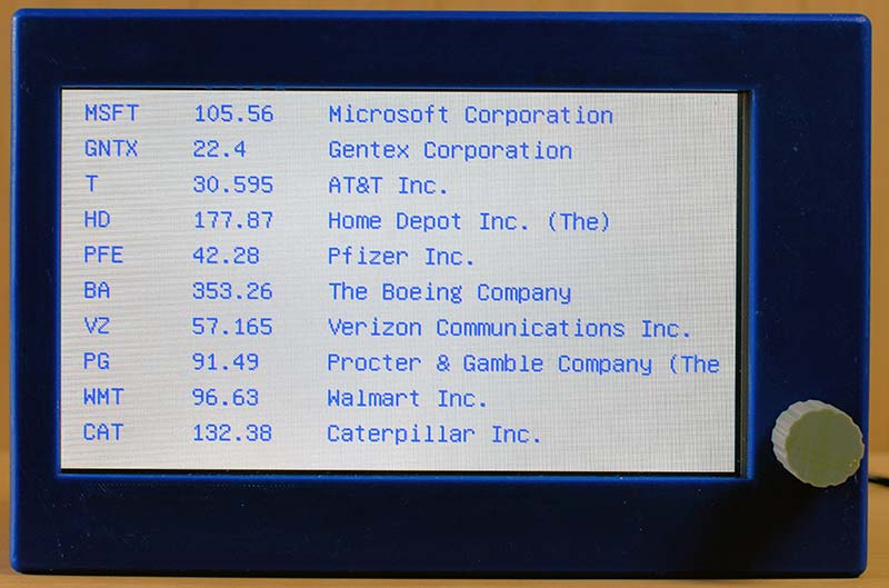
Figure 14. Mode 5: Stock prices screen.
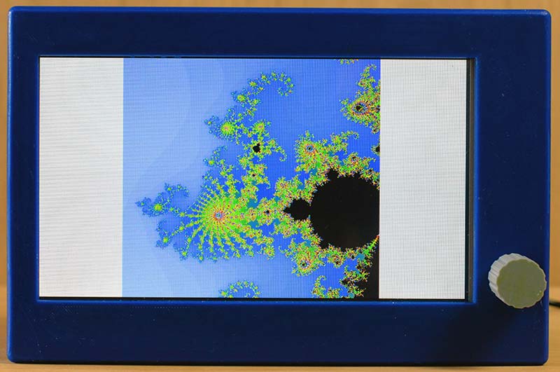
Figure 15. Mode 6: Display Mandelbrot fractal images.
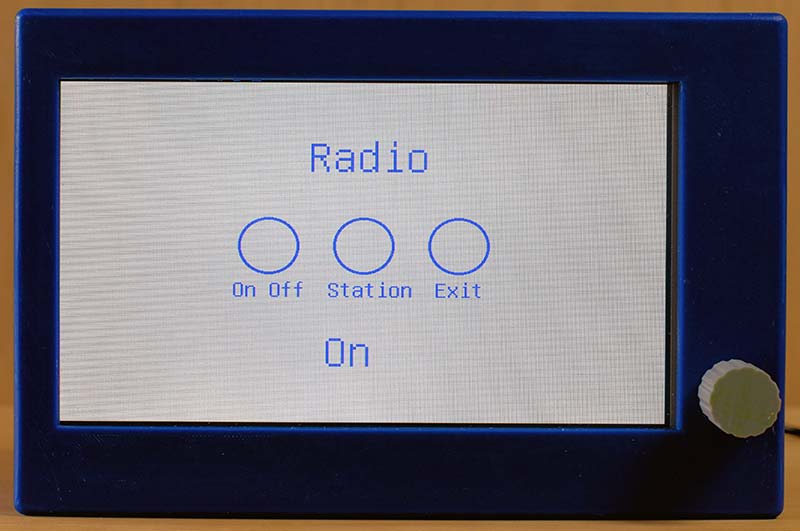
Figure 16. Mode 7: Radio menu.
Hardware and Construction
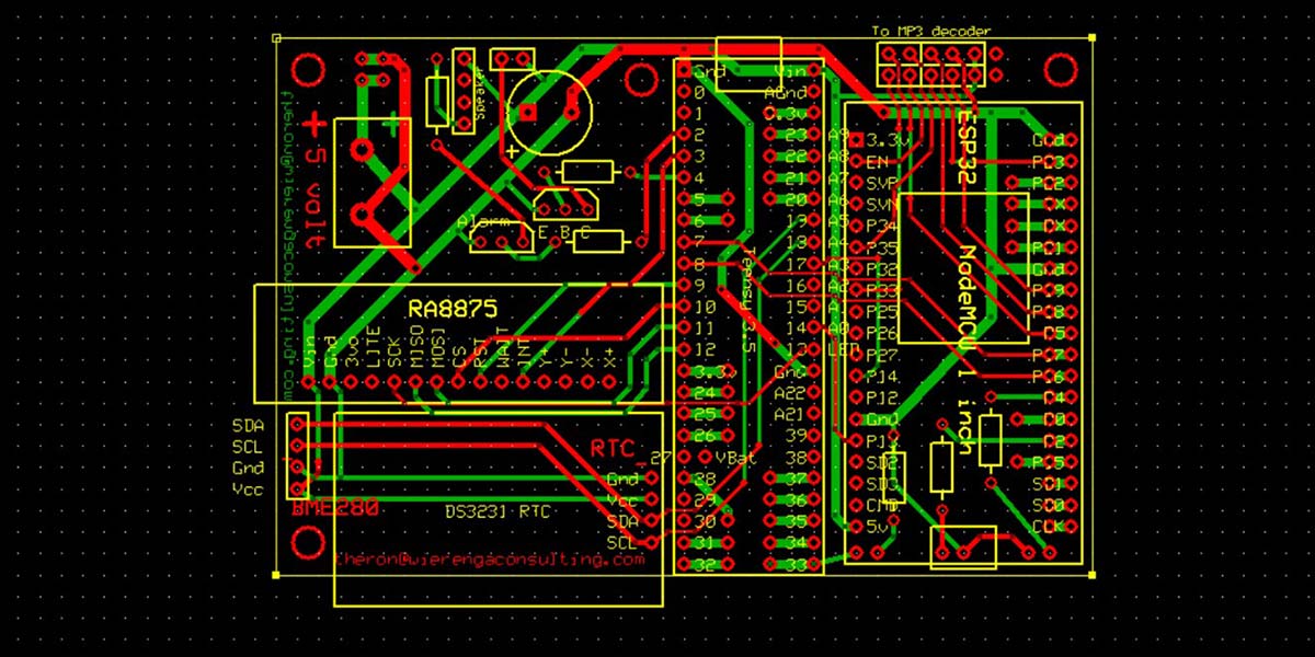
The schematic for the Super Clock is shown in Figure 17. A printed circuit board (PCB) was created because of the many connections needed.
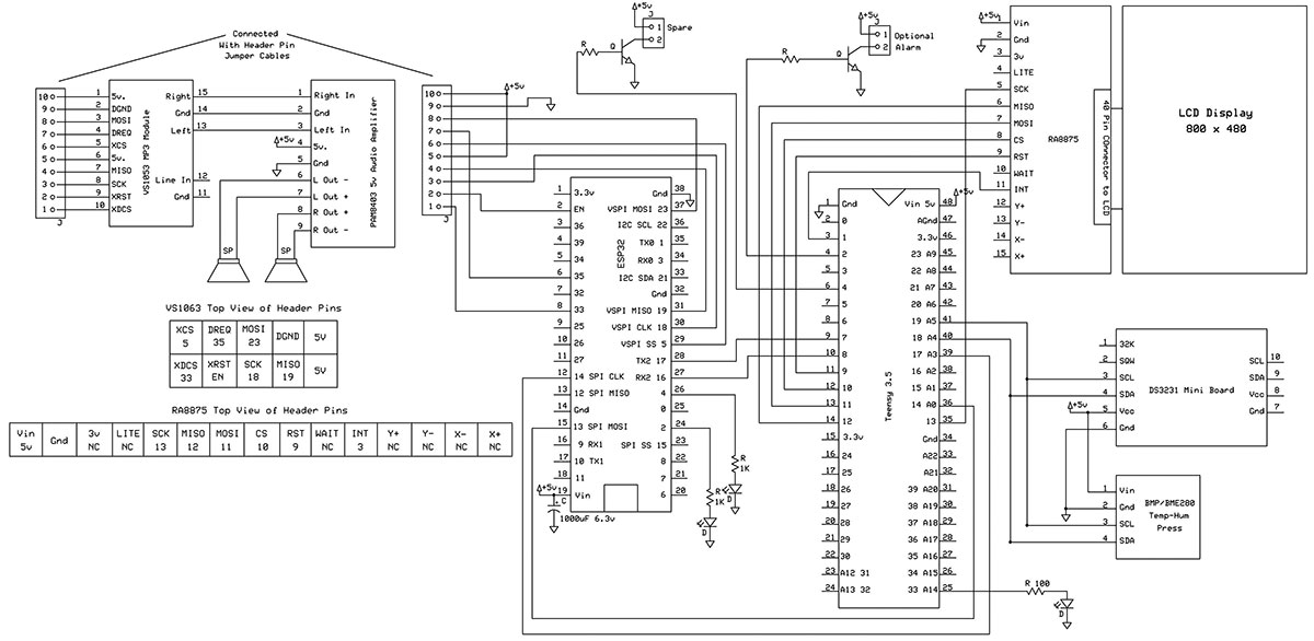
Figure 17. Schematic of the Super Clock.
I use ExpressPCB for this service and was just able to fit what was needed on their 3.8 x 2.5 inch Miniboard. An ExpressPCB file is included in the download area. You can download the free Express PCB software (www.expresspcb.com) and view or print the PCB layout.
This PCB mounts the Teensy 3.5 and ESP32 along with a few other parts. In addition, it also has connectors to five other small breakout boards. These are the: RA8875 LCD driver; BME280 temperature and humidity sensor; DS3231 real time clock (RTC); VS1053 MP3 decoder; and the PAM8403 audio amplifier. The PCB pads for the ESP32 have been doubled up on one side allowing the use of an ESP32 with pin spacing across the board of either 0.9 or 1.0 inches wide.
Be sure to check that the ESP32 you have is pin compatible with this design which has 38 pins. Consider also the board size of the ESP32 and make sure it will not interfere with the nearby header pins that go to the MP3 decoder board. I used the HiLetgo ESP-WROOM-32 ESP32 ESP-32S development board.
Pins 2 and 4 on the Teensy 3.5 have been brought out to drive an NPN transistor. One of these can be used to drive an optional speaker for the clock alarm or timer and the other is a spare. I also elected to turn the radio on for the alarm or timer ending. Additional unused pads of both microcontrollers were also brought out on the PCB for optional future use.
There are places to mount three LEDs: one from the Teensy connected to pin 33; and two from the ESP32 connected to pins 2 and 4. These can be used to denote a good Internet connect or other testing or debugging functions.
The DS3231 RTC board mount is a tight fit. A four-pin header was added to the unused through holes on the opposite end from the provided header which was cut down to allow a fit. This also allows the onboard battery of the RTC to face up for easier removal.
The RA8875 LCD driver board is also a tight fit. There is a hole for a 4-40 machine screw on the PCB near pin 1 of the Teensy 3.5; a single stand-off was used here to mount the RA8875 driver board under the main PCB. Unfortunately, the Adafruit RA8875 board uses 2-56 size mounting holes, so a small printed tab with 2-56 and 4-40 holes was 3D printed to connect the RA8875 board to the 4-40 stand-off beneath the main PCB. This is illustrated in Figure 18.
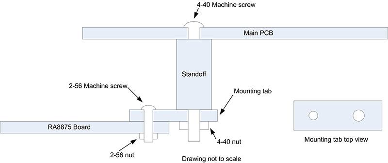
Figure 18. Mounting method for RA8875 board.
Short six-pin jumpers were used to connect the headers on the RA8875 driver board to identical headers on the main PCB. There is a four-pin header to connect the tiny BME280 board via a jumper. This jumper is brought out the back of the project box so the BME280 is not affected by any heat from the circuitry inside the box.
The VS1053 MP decoder and the PAM8403 audio amplifier are also on separate small breakout boards. There are two stand-offs to mount the VS1053 MP decoder in the project box. All the stand-offs have holes in them sized for a 4-40 machine screw tap. Be careful when tapping these as they can be split if you tap too far down.
I used 1/4 inch long 4-40 machine screws when attaching the VS1053 MP decoder. Six-pin jumpers were also used here to connect the VS1053 MP decoder to the main PCB, although only five of the pins are used on each jumper. I originally soldered headers onto the PAM8403 audio amplifier to make connections to the speakers, five volt power, and the VS1053 MP decoder. These small headers can very easily make poor connections. My recommendation is to solder connecting wires directly to the PAM8403 audio amplifier board.
The audio lines out of the VS1053 MP decoder are connected to a mini stereo jack, so a mini stereo plug was used, and its wires connected to the PAM8403 audio amplifier. I used screw-down connectors to attach the wires from the five volt power jack on the back panel. These wires could be soldered directly to the PCB.
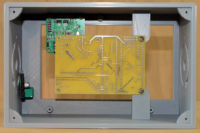
Figure 19. A 3D printed project box showing placement of prototype PCB, VS1053 MP3 decoder, and PAM8403 audio amplifier.
For the project box itself, I designed and used my 3D printer to produce the custom design. Sketchup files along with object files are included in the download material. Also included are a back cover, the tabs for mounting the LCD display, the knob for the audio amplifier, and the tab to connect the RA8875 to the stand-off.
The object files can be used with the Cura slicer to produce gcode for many different 3D printers. I recommend this custom project box — especially because of the difficulty in mounting the Adafruit LCD which has no mounting holes or tabs whatsoever, making mounting a real challenge.
The project box mounts the LCD by placing it between three 1/4 inch stand-offs which then have small 3D printed tabs screwed down on the top of the stand-offs to press the LCD against the box wall.
Care needs to be taken to not press down on the LCD display too hard as the touch panel may register a continual touch, making reading it impossible. In retrospect, this box should have been made larger, allowing for an easier fit of the components. The two inch speakers just fit; anything larger will require a larger project box.
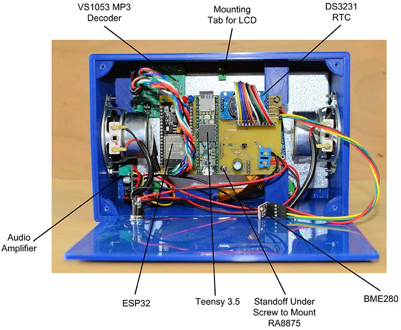
Figure 20. Interior of a completed Super Clock.
A skilled builder could eliminate the PCB and use a breadboard with solder pads as well as a standard project box, but it will be a challenge — especially the mounting of the LCD display.
Conclusion
In reviewing the two programs that run this project, a lot more time could be spent on giving them more polish. No doubt programmers with more skill and artistic talent than I have could improve the overall appearance of the individual screens. The Internet radio portion of the code could also use some improvement, like displaying the radio station.
Inexpensive microcontrollers have completely changed the way digital clocks are designed. With the introduction of built-in wireless Internet in microcontrollers like the ESP32, another wave of changes in the design of digital clocks with added features is possible.
With the added Internet access, the list of possible additions has greatly expanded. It would not be too difficult to add to this project functions like scrolling news reports, farm market prices, weather maps (a bit of a challenge and no doubt slow), traffic reports or maps, and sports scores to name a few.
Given the program size available on both the ESP32 and Teensy 3.5, I suspect most of the ideas mentioned above could be programmed into this project without any hardware changes.
It’s true. I’m the fellow in the joke, “Ask him the time and he’ll tell you how to build a clock.” NV
The great thing about having an Internet connected clock is that you never need to set it, and its accuracy is always good to a second or two. The breakout board for the DS3231 has a built-in socket for a CR2025 coin battery. When power is removed, this battery keeps the DS3231 running and the time is preserved.
The DS3231 is very accurate and will only vary plus or minus a minute in a year. Daylight Savings Time does require us to reset our clocks twice a year, and this will be done automatically when the correct time is received from the Network Time Protocol server. The default code resets the clock every minute. The code that does this can be modified to reset the time every hour:
// Second 30, Request the time each minute or once an hour
// if ((last_sec == 30) && (now_time.minute() == 0))
if (last_sec == 30)
{
Serial3.println(“Time\n”);
Serial.println(“Time request sent”);
}
You can comment-out the line checking for the “last second equals 30” and uncomment the one above to have it check every hour. If the default is used, you don’t need to set the DS3231 the first time the program is run. Whatever time and date the DS3231 starts with will be reset to the correct time the next time it is at second 30 and you have an Internet connection.
Later on in the program after the Time request has been sent, the program will call the check_incoming() function for a concise time string. The parsed second, minute, hour, etc., are then used from this string to reset the clock with the rtc.adjust function:
rtc.adjust(DateTime(iyear, bmonth, bdayOfMonth, htemp, mtemp, stemp));
Note that you will possibly need to adjust the initial constants for your time zone at the top of the Teensy 3.5 program:
// Time server
const char* ntpServer = “pool.ntp.org”;
const long gmtOffset_sec = 3600 * -5;
const int daylightOffset_sec = 3600;
The pool.ntp.org address doesn’t need to be changed. The gmtOffset_sec value should reflect your time zone; mine is Eastern Standard Time, which is five hours less the Greenwich Mean Time; thus, the 3,600 seconds in an hour multiplied by -5.
The area I reside in observes Daylight Savings Time, so the daylightOffset_sec value is set to one hour or 3,600 seconds.
Parts List
| ESP32 38-pin NodeMCU-32S |
eBay, Amazon |
| 40-pin IC socket, cut lengthwise for correct ESP32 spacing |
eBay, Amazon |
| Yellow four-digit seven-segment LED display (2) |
Electronic Goldmine |
| DS3231 RTC module |
eBay, Amazon |
| BME280 temperature/humidity module |
eBay, Amazon |
| LCD display, four-line/20-character with I2C interface |
eBay, Amazon |
| 74HCT138, SMT, SOIC, 0.05 inch pitch |
eBay, Amazon |
| 2N3906 PNP transistors (8) |
eBay, Amazon |
| 1K 1/8 watt resistors (9) |
eBay, Amazon |
| 1,000 µF, 6.3 volt electrolytic capacitors (2) |
eBay, Amazon |
| Blue LED |
eBay, Amazon |
| Header pins |
eBay, Amazon |
| Header pin sockets |
eBay, Amazon |
| Header pin jumpers |
eBay, Amazon |
| SPST switches (2) |
eBay, Amazon |
| Five volt/minimum one amp wall wart type power supply |
eBay, Amazon |
| Mating power jack for power supply |
eBay, Amazon |
| Various screws, nuts, stand-offs, solder, hookup wire, shrink tubing |
Home Depot, Lowe's |
| Project box, 3D printed |
Files provided in download area |
Downloads
What’s in the zip?
Express PCB files
Source Code
Object Files
SketchUp Files