Having read about the ESP8266 NTP clock in previous issues of Nuts & Volts, an idea came to mind to construct an interface camera using the ESP8266. We succeeded in building a live webcam using the ESP8266 Wi-Fi webserver, and would like to share our experience with you!
Basically, to construct a Wi-Fi live webcam, we needed a Wi-Fi server interfaced with a camera. This kind of server is nothing more than a Wi-Fi server built around an ESP8266. Constructing an ESP8266 Wi-Fi server is not difficult. Just like in the NTP clock design, we also used the Arduino IDE (integrated development environment) for compiling the Wi-Fi server code we wrote and fused it into the ESP8266.
Sometimes it can be very difficult to interface commercially-available USB cameras to ESP8266 microcontrollers. For this, we needed a suitable driver for the camera and had to write OS for the microcontroller to use with the driver. It’s a very cumbersome job for the average programmer.
To overcome this difficulty, we used a different approach and focused on using the camera in Android phones. We didn’t need any OS and driver for the camera because they’re built inside. The only thing we had to find was a way to interface it with the ESP8266 Wi-Fi webserver. The details of our approach are discussed below.
Interfacing with the ESP8266 Wi-Fi Webserver
First, we converted the Android Wi-Fi camera server by writing a suitable mobile app. To do this, we used the Android Studio tool. We’ll explain this in detail shortly.
Second, we connected the Wi-Fi camera server (built with the Android phone) to the local Wi-Fi network by using the Android Settings icon and entering the SSID and password of the Wi-Fi modem/router that is connected to the Internet. Once the phone is connected to the Wi-Fi camera server, it’s also connected to the Wi-Fi network.
Third, the Wi-Fi webserver built with the ESP8266 is also connected to the same local Wi-Fi network, using the same SSID and password. The method on how to enter the SSID and password to the ESP webserver will be explained momentarily.
Since the camera and ESP8266 server are connected to the local Wi-Fi network, interfacing the camera with the ESP8266 is very simple; just feed the displayed camera URL from the Android phone to the Wi-Fi webserver. The method for how this is done will also be explained later.
In this situation, the ES8266 webserver will act in a dual role. It will be a wireless client to the camera server as well as a wireless webserver to the outside world. This design comprises three parts: building the ESP8266 Wi-Fi webserver; building the mobile app (usually called the camera server app); and testing and interfacing.
Building the Wi-Fi Webserver
The ESP8266 module is gaining popularity in the field of electronics because it’s affordable, reliable, and readily available. The ESP8266 Wi-Fi module contains a 32-bit low power CPU, ROM, and RAM. The ESP8266 is a complete and self-contained Wi-Fi network solution that can run stand-alone or connected to a microcontroller. Unfortunately, most of the documentation is in Chinese and the information provided in the datasheet is lacking in practical details. To help fill this gap, an ESP8266 community forum has been established.
Schematic
The circuit schematic is shown in Figure 1. We used the ESP826612E module as a stand-alone device. The supply voltage for the Wi-Fi module is 3.3 volts. A USB-to-serial module (CP2102) is used for connecting the TX and RX pins to a PC for communications and programming. The CP2102 can work with either 5V or 3.3V. For our purposes, we used the 3.3V option. You can use any 3.3V USB-to-serial converter that you prefer.
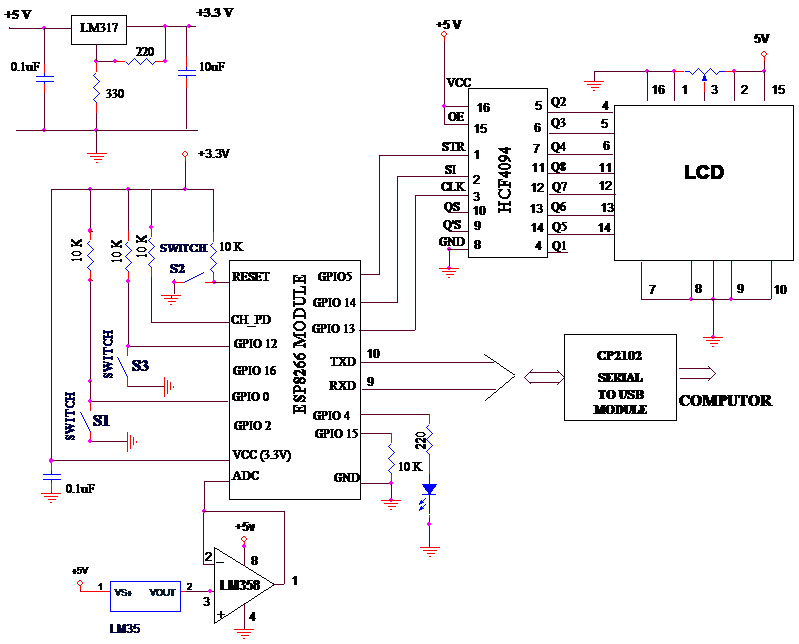
Figure 1. The hardware circuit.
The driver software associated with the USB-to-serial converter has to be installed in the PC for communications. Table 1 shows the connection details between the converter and the ESP8266 board.
The ESP826612E module only has 16 output pins for use. The reset pin is connected to the supply through 10K resistance, and a pushbutton (S2) is provided for manual reset.
| 3.3V USB-TO-SERIAL CONVERTER |
ESP8266 BOARD |
CP2102 (USB-TO-SERIAL) USED IN THE PROTOTYPE |
| 1 TX PIN |
RX PIN |
TX PIN |
| 2 RX PIN |
TX PIN |
RX PIN |
| 3 +3.3V PINS (SUPPLY PIN) |
3.3V SUPPLY |
+33V PIN (+5V PIN NOT USED) |
| 4 GROUND |
GROUND |
GND |
Table 1. Connection details between the USB-to-serial converter and ESP8266 board.
The programming mode pin GPIO0 is connected to the supply voltage via the 10K resistor, and a pushbutton (S1) brings the module to the programming mode.The CH_PD pin is connected to the supply via the 10K resistor.
The ESP8266EX also integrates a general-purpose 10-bit resolution ADC (analog-to-digital converter). The ADC range is from 0V to1.0V. It’s typically used to measure the voltage from the sensor or battery. The ADC can’t be used when the chip is transmitting.
All digital I/O pins are protected from over-voltage with a snapback circuit connected between the pad and ground. The snapback voltage is typically about 6V, and the holding voltage is 5.8V. This provides protection from over-voltage and ESD (electrostatic discharge). The output devices are also protected from reverse voltage with diodes. The setting pin GPIO12 is connected to the supply voltage via the 10K resistor, and a pushbutton (S3) is used to bring the module to set mode to establish the SSID, password, and camera URL.
An LED is connected to GPIO pin 4. Suppliers of Wi-Fi modules follow a different pattern for output pin arrangements. So, we used the ESP826612E module and designed a PCB (printed circuit board) to suit our requirements. We chose this module because more GPIO pins are accessible for users. The circuit is simple; you can easily wire it up and do the design.
Due to limited output pins, we implemented a simple application to measure the room temperature using an LM35 temperature sensor and ON/OFF LED control. Output pin 2 of the LM35 is connected to the ADC pin of the ESP8266 through the unity gain amplifier LM358 which acts as a buffer. The LM358 is a calibrated temperature sensor; the sensitivity is 10 millivolts/10C.
The circuit board is shown in Figure 2. The LCD is interfaced using the eight-bit shift register CD4094 to display the IP Address. The LCD is operated in four-bit mode.
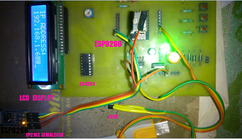
Figure 2. Our prototype.
Table 2 shows the complete connection details between the ESP8266 and the external components: LCD, CD4094, LM35, LM358, and pushbutton switches S1, S2, and S3.
| ESP8266 (COMMERCIAL BOARD) |
PUSHBUTTON SWITCH |
LCD (2x16) |
CD4094 SERIAL-TO-PARALLEL SHIFT REGISTER |
LM358 OP-AMP |
LM35 |
| GPIO 12------➔ |
S3 |
|
|
|
|
| GPIO 0--------➔ |
S1 |
|
|
|
|
| RESET--------➔ |
S2 |
|
|
|
|
| GPIO 5---------- |
---------------- |
------------➔ |
STR(1) |
|
|
| GPIO 14-------- |
---------------- |
------------➔ |
SI or DATA (2) |
|
|
| GPIO 13-------- |
---------------- |
------------➔ |
CLK (3) |
|
|
| |
|
RS(4)----➔ |
Q2(5) |
|
|
| |
|
R/W(5)--➔ |
Q3(6) |
|
|
| |
|
EN( 6)---➔ |
Q4(7) |
|
|
| |
|
D4(11)---➔ |
Q8(11) |
|
|
| |
|
D5(12)--➔ |
Q7(12) |
|
|
| |
|
D6( 13)-➔ |
Q6(13) |
|
|
| |
|
D7(14)--➔ |
Q(14) |
|
|
| ADC ----------- |
---------------- |
-------------- |
-----------➔ |
OUTPUT1(1) |
|
| |
|
|
|
INPUT+(3) -➔ |
VOUT(2) |
| Note: Some commercial boards have the reset and GPIO0 pin readily available for use. If these pins are not available, just follow Table 2 |
Table 2. Connection details between the ESP8266 and external components.
Software Programming
We use the Arduino IDE for compiling and loading programs. The ESP8266 community has developed a suitable plug-in for the ESP8266 to use with this IDE. Craig Lindley (in his article, “Meet the ESP8266”) explained how to set up the Arduino IDE for compiling and loading the program for the ESP8266.
The method to use is:
- First, download the latest version of the IDE from https://www.arduino.cc/en/Main/Software and install it. There are versions available for Windows, Linux, and Mac platforms. Follow the directions for the installation process. After the installation is over, launch the Arduino IDE.
- Go to the file and bring up the Preference page. Enter http://arduino.esp8266.com/stable/package_esp8266com_index.json into the Additional Board Manager URL field and click OK.
- Go to the Tools Menu tab and click Board and then Board Manager. This will bring up a list of Install items. Scroll down to see “ESP8266 by the ESP8266 Community.” Highlight this entry; the Installation button should appear. Click this button to install the ESP8266 software. This may take some time because a lot of software is being transferred to your PC.
Once the process is completed, click the Tools Menu and Board Entry. You should be able to select “Generic ESP8266 Module,” You are now ready to program the ESP8266 as an Arduino.
Additionally, you have to select the serial port in the IDE for serial communication. In our case, we selected the COM3 port for the USB-to-serial converter. The Arduino IDE is now updated with ESP8266 support.
The Flash size is 4 MB for the ESP826612E module. The default Flash size in the IDE is 512 KB. So, we have to set the Flash size as 4 MB (1 MB SPIFS).This can be done by going to the Tools Menu, clicking Flash Size, and choosing this setting from the list.
The ESP8266 Wi-Fi webserver program is available in the ESP-WIFI-LCD4 folder. This folder has the following files which are explained next:
- ESP-WIFI-LCD4.ino: The main sketch file which contains the Wi-Fi webserver code. It contains routines for initalizing hardware, setting the serial communication, creating web pages, setting the Wi-Fi, initializing the EEPROM, and reading strings from the serial port.
- LCD3Wire.cpp: This file contains all the routines for the LCD and the serial-to-parallel routine for the CD4094.
- LCD3Wire.h: This is the header file that defines the variables and functions used in LCD3Wire.cpp.
All the software used is written in the C language. Details of the routines used in the files are explained in Table 3. Now, launch the Arduino IDE, go to File, navigate to the ESP-WIFI-LCD4 folder, and then choose ESP-WIFI-LCD.ino and click open. This will open all the files in the IDE. Next, we have to bring the ESP8266 webserver board into programming mode.
| FILE NAME |
ROUTINE |
PURPOSE |
| ESP-WIFI-LCD4.ino |
Const char image[] |
This is the array containing hex code of the Nuts & Volts logo. This array was created from a jpeg using “hexy.exe.” This is free software that can be downloaded. |
| |
void setup() |
This starts the following routines:
initHardWare()
setupWiFi() and server.begin() |
| |
void loop() |
This handles a request from the client, creating a webpage using the String function and sending the webpage to the client. |
| |
void setupWiFi() |
This initalizes the LCD and EEPROM
It also handles various LED, EEPROM, and serial communication functions. |
| |
void initHardWare() |
This initalizes the serial port and configures the GPIO4 as output, the GPIO12 as input, and keeps the GPIO4 pin low. |
| |
size_t sendProgmem(WiFiClient client, const char progmem[], size_t size) |
This routine sends larger array files to the client. |
| |
byte ReadStringUART(char *Dest) |
This routine reads the character from the serial terminal. |
| LCD3Wire.cpp |
LCD3Wire::LCD3Wire (int _lcd_lines, int _dat_pin, int _str_pin, int _clk_pin) |
This routine configures GPIO pins for data, strobe, and clock for the CD4094 shift register. In our design, data=GPIO14, str=GPIO5, and clock=GPIO13. |
| |
void LCD3Wire::init () |
This routine configures GPIO pins 13, 15, and 5 as output and sets the LCD for four-bit mode operation. |
| |
VoidLCD3Wire::commandWrite(uint8_t value |
This routine writes the command value in the command register. |
| |
size_t LCD3Wire::write(uint8_t value) |
This routine prints the character in the current cursor position in the LCD display. |
| |
void LCD3Wire::writeIn(char msg[]) |
This routine prints the message in the current cursor position in the LCD display. |
| |
void LCD3Wire::_pushByte(uint8_t value, bool command) |
This routine first sets the strobe pin low, sends the first four data bits, and sets Hbyte to zero. |
| |
void LCD3Wire::_pushNibble(uint8_t nibble, bool command) |
This sends four bits of data using the routine _pushOut(nibble)i. |
| |
void LCD3Wire::_pushOut(uint8_t value) |
This pushes the byte to the shift register and then on to the LCD. |
Table 3. Routines and their purposes.
We first connect the USB cable from the ESP board to the USB slot in the PC. Power-up the unit and bring the ESP8266 into programming mode by holding the S1 button down, pressing the reset button, and then releasing S1. The ESP board is now in programing mode.
Click the upload button and the IDE will compile and load the progran into the ESP board. After successful loading, the LCD in the board will start functioning and will display the message “ESP-WIFI” in the first line.
Since we haven’t configured the SSID and password, the IP address will not be displayed yet. This simply confirms the successful functioning of the Wi-Fi webserver board.
Now that we’ve finished with the ESP Wi-Fi webserver board, our next step is to build the Wi-Fi camera server.
Building the Wi-Fi Camera Server App
We’ll be using Android Studio to build the Wi-Fi camera server app. You can download the latest version from https://developer.android.com/index.html. Before installing anything, we loaded the Java development kit (JDK) to compile and run the app in Android Studio.
First, download the latest JDK version from http://www.oracle.com/technetwork/java/javase/overview/index.html. On the site, look under Java Platform, Standard Edition=>Java SE 10.0.{x} where {x} denotes a fast running update number. Click the JDK’s Download button under Java SE Development Kit 10.0.{x}. Check the Accept License Agreement.
Choose the JDK for your operating system, i.e., Windows (for the 64-bit Windows OS), and download the installer (e.g., “jdk-10.0.{x}_windows-x64_bin.exe” - 390MB). Run the downloaded installer (e.g., “jdk-10.0.{x}_windows-x64_bin.exe”), which loads both the JDK and JRE.
By default:
- JDK is installed in the directory “C:\Program Files\Java\jdk-10.0.{x}” where {x} denotes the upgrade number.
- JRE is installed in “C:\Program Files\Java\jre-10.0.{x}.”
To edit the PATH environment variable in Windows:
- Launch Control Panel=>(Optional) System and Security=>System. Then, click “Advanced system settings” on the left pane.
- Switch to the Advanced tab=>Push the Environment Variables button.
Under System Variables (the bottom pane), scroll down to select Path. Click Edit and set the path variable as shown in #1 in the listing that follows. For setting JAVA_HOME, click New in Variable Name, enter JAVA_HOME. In Variable Value, enter your JDK installed directory (“C:\Program Files\Java\jdk-10.0.{x}”).
NAME VALUE
1 PATH”C:\Program Files\Java\jdk-10.0.{x}\bin”,
2 JAVA_HOME”C:\Program Files\Java\jdk-10.0.{x}”,
For other platforms, you can refer to http://www.ntu.edu.sg/home/ehchua/programming/howto/JDK_HowTo.html to install JDK.
After installing JRE and JDK and setting the environment variables as described above, you can download Android Studio from the website and install it. Again, there are versions available for Windows, Linux, and Mac platforms.
Go to https://developer.android.com/index.html and select Get Android Studio=>Download Android Studio 3.x.x for Windows, and run the downloaded installer. Follow the on-screen instructions and accept the defaults to complete the installation. Launch Android Studio. It will run the setup wizard for the first launch; do not import previous settings.
In Installation Type, choose Standard. Check the SDK folder by default. This step will download another 1 GB of the SDK package and will take some time to complete. The camera server app is a ported version of the application from https://github.com/foxdog-studios/peepers.
We have now ported it to Android Studio and modified the source to work with all types of Android phones. The original software fails for Mi type phones. It doesn’t display the camera URL for them. The original function private String tryGetIpV4Address() in the file StreamActivityCamera.java was commented and we added the following new function:
private String tryGetIpV4Address()
{
WifiManagerwifiMgr = (WifiManager) getApplicationContext().getSystemService(WIFI_SERVICE) ;
return Formatter.formatIpAddress(wifiMgr.getConnectionInfo().getIpAddress());
}
The camera server app source code is available in the camera server folder. The source code files are available under app=>src =>main=>java=>com=>kathi =>kathir. Seven Java files are available: StreamCameraActivity.java is the main activity file, and the other six are used by this file to provide suitable class files when needed.
PeepersPreferenceActivity.java is another activity file used by the main activity file. PeepersApplication.java is very important for displaying the output of the application. Without this file, the application will be running without any output in the screen.
Now, launch Android Studio. A Welcome screen will appear. Click “Open an existing Android Studio project” and navigate to the CAMERASERVER folder and click OK. Again, this will take time to load all the project files.
Finally, the Android IDE will load all the project files and start the Gradle build. After some time, you’ll see the message “Gradle build finished” in the bottom right corner of the IDE. All that’s left to do is run the application. However, before running and loading the app in the Android Ddvice, we have to do multiple settings in the phone:
- Go to the Settings in your device and tap it.
- If Developer Options are not found here, go to “About phone” and tap seven times on the Build number to create Developer options. After that, Developer options will be created on your device.
- Go to Developer options and enable USB debugging.
- Go to Security and enable “Unknown sources.”
For Mi type phones:
- Go to Settings and then to About Phone.
- Click on “MIUI version” seven times. It should display “You have unlocked the Developers option.”
- Go back and find the Additional Settings.
- Go to the Developers options and enable USB Debugging and “Install via USB.”
Next, go to the menu bar =>Run=>Run app. The Select Deployment Target wizard will pop up. In your device, the “Allow USB debugging?” message will appear as shown in Figure 3; now click OK.
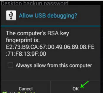
Figure 3. “Allow USB debugging?” message.
The device name should appear under Connected Devices in the wizard (see Figure 4). Highlight the device name and click OK. The task will be executed, the APK (Android PacKage) will be installed in your device, and the camera server will be launched.
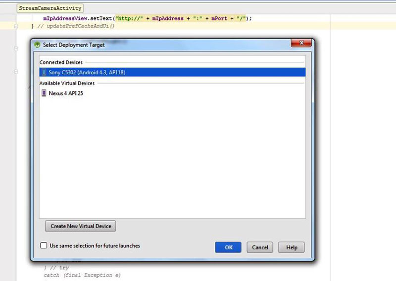
Figure 4. The “Select Deployment Target” wizard.
In Mi type phones, you’ll get an “Install via USB” message on the screen. Click install. You’ll now get another message; click Accept to install the APK in the device. After successful installation, you’ll find the NUTS&VOLTS icon in the device display. By tapping the icon, you can run the camera server.
Testing the Project
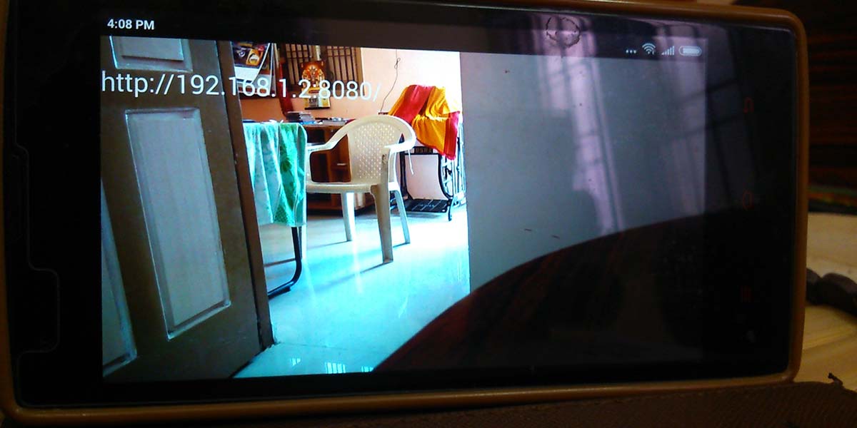
After tapping the NUTS&VOLTS icon, the camera server app will be running, and you’ll see the images on the screen displayed by the camera; the camera URL will appear in the top left corner (Figure 5). Except for http://, the remaining digits are fed as the camera URL to the ESP8266 webserver.
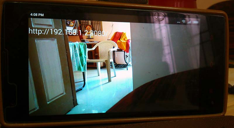
Figure 5. Image on the mobile phone showing the camera server app running with the URL displayed at the top left.
Open the HyperTerminal on the PC with the baud rate at 115200. In the HyperTerminal, power on the unit and bring the ESP8266 into setup mode by holding the S3 button. Do a reset using the Reset button and release the S3 button. The board will now go into setup mode and you’ll get a prompt for entering the SSID password and camera URL. Separate the SSID password and URL using commas and press the Enter button (Figure 6). The SSID password and camera URL will be stored in EEPROM.
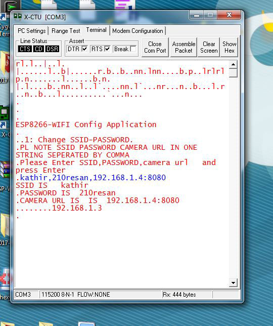
Figure 6. Screenshot of the SSID, password, and camera URL entry from HyperTerminal.
For subsequent use, the Wi-Fi setting is not required, and you don’t need to use switch S3. When Wi-Fi is connected, the IP address will be shown in the LCD display.
Launch the browser with the IP address. You’ll get a web page showing the live camera activity (Figure 7). The buttons marked as LED ON and LED OFF are used for switching the LED which is connected to GPIO pin 4. Appliances like fan motors can be switched on-off with a suitable relay driver circuit using optocouplers in GPIO pin 4. The status of GPIO12 and the temperature reading are displayed using AJAX scripts without refreshing the entire webpage.
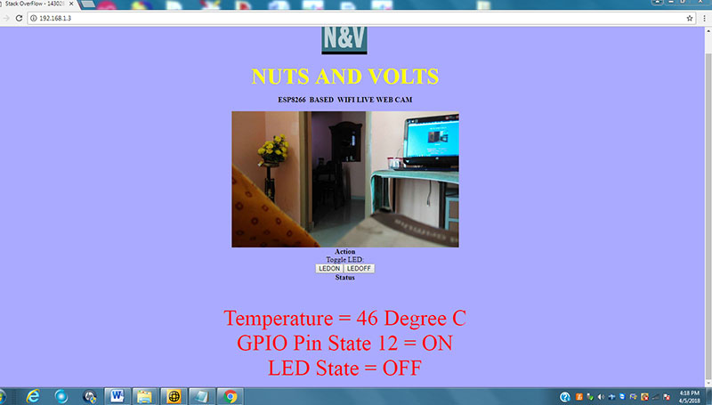
Figure 7. Web page.
Sometimes refreshing temperature data using AJAX scripts can cause stack overflows in the ESP module. If this happens, you’ll have to increase the refreshing time by changing 2000 to 3000 in the following line in the ESP-WIFI-LCD4.ino file:
s4 += “ setInterval(function() {“;
// Do something every 1 seconds
s4 += “ refreshDiv(‘div2’,’Status.cgi’,’/home’);”;
s4 += “ }, 2000);”;
Final Thoughts
This was a simple and fun project with lots of flexibility. For example, the camera could be implemented for remote visual control utilizing buttons on the web page.
For simplicity, we used LEDs for control. You could also control industrial equipment with heavy-duty switching contactors using optocouplers in the GPIO pins. We just used a single camera here, but multiple cameras can be used on different Android phones by linking them to the ESP module through software.
Use a stepper motor to rotate the camera in all directions using suitable hardware and software linking to the ESP module. You could also use a separate pushbutton for entering the camera URL. Due to the limited number of GPIO pins, we used the single pushbutton S3 for all.
Hopefully, these ideas will inspire you to give the ESP8266 a try. NV
Downloads
What’s in the zip?
Code Files