After successfully completing two different model digital clocks with large LCD displays and using the ESP32, I wanted to build a smaller version. Check out my previous articles at https://www.nutsvolts.com/magazine/article/build-an-internet-digital-clock and https://www.nutsvolts.com/magazine/article/an-esp32-teensy-3.5-super-clock. Reading these will help with understanding some of the details of this article.
I have a bag full of four-digit yellow .56 inch seven-segment LED displays I purchased from Electronic Goldmine that have individual pins for each segment of each digit. This makes them difficult to implement as a scanned display because of the large number of connections that must be made. However, a printed circuit board (PCB) solves this problem.
The ESP32 microcontroller and its various peripherals can all fit on a 3.5 x 2.8 inch PCB. This is the default miniboard size available from ExpressPCB, where I have all my PCBs made. The two four-digit LED displays need to be mounted one above the other to fit on the board.
Initially, I thought I would use just the ESP32 microcontroller and whatever was needed to drive the seven-segment displays along with the DS3231 Real Time Clock (RTC). It doesn’t take much to add the BME 280 temperature and humidity circuit, so that was easily included.
The circuit was put together on a breadboard and everything worked nicely. I printed a small box to house things with my 3D printer and mounted the PCB. With just the seven-segment displays showing and a single LED to signify an Internet connection, I thought it looked a little bare. More is better, right?
The top of the box would fit an LCD display of four lines of 20 characters, and it could display weather or other information which the ESP32 can retrieve from the Internet. At about the same time, I started thinking about the fact that the ESP32 has two cores; meaning it actually has two separate microcontrollers available.
When you program the ESP32 with the Arduino IDE (integrated development environment), the program is loaded into core 1 by default and the second core (core 0) is supposedly not used. (More on this later.) What a waste, I thought. Why not use one core to do the scanning of the LED displays (at least 30 times a second) and the other core could be used for everything else: reading the RTC; reading the BME280; and going out to the Internet for information to display on the four-line LCD.
It was at this point that things started to go wrong. The code for scanning the LED displays was left on core 1 and was the first portion of the code I wrote. This just means that it was placed in the normal void loop() structure of an Arduino program. The portion of the program running on core 0 takes some extra code to set up.
A task handle is defined first. This is placed after the #include statements and before the setup() section:
TaskHandle_t Task1;
In setup(), you create a task assigned to a specific core with the following function call:
xTaskCreatePinnedToCore(
Task1code, // Function name to implement the task
"Task1", // Name of the task
2000, // Stack size in words
NULL, // Task input parameter
1, // Priority of the task
&Task1, // Task handle
0); // Core where the task should run
Lastly, the function to implement the task is created. In our case, it was called Task1code. An important thing to remember is that the function Task1code must never end or attempt a return. This is the easiest way to crash the ESP32. To insure this doesn’t happen, all the code is placed inside a while(true) loop. This then acts just like the loop() in a normal Arduino program.
The code running on core 0 included reading the RTC, reading the BME280, and getting time and weather from the Internet, which was then displayed on the four-line LCD. All three of the peripherals -- RTC, BME280, and LCD -- are driven from the I2C interface. The SDA line is on pin 21 of the ESP32 and the SCL line is on pin 22. The RTC and BME280 worked flawlessly, but the LCD gave me fits for days.
The first time the LCD was written to it was usually fine. The second time it wrote to the LCD a minute later, it had missing or incorrect letters. After a few more writes, it just did nothing. An Internet search turned up that there were issues with the implementation of the I2C interface on the ESP32. A patch was found (which I did), and it seemed to improve things, but the display was just not stable.
I added filtering to the 3.3 volt line. Then, pullups to the I2C lines were tried, which made things worse. My assumption was that there was a problem with the I2C interface, as this was the interface to the LCD display.
Finally, after several days of frustration, I came across an online mention that core 0 has some limitations that really weren’t pertinent to my situation, but it got me thinking. I had the bulk of the program running on core 0. Why not try simplifying its task load by just putting the LED scan work on that core.
So, I switched the software the two cores were running and that basically solved the problem! I later realized that core 0 is also used by the Wi-Fi and Bluetooth radio. Here’s function Task1code() -- my total code for core 0:
void Task1code( void * parameter)
{
// Task here must never end or return
while(true)
{
// Core 0 just scans LEDs
switch (last_sec)
{
case 1: case 2: case 3: case 4: case 5: date_one_scan(); break;
case 31: case 32: case 33: case 34: case 35: temp_hum_one_scan();
break;
default: time_one_scan();
}
}
}
Core 0 checks what second it is and if it’s one to five, it displays the date on the LED displays. If the second is 31 to 35, it displays the temperature and humidity from the BME280 circuit. Otherwise, it displays the time.
The three functions -- time_one_scan(), date_one_scan(), and temp_hum_one_scan() -- are all very simple. For each digit on the LED display, it does something like the following which is for the seconds units display:
digitalWrite(EN, HIGH); // disable outputs
set_segs(num[last_sec % 10]);
set_digit(1);
digitalWrite(EN, LOW); // enable outputs
delayMicroseconds(del);
The output is disabled before setting the seven segments and the correct digit. Then, the output is enabled for a given number of microseconds set by the variable del. The longest I found was 2,200 microseconds before flicker became noticeable. I thought the display was a bit dim in a lighted room, but in a darkened room it’s almost too bright. I settled on 2,000 microseconds. Different displays may need adjustment here.
Ghosting can be a problem when scanning LED displays, and the disable-enable pair helps reduce this. The EN (pin 16 on the ESP32) is connected to the enable on the 74HCT138 3-to-8 decoder. The use of this decoder also reduces the number of output pins needed on the ESP32.
In addition, when a digit is not used (like those before and after the seconds display), this digit is completely not set instead of setting all the segments off.
What core 0 does is pretty simple. It’s basically just doing lots of digitalWrite() to output pins. Perhaps more importantly, it’s not utilizing any of the many libraries core 1 is using like I2C, Wire, or Liquid_Crystal_I2C, etc. I’m left with the impression that the core 0 load should be the lesser of the two.
Unfortunately, many of the examples I found online about how to set up the two cores were very simplistic; like each core flashing an LED at a different rate. There is also a caveat here -- as noted above -- the Wi-Fi radio only runs on core 0. So, while all our instructions that call for Wi-Fi use occur from core 1, the Wi-Fi radio itself is operated by core 0.
This can still lead to short delays during the scanning of the LED displays. I note just the smallest amount of flicker from time to time.
Hardware
Figure 1 shows the entire schematic of this ESP digital clock.
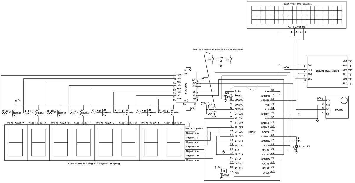
Figure 1. Schematic of the ESP32 digital clock.
The most complex part of the circuit is the seven-segment LED displays and their drivers. Each common anode digit is powered through a 2N3906 PNP transistor which has its base driven by the 74HTC138 decoder. The ESP32 outputs a three-bit address plus an enable to the 74HTC138 to power each digit one at a time. The seven-segment lines for all eight digits are tied together on the PCB and then each segment is connected to an output pin on the ESP32.
The patterns for each seven-segment numeral, along with the letters F and H (Fahrenheit and Humidity), are stored in single bytes. The seven-segment pattern for a byte is DP, A, B, C, D, E, F, G, going from the high bit to the low bit.
Since a segment is activated with a 0, or ground state, the pattern for the number one is 11001111. Segments B and C have a zero in their position; these two segments create the number one on a seven-segment display.
The correct pattern is output to the seven segments and then a single digit is enabled by the 74HCT138, enabling one of the PNP transistors, followed by another seven segments, and then the next digit enabled. This runs through all eight digits and it must happen in less than 33 milliseconds to give a flicker-free 30 frames a second.
Pin 17 is used to light up a single LED to signify there is an Internet connection. Three input pins -- 34, 35, and 39 -- are connected to switches on the back panel and used to select different modes of operation. The ESP32 doesn’t have built-in input pullup resistors to the 3.3 volt supply, so these needed to be added on the PCB.
The 74HTC138 circuit is an SMT package, with its pins on 0.05 inch centers. This can be a challenge to solder onto the PCB, but with care and patience it can be done with a fine-tip soldering iron.
Check your soldering on this device if your display does strange things with the digits. Pins 21 and 22 implement the I2C bus and these are connected to the RTC board, the BME280 board, and the LCD. These boards also need a five volt and ground connection.
For the five volt power supply, I used a wall wart type of five volts/two amps. It connects to a mating power jack on the back panel which has wires connecting it directly to the PCB. This power supply was overkill as the circuit draws about 310 milliamps maximum.
The RTC board was mounted on the back of the PCB as shown in Figure 2. With the seven-segment LED displays facing forward, the backup battery on the board can be accessed without removing the entire PCB.
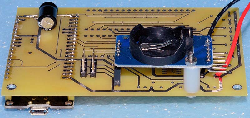
Figure 2. Mounting the RTC board on a prototype PCB.
Header pins were soldered into the four-pin pads opposite the provided right angle pins on the RTC. This header then plugs into a four-pin header socket on the back of the PCB. Notice also that header pins for the BME280 and LCD were soldered onto the back of the PCB for easy access.
A 2-56 machine screw with spacer was used through one of the small holes in the RTC board. A hole on the PCB is provided for this and gives the RTC board stability. Although useful, a backup CR2025 battery is not really necessary. When the circuit is plugged in without the battery, the display shows garbage numbers, but within a minute the time is read from the Internet and the RTC reset to the correct time.
This is an advantage of this design. The RTC never needs to be set, eliminating the annoying reprogramming for Daylight Savings Time changes. The trade-off is that the clock must be within range of your Wi-Fi.
Figure 3 shows the completed PCB. Wires from the PCB connect to the BME280 and blue LED at the right, and to the input switches and power jack on the rear panel.
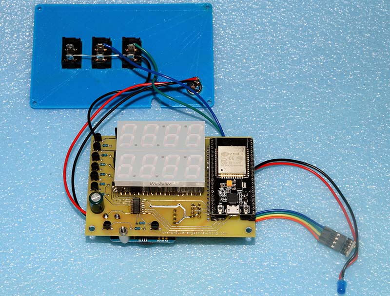
Figure 3. Completed prototype PCB with back panel switches and power jack.
The assembled PCB is shown installed in the project box in Figure 4, with the LCD display mounted on the top. Note the added filter capacitor on the 3.3 volt line and pullup resistors in the upper left that were added to the prototype PCB. Changes were made to include these in the PCB layout supplied in the download area.
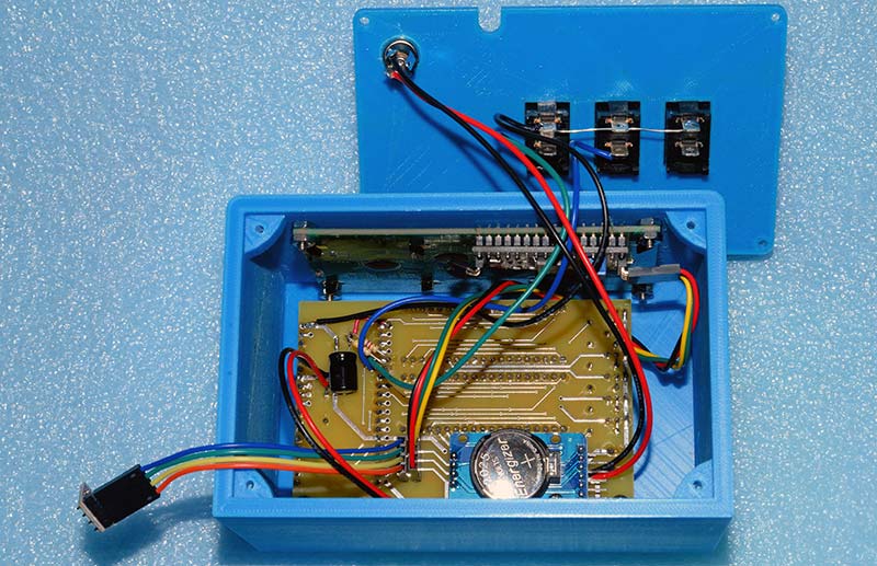
Figure 4. Assembled PCB in project box.
A custom box created on a 3D printer is a great addition to a project like this. When designing the box, you have complete control over the size and -- more importantly -- the placement of openings for the displays and their mounting screws. The rear panel has holes just the right size for the snap-in switches and power jack, and a cutout for the wires for the BME280 board.
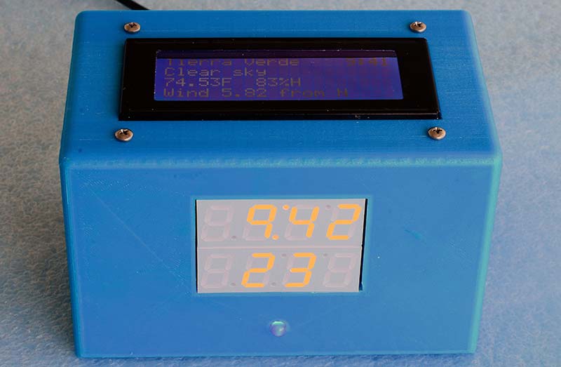
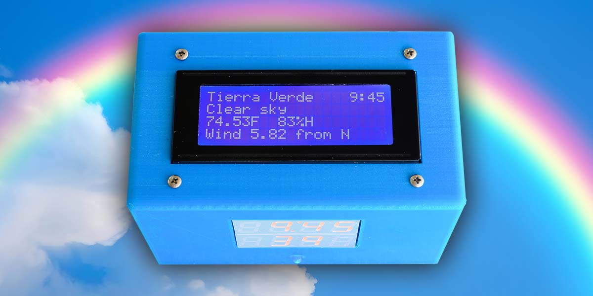
Figure 5. Front panel of the digital clock.
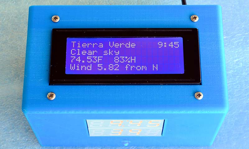
Figure 6. LCD readout on the top of the project box.
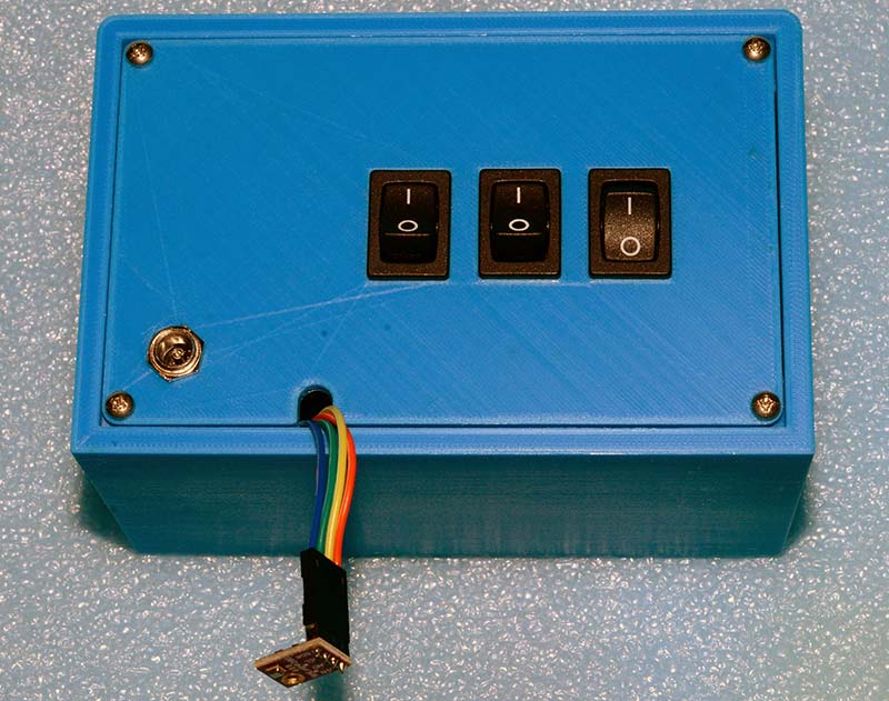
Figure 7. The rear panel.
The Sketchup files and object files for this project box are included with the article downloads. The object files scan be used with the free Ultimaker Cura program to produce g-code files to run on other 3D printers.
There are a confusing number of ESP32 board variations from different manufacturers including differences in the number of pins and the pin spacing. This project uses ESP32 boards with 38 pins and is programmed by selecting NodeMCU-32S as the board in the Arduino IDE. The 38-pin models also come with 0.9 inch and 1.0 inch spacing across the board.
For example, the HiLetgo ESP-WROOM-32 ESP32 ESP-32S development board (which can be found on Amazon) has 38 pins and 0.9 pin spacing. On this model, you must press the boot switch to start your program upload. The AZDelivery ESP32 Nodemcu CP2102 Module WLAN Wi-Fi development board (also available from Amazon) has 38 pins but 1.0 inch horizontal spacing. You don’t have to press the boot button to start uploading your program on this model.
Both these ESP32 boards have identical pinouts. To simplify things, the PCB layout (available with the downloads) has a double row of connected pins on the left side, so either 0.9 or 1.0 inch spacing ESP32 boards can be used.
Figure 8 shows three different ESP32 modules, all using the ESP-WROOM-32 module. First on the left is the ESP32 DevKitC, supplied by Elector, who also provided The Official ESP32 Book, by Dogan and Ahmet Ibrahim. This book contains a group of fairly simple exercises for using the ESP32. Next is the AZDelivery ESP32 Nodemcu CP2102 module, and on the right is the HiLetgo ESP-WROOM-32 ESP32 ESP-32S development board.
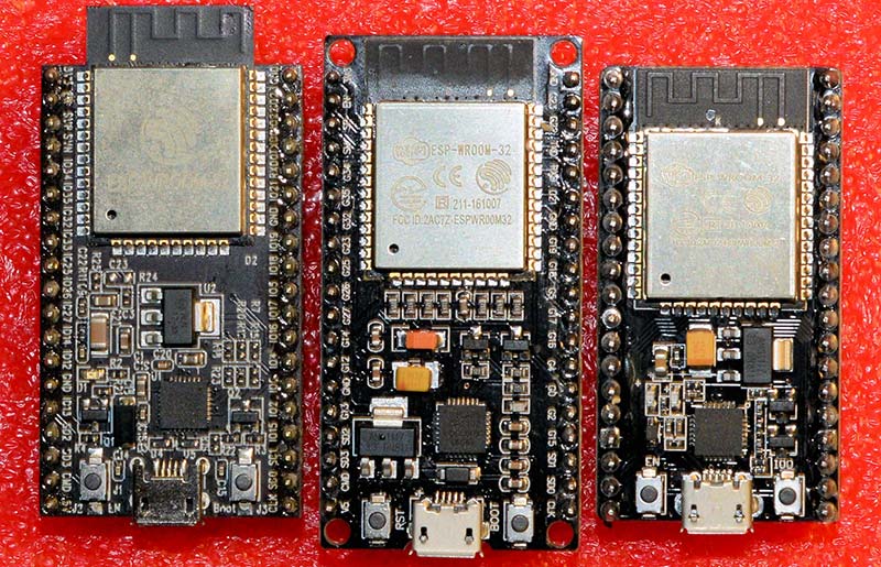
Figure 8. Three different ESP32 modules.
All three of these ESP32 modules can be used on this project and have identical pinouts. Some features vary (caveat emptor); for example, the HiLetgo dev board has a bright red LED indicating power on and a blue LED connected to pin 2. Figure 9 is a pinout diagram for this module.
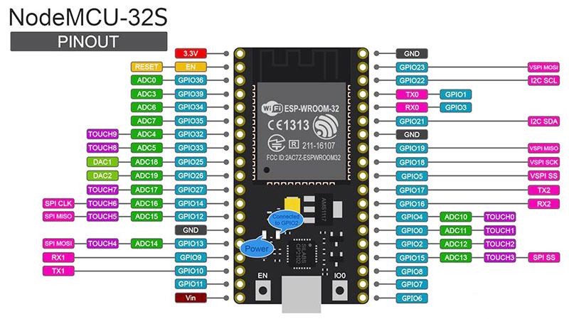
Figure 9. The ESP32 38-pin model.
Here are some of my rules of thumb for using the ESP32. Pins are often labeled with a GPIO acronym like GPIO21, meaning General-Purpose Input Output.
- Five volts only into the Vin pin.
- Do not use pins 6, 7, 8, 9, 10, or 11. These are connected to the integrated SPI Flash and unless you really know what you’re doing, leave them alone.
- I try not to use pin 12. If you have the ESP32 powered in a circuit and pin 12 is held high, the ESP32 will not upload a program.
- Pins 34, 35, 36, and 39 are input only pins. In addition, they don’t have internal pullup resistors. These must be provided by the external circuit. I used 4.7K resistors connected to the 3.3 volt pin.
- Pins 1 and 3 are TX0 and RX0 and are used by the serial monitor. I avoid using them for anything else or you probably won’t be able to use the serial monitor.
- Pins 21 and 22 are the default I2C pins SDA and SCL.
- Pins 5, 18, 19, and 23 are the default SPI pins SS, SCLK, MISO, and MOSI. See the SD_Test.ino example. This can be found in the ESP32 package usually on your hard drive at C:\Users\Your_User_Name\AppData\Local\Arduino15\packages\esp32\hardware\esp32\1.0.0\libraries\SD\examples\SD_Test. Examples under SD in the Arduino IDE will not work since different libraries are used.
Software
You’ll need to have the ESP32 board package installed in your Arduino IDE to be able to compile and upload the program provided in the downloads. Here’s a link to the best set of instructions I have found for installation: https://randomnerdtutorials.com/installing-the-esp32-board-in-arduino-ide-windows-instructions/. After installation, you’ll need to select NodeMCU-32S as your ESP32 board.
The flowchart for the core 0 microcontroller (Figure 10) is quite simple and the entire code was discussed previously.
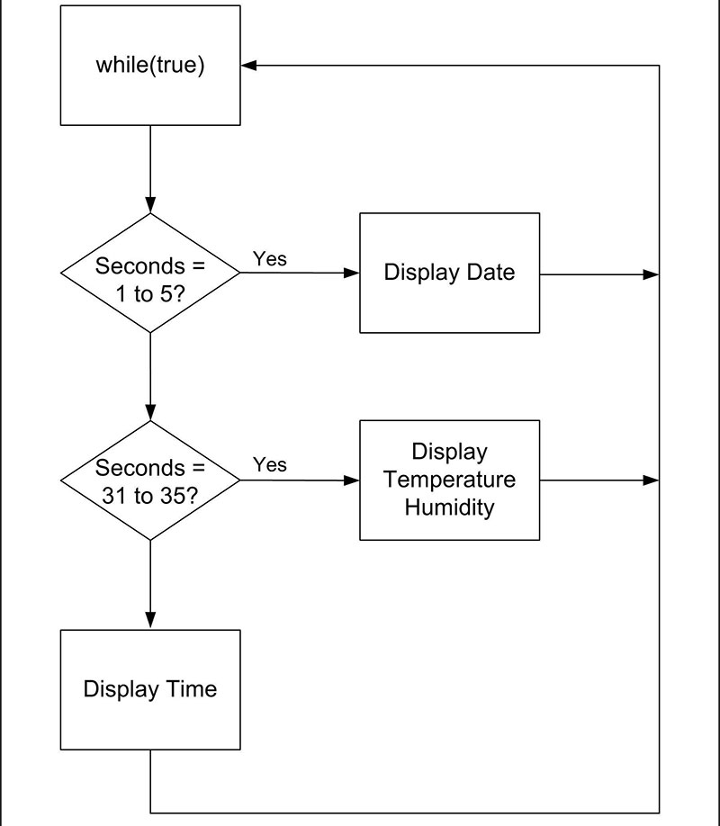
Figure 10. Core 0 flowchart.
The flowchart for the program running on core 1 is more involved (Figure 11).
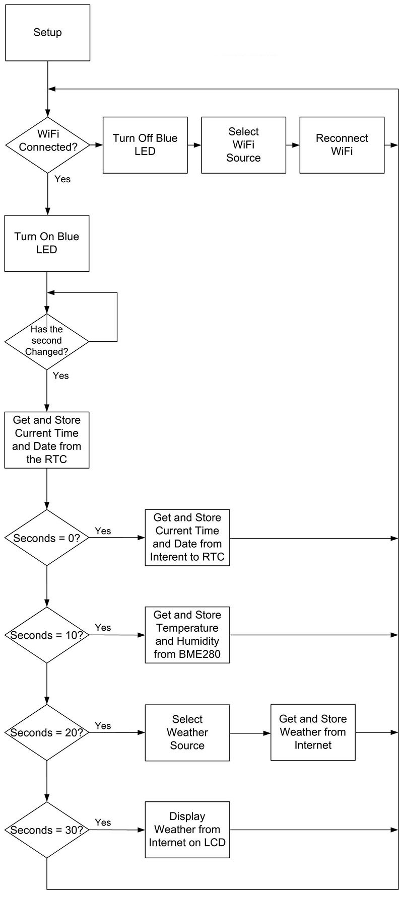
Figure 11. Core 1 flowchart.
First, it connects to the Internet via Wi-Fi. If this connection is lost, it simply retries to connect. Two different SSID names and passwords are stored in the program. Which one is chosen depends on the setting of one of the switches on the back panel. In this way, the digital clock can be transported between two locations with different Wi-Fi names and passwords without having to reprogram the ESP32.
The program then enters a loop that checks to see if the second value has changed from the RTC. If it has, it reads the time and date and stores these values in variables.
Four if statements are then checked. At zero seconds, the program reads the time and date from a National Time Protocol (NTP) server, then overwrites the time in the RTC with these values. At 10 seconds, the local BME280 is read and the temperature and humidity is stored. At 20 seconds, the weather data is gathered from api.openweathermap.org and the few items we wish to display are saved after parsing them from the JSON output (JavaScript Object Notation is a lightweight data-interchange format).
At 30 seconds, we write our weather data to the LCD display. Note that we have given api.openweathermap.org 10 seconds to respond to our weather data request. Two weather locations are stored in the program and again a switch on the back panel determines which one is used.
With these two switches on the back panel, a college student, for example, can switch between his home and school Wi-Fi and weather information by simply changing the switches on the back panel.
Notice that core 1 just reads and stores time, date, temperature, and humidity. Core 0 will take care of reading the stored values and displaying them on the seven-segment LED. Core 1 reads and displays the weather information, as that is written to the LCD and does not interfere with the seven-segment displays.
The complete program is available with the downloads. NV
Parts List
| ESP32 38-pin NodeMCU-32S |
eBay, Amazon |
| 40-pin IC socket, cut lengthwise for correct ESP32 spacing |
eBay, Amazon |
| Yellow four-digit seven-segment LED displays (2) |
Electronic Goldmine |
| DS3231 RTC module |
eBay, Amazon |
| BME280 temperature/humidity module |
eBay, Amazon |
| LCD display, four-line, 20-character, with I2C interface |
eBay, Amazon |
| 74HCT138, SMT, SOIC, 0.05 inch pitch |
eBay, Amazon |
| 2N3906 PNP transistors (8) |
eBay, Amazon |
| 1K 1/8 watt resistors (9) |
eBay, Amazon |
| 1,000 µF, 6.3 volt electrolytic capacitors (2) |
eBay, Amazon |
| Blue LED |
eBay, Amazon |
| Header pins |
eBay, Amazon |
| Header pin sockets |
eBay, Amazon |
| Header pin jumpers |
eBay, Amazon |
| SPST switches (2) |
eBay, Amazon |
| Project box, 3D printed |
Files with downloads |
| Five volt, minimum one amp wall wart type power supply |
eBay, Amazon |
| Mating power jack for power supply |
eBay, Amazon |
| Various screws, nuts, standoffs, solder, hookup wire, shrink tubing |
Home Depot, Lowes |
Downloads
What’s in the zip?
Code Files
PCB Files
3D Printed Case File