Several months ago, I bought a vintage Allied Radio Knight-Kit 12-in-1 Electronic Lab on eBay. It used a 12K5 low voltage vacuum tube instead of transistors, as shown in Figure 1. As I was wiring up my "wireless AM broadcaster" project, it hit me. Why not combine the past with the present? Put an Arduino with a vacuum tube shield — a Retro-Shield!
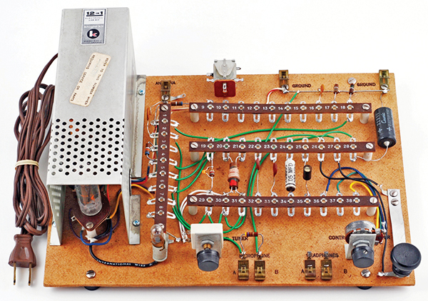
FIGURE 1. The 12-in-1 Knight-Kit uses point-to-point soldered wires to build the projects.
The Vision
Actually, this idea didn’t just come out of the blue. I had been puttering around with an Arduino Uno from RadioShack, and since the 12K5 vacuum tube only needed 12 volts to operate, I made the connection.
In my head, I could see the end result. It would be a stack of shields with the vacuum tube on the top board, glowing in the dark. I wasn’t sure yet what it was going to do, but I knew it would be cool.
Fast Forward
Before I get into the details, I want to say how much fun this project turned out to be. First, I successfully dissected a vacuum tube and learned how it worked. Secondly, I had fun broadcasting silly messages around the house, along with Christmas music that at the time made our holiday very special. The talking clock drove my wife nuts, but I loved it. And finally, I built my first Arduino shield and managed to get it working just the way I wanted. What more could I ask for?
An mp3 sample of my broadcasts can be found at the article link. The first portion of the sample is a sentence generated by the talking clock; the second section is from a music player; and the last part is my voice, using a microphone. The sequence is repeated twice. I think you’ll enjoy it.
Back to Business
Now, back to the project. How could I possibly wed the broadcaster to an Arduino? I remembered some ads for sound-generating shields that produced voices and weird sounds for robots and talking clocks. A GinSing Sound Synthesizer shield looked interesting, but the demos sounded a little too unnatural for me.
The SpikenzieLabs VoiceShield had a different approach. It simply stored digitized audio, then played it back when triggered by an Arduino. The VoiceShield’s memory could hold four minutes of audio. One application for it was a talking clock. You could load it with 80 prerecorded words, such as: the, time, is, now, one, o’clock. Or, you could put in any audio you wanted.
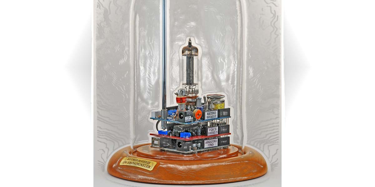
So, at last I had a vision of the final configuration; take a look at Figure 2.
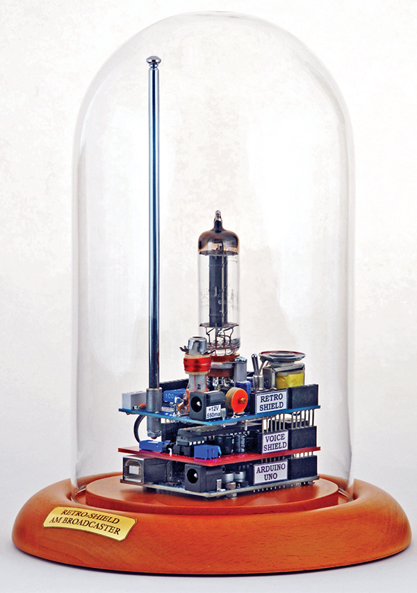
FIGURE 2. A glass dome is great for display and the inkjet printed label gives it a nice title.
It would be three boards: an Arduino on the bottom, a VoiceShield in the middle, and the broadcaster on top. I figured that once it was finished, I would program the Arduino to announce the exact time — once every five minutes — to all the radios throughout the house. I was sure my wife would love it.
12K5 Low Voltage Vacuum Tube
Most vacuum tubes require 100-300 VDC to operate, which sometimes presents a hazard for experimenters — young and old. If you aren’t careful, you could get a nasty shock if a finger brushed against a 300 volt terminal.
The 12K5 tube used in the Knight-Kit was different. It only required 12 volts for the filament, grids, and plate. The schematic in Figure 3 shows how the elements of the tube are connected in the Retro-Shield. Please note the element names: filament, cathode, grid 1, etc.

FIGURE 3. The Retro-Shield can accept audio inputs from three different sources.
Back in the 1950s, a company named Tung-Sol developed a line of “Space Charge” tubes just for car radios. They only needed the low voltage from the battery to operate — no high voltage. The tubes were only sold for a few years, however, because transistors were rapidly improving, and soon car radios were completely transistorized.
In case you’re not familiar with the parts of a tube, please take a look at Figures 4-6.
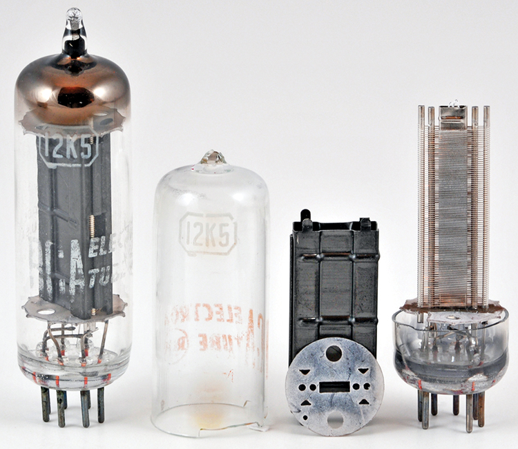
FIGURE 4. A circular nichrome hot-wire was used to fracture the glass envelope near the base.
In Figure 5, the cathode is the silvery hollow tube in the middle, with a folded alumina coated tungsten filament tucked inside, but peeking out the to.

FIGURE 5. The inner grid (grid1) wires are hard to see because they are obscured by grid 2.
The two grids are the fine wires which are spiral-wrapped around the shiny support rods and nested inside of each other. In Figure 4, the plate is the hollow black ribbed rectangular structure and the round piece in front of it is a piece of thin mica — an insulator. During assembly, the plate is carefully slipped down over the grids and held in place by mica disks at the top and bottom. The whole thing is an intricate structure all nested inside of each other, but not touching.
Each of the elements is spot-welded to the pins in the glass base, and a glass envelope is slipped down from the top. The envelope is sealed to the base with a torch, and then the air is sucked out through a small glass tube at the top. Another torch melts the small tube closed, sealing the vacuum inside. You can see the melted tip in the upper left of Figure 4.
In operation, 12 volts is applied to the filament and heats it up to over 1,000 deg C, as seen in Figure 6.
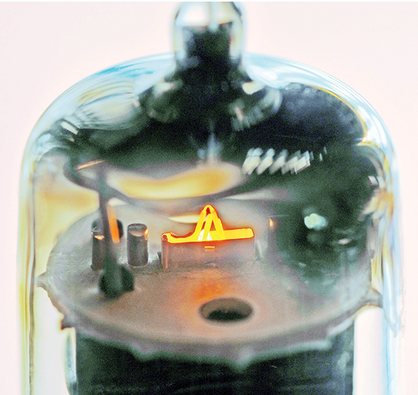
FIGURE 6. The glass envelope of the tube can be over 100°C, so be careful.
The hot filament, in turn, heats the oxide-coated cathode which boils off a cloud of negative electrons — called the space charge. Grid 1 — which is hooked to +12 volts — is located very near to the space charge region and attracts most of the electrons to it. However, some do get through.
The accelerated electrons that get through grid 1 continue on through grid 2, and are attracted to the plate which is also hooked to +12V. The net result is that more electrons get to the plate as a result of grid 1 than if there was just the plate to attract them. Plus, these space charge tubes run the filament at a hotter temperature and have an increased cathode area in order to produce even more electrons than usual.
Now, if a small negative voltage (-4V) is applied to grid 2, it will repel the electrons back towards grid 1 and the cathode, shutting off some or all of the flow to the plate. In other words, a tiny change in the negative voltage on grid 2 makes a big change in the current flowing to the plate. This is how a tube can amplify a signal. However, in a practical amplifier circuit, additional components are needed to convert the plate current into a voltage and to bias the tube into the desired operating region.
The bottom line is the 12K5 is suitable for certain applications, but it’s not as powerful as tubes that use high voltage. In the Retro-Shield, the 12K5 serves a dual purpose. L1, C11, C12, and R6 form a radio frequency (RF) oscillator tuned to the AM radio band. In addition, the audio frequency signal coming into T1 modulates the plate voltage, causing the amplitude of the RF output to go up and down with the audio.
Searching for Parts
Before getting too excited about this project, I needed to find sources for the critical parts. The Knight-Kit was over 50 years old, and I wondered if the 12K5 and oscillator coil (L1) were still available. A good friend turned me on to a company called Antique Radio Electronics. Zowie! It was tube heaven! They had all kinds of cool things. A 12K5 was only $3.95 and the coil was $8.95. I’m not sure how many of these items they keep in stock, so you might make sure they are available before you get started. I noticed that the 12K5 also showed up on eBay and MDB Ventures.
Improving Output Power
e only hitch with the Knight-Kit broadcaster was range. It didn’t transmit very far. Of course, the little telescoping antenna was woefully short. I built a proper loading coil but it was quite large and not practical, so I gave up on that approach. Boosting the current through grid 1 to 56 mA raised the plate current to 4.1 mA and improved the RF output. I found that a good earth ground also helped reduce the 60 Hz pickup and added a ground plane. The ground (green) wire is shown in Figures 7 and 8.
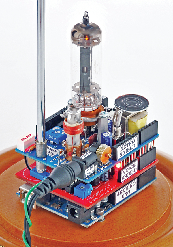
FIGURE 7. The speaker is mounted on top of T1 with foam tape.
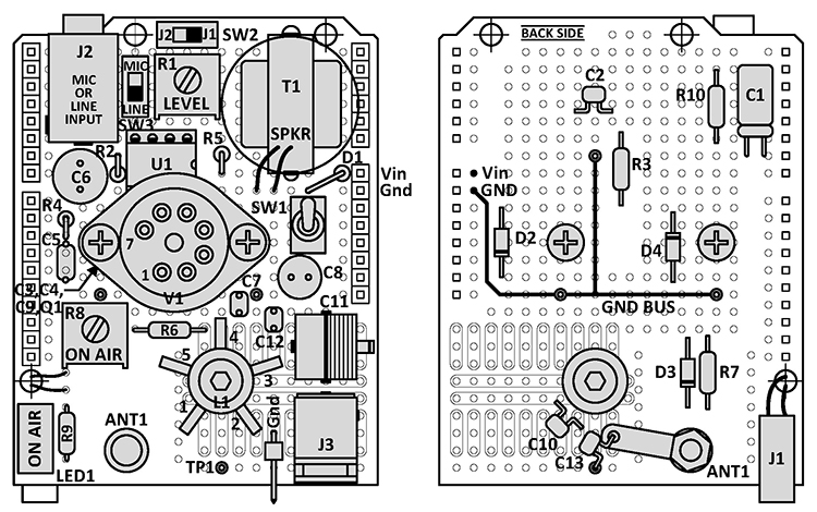
FIGURE 8. The ground pin, next to J3, connects the board to Earth ground.
Finally, I changed the output capacitor from the original 100 pF to 0.01 µF, which raised the output considerably. The improved signal was strong enough to reach all the radios in the house, but only if they had decent receiving antennas. I was unable to get an output power measurement that I believed, but I compared its output to a 100 mW Ramsey AM Broadcaster Kit and both seemed about the same.
FCC (Federal Communications Commission) Part 15 specifies a limit of 200 feet for an unlicensed AM transmitter. I also saw a limit of 100 mW in the FCC OET Bulletin No. 63. Either way, the range of the Retro-Shield should not interfere with your neighbor’s radios. If you think there is a problem, simply reduce the value of C10.
Now, a word about AM radios. Most home stereos definitely need an external AM antenna to receive signals from the Retro-Shield. Some stereos come with a goofy little AM loop antenna, but it’s better than nothing. Failing that, a 10’ hank of wire would probably be enough. I used a small transistor radio to check the reception throughout the house, and the signal was pretty good everywhere.
Building the Retro-Shield
Of course, you don’t have to put together a stack of three boards as I did; you can build the broadcaster as a stand-alone unit. I sometimes use it to send iTunes from my PC to the radio in the garage. Next Halloween, I plan to pipe some scary music to a portable radio outside.
This project is not a slam dunk. You have to use your imagination and expertise to build and test the system. The Retro-Shield has both high (1 MHz) and low frequency (audio) signals running around. Try to keep the RF signals as isolated as possible. The LM386 IC had some pickup problems at first, but a friend suggested adding C2 and it solved the problem.
I selected the Arduino proto shield for the top broadcaster board, just to keep it in the Arduino family. A piece of perf board would be fine too, since only two pins (Vin and GND) are needed to carry the 12 volt power down to the shields below. A ground plane perf board would probably be even better. J1 routes the audio up from the VoiceShield.
The proto shield board has a small number of tiny traces that carry signals and power to various places. All these traces should be cut so they do not interfere with the broadcaster circuitry. The layout is shown in Figure 9.
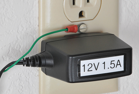
FIGURE 9. The ground pin next to J3 connects the board to earth ground.
I didn’t show individual connections because it would be much too busy. Just use point-to-point wiring; the components are grouped. The parts on the bottom of the board are shown in their approximate positions. Some holes need to be enlarged for V1, T1, L1, J1, and ANT1. Extra holes are also needed for some leads. If you decide to include C11a for fine-tuning, solder it in as a piggyback on top of C11.
Final Testing
First of all, L1 is shipped with the ferrite tuning slug at the very bottom. It needs to be screwed upward until it is roughly centered in the coil. Be sure to use the 0.100” nylon hex tool (Tool2). Allen wrenches are not the right size and can crack or chip the slug. Later on, the slug can be used to fine-tune the RF output frequency.
Set SW3 at “line,” SW2 at “J2,” level pot (R1) to minimum, and the On Air pot (R8) to max. Next, position an AM radio within a few feet of the Retro-Shield and set it at 1,200 kHz or a quiet spot near there. Connect the 12 VDC adapter to J3 and turn on the power switch (SW1). After several seconds, you should see the filament start to glow like in Figure 7.
Please note that the glass envelope gets pretty toasty — 100 deg C — so don’t touch it until it cools off. Now, you are ready to get serious.
To test the broadcaster, you’ll need a source of music — like an mp3 player or the headphone output of your computer or stereo. Plug the music source into J2. Slowly turn up the level pot until you hear the music coming out the tiny monitor speaker on the Retro-Shield. If you don’t hear anything, turn the level pot back to zero and check that music is truly coming through the cable.
Be careful not to overdrive the LM386 because it will draw several hundred milliamps and could go up in smoke. The trick is to turn the music up just loud enough to hear it, but without any distortion.
Be sure to use the LM386-4 which is rated for 5V to 18V. The gain of the LM386 is set at 200 for the microphone and attenuated by a factor of 48 for the line input.
Here’s a cool thing. It takes about 20 seconds for the 12K5 tube to warm up, so don’t expect the RF to immediately come blasting out like with a transistorized unit. Just be patient. After warmup, the On Air LED should light, indicating that RF is being generated. If you have a scope, clip it on the test point to see the RF waveform.
During development, I had trouble with the 2N7000 FET (Q1) in the RF monitor section. It kept blowing out. It might have been static electricity or too much RF. After I added a zener (D4), the problem went away. I suggest that you keep a spare FET on hand.
Next, adjust the tuning capacitor (C11) slowly until you hear the music coming out of the radio. The AM broadcast band is from 530 to 1,710 kHz. C11 tunes between 720 and 1,710 kHz. Turn the level pot up slowly until the music starts to overmodulate the RF, then back it down a bit. A scope is real handy for setting the modulation level.
Now that the broadcaster is working, let’s look at the VoiceShield.
Power and Programming Cables
First, let me give you a quick explanation about how to connect the USB and power cables.
Retro-Shield Only: Connect the 12 VDC at 1.5A AC adapter to J3. The 12K5 has a surge current of about two amps, which drops to under 500 mA after warmup.
Arduino Uno and VoiceShield: Connect a USB cable to the Uno for programming and power.
Stack of Three Boards: Connect a USB to the Uno for programming. Connect the AC adapter to the Retro-Shield to provide power to all three boards, down through the Vin pins.
The VoiceShield
On the VoiceShield board, you’ll need to solder a two-pin right angle header to the speaker out terminals, which mates with J1. The SpikenzieLabs website (www.spikenzielabs.com) has a tutorial on how to download and use the software for the Arduino and VoiceShield. I have embellished on the tutorial and my write-up is included in the sidebar below. Using the VoiceShield really isn’t all that complicated, but there is a learning curve.
After I got the VoiceShield working, I made up an mp3 sample of the talking clock and other broadcasts, as mentioned at the beginning of this article. For the sample, the broadcaster was located in the house and an AM radio was in the garage. It picked up the transmitted signal on 1,480 MHz; the headphone output was stored in an mp3 file, which is what you will hear on the link. Click to hear audio sample.
Final Thoughts
As for the future, the broadcaster board could be housed in a nice metal case for shielding, and the controls could be changed to ones that have knobs. Perhaps the tube could even be replaced with a transistorized circuit so it doesn’t draw so much power. I would sure hate to see the tube go, however, since it’s so quintessentially “Retro.” NV
PARTS LIST
| ITEM |
DESCRIPTION |
DIGI-KEY (unless otherwise noted) |
| C1 |
10 µF, 25V, non-polarized |
P1176-ND |
| C2,7,10 |
0.01 µF, 200V |
399-4261-ND |
| C3 |
10 µF, 25V |
P5148-ND |
| C5 |
0.047 µF, 50V |
P5148-ND |
| C6 |
220 µF, 25V |
P5153-ND |
| C8 |
100 µF, 35V |
P5165-ND |
| C4,9 |
0.1 µF, 50V |
P4525-ND |
| C11 |
10-180 pF trimmer |
SG3019-ND |
| C11a (optional) |
2-15 pF fine-tune trimmer |
SG3025-ND |
| C12,13 |
10 pF, 200V |
399-4140-ND |
| R1 |
10K pot |
3386F-103LF-ND |
| R2,9 |
1K, 1/4W |
1.0KQBK-ND |
| R3 |
180 ohm, 1/4W |
180QBK-ND |
| R4 |
10 ohm, 1/4W |
10QBK-ND |
| R5 |
51 ohm, 1/4W |
51QBK-ND |
| R6 |
100K, 1/4W |
100KQBK-ND |
| R7 |
330K, 1/4W |
330KQBK-ND |
| R8 |
100K pot |
3386F-104LF-ND |
| R10 |
470K, 1/4W |
470KQBK-ND |
| D1 |
1N4004 diode |
1N4004FSCT-ND |
| D2 |
1N5818 Schottky diode |
1N5818FSCT-ND |
| D3 |
1N914 diode |
1N914BCT-ND |
| D4 |
1N5239, 9.1V zener |
1N5239BFSCT-ND |
| J1 |
Two pos, 0.1", housing |
609-1262-ND |
| PIN |
(2) 22-30 AWG female pins |
609-4453-1-ND |
| J2 |
3.5 mm mono audio jack |
609-1262-ND |
| J3 |
2.1 mm x 5.5 mm power jack |
CP-102A-ND |
| L1 |
Osc coil, P-C70-OSC |
Antique Electronic Supply |
| T1 |
Output xfmr, 1K to 8 ohms |
Mouser, 42TM013-RC |
| T1 alternate |
Output xfmr, 1K to 8 ohms |
RadioShack, 273-1380 |
| ANT1 |
Telescoping antenna |
Mouser, 43AR104 |
| NUT |
3 mm nut for antenna |
Hobby People, others |
| SW1 |
SPDT toggle |
EG2447-ND |
| SW2,3 |
SPDT slide |
450-1578-ND |
| LED1 |
LED bar, red |
516-1243-5-ND |
| SPKR |
20 mm dia, 8 ohm |
102-2502-ND |
| V1 |
12K5 vacuum tube |
Various Internet vendors |
| Q1 |
2N7000 FET |
2N7000FS-ND |
| U1 |
LM386N-4 pwr amp, 5V-18V |
LM386N-4/NOPB-ND |
| SOC1 |
Seven-pin tube socket, P-ST7-201MXB |
Antique Electronic Supply |
| SOC2 |
Four-pin DIP socket |
ED3308-ND |
| TOOL1 |
Var cap and pot adj tool, plastic |
SPTOOL-ND |
| TOOL2 |
Osc adj tool set, S-T9304 ($0.95) |
Antique Electronic Supply |
| SPACER |
Two 3/16 x 3/4 x 4-40 spacers |
1895K-ND |
| PWRSUP |
12 VDC @ 1.5A plug-in AC adapter |
Mouser 826-DA18-120US-M |
| PCB1 |
Arduino Uno |
Various vendors |
| PCB2 |
VoiceShield, SPL-005011 |
SpikenzieLabs |
| PCB3 |
Arduino proto shield |
Various vendors |
| DOME |
4.5" dia x 8" high dome and base |
Collecting Warehouse |
HOW TO PROGRAM THE VOICESHIELD
VoiceShield Basics
The ISD4003 voice chip on the SpikenzieLabs VoiceShield holds 240 seconds (four min) of sound, sampled at 8 kHz. The sounds enter the chip through the “audio in” jack as analog audio. Audio files cannot be directly downloaded to the chip. They must be “played” into the jack. The chip then samples and stores them.
Typically, the user specifies 80 three second slots, numbered 0 to 79. The Arduino can call the slots in any order. If a sound is longer than three seconds, it will extend into the next slot; therefore, the very next recorded sound needs to start at least two slots down (or whatever). You have to keep track of the length of your sounds so the correct slot(s) gets recorded and played back without any overlap. It’s tricky, but it works if you are patient.
If you have problems, there are two areas on the SpikenzieLabs website that may answer your questions:
1. VoiceShield, Software: Page 4 — Voice Shield FAQ and Troubleshooting
2. Forum, VoiceShield
Installation
1. The following installation was for a Windows XP machine. Other platforms are also supported by the vendor.
2. Download the Arduino IDE if not already loaded.
3. Go to the SpikenzieLabs/VoiceShield website and click on Software.
4. Download “Arduino VoiceShield Library” into the Arduino/libraries folder.
5. Create a VoiceShield folder and download “VSProgrammerLite.”
6. Locate the already downloaded SoundScore.txt file and download “SoundBytes” into the same folder.
7. Downloading “VoiceShield Programmer” is optional; the Lite version is fine.
Hookup
1. Connect a USB cable from your computer to the Arduino Uno.
2. Locate a 3.5 mm audio splitter so you can listen to the audio going into the VoiceShield.
3. Connect the input of the splitter to your computer’s headphone output.
4. Connect headphones to one output of the splitter.
5. Connect an audio cable from the other splitter output to the VoiceShield Audio In jack.
6. Set your computer’s audio output volume at a normal listening level.
Record 80 Prerecorded Words and Do a Playback
1. Open the Arduino IDE and load VS_Loader (in the Arduino/examples folder) into the Arduino Uno.
2. Run VS_Loader, then close the Arduino (because the port needs to be released).
3. Open VSProgrammerLite and select the port.
4. Press Program. Wait for 80 words to load. You should hear the words in the headphones as they are loading. If not, recheck the wiring.
5. Close VSProgrammerLite.
6. Move the headphone plug over to the VoiceShield Audio Out jack.
7. Open the Arduino again, load File/Examples/VoiceShield/BasicPhraseTalk, and run it.
8. You should hear a number of phrases being played from the VoiceShield memory, such as “How much is the train?”
Make Up Your Own Sentence and Play It Back
Load and run this simple sketch into the Arduino:
//Title: Play_VS_Slots
//
#include <VoiceShield.h>
VoiceShield vs(80); // create 80 slots
void setup()
{
}
void loop()
{
vs.ISDPLAY_to_EOM(56); // “Do” (play slot 56)
vs.ISDPLAY_to_EOM(68); // “You” (play slot 68)
vs.ISDPLAY_to_EOM(44); // “Want” (play slot 44)
vs.ISDPLAY_to_EOM(42); // “The” (play slot 42)
vs.ISDPLAY_to_EOM(50); // “Hot Dog” (play slot 50)
delay(2000); // delay 2 secs, then loop again
}
Now, you can write a simple program to say any of the 80 words listed in Table 1.
Audacity
I love Audacity. It’s a free piece of audio editing software that lets you see exactly what the audio waveform is doing. It has a very intuitive learning curve. It is simple to control the timing of clips by inserting “silence” or cutting out portions. You can amplify or reduce certain sections in order to match overall levels. In fact, I haven’t even scratched the surface regarding its capabilities, but I did have a lot of fun.
Recording Your Own Sounds, Music, or Voice
I had a number of problems putting in my own audio, but here’s what I found that worked.
1. Load your audio clips into Audacity — whether they are from a microphone, music player, or even Arduino-triggered words from the VoiceShield. Edit each clip to the desired length. If the clip is over three seconds long, you may have to add a few seconds of extra silence on the end which may or may not get cut off when VSProgrammerLite plays it into the VoiceShield.
2. After editing, save each clip as a wav or mp3 file with a unique name. Note any names that have capital letters. Also, note the running time of each clip in seconds, and calculate how many three second slots will be required.
3. Now, put copies of all your wav or mp3 files into the VoiceShield/…/SoundBytes folder. The folder should already have a bunch of AIF files in it.
4. Open the VoiceShield/…/SoundScore.txt file in Notepad.
5. In the SoundScore.txt file, type in the desired slot numbers and file names that you want to record.
Start with slot 1, not 0. Make sure capital letters are observed. For example:
1 (tab) FileName1.wav (return)
6 (tab) FileName2.mp3 (return)1
5 (tab) FileName3.wav (return)
Finally, save the SoundScore.txt file back under the same name.
6. Open the Arduino IDE and load VS_Loader (in Arduino/examples/VoiceShield folder) into the Arduino Uno.
7. Run VS_Loader, then close the Arduino (because the port needs to be released).
8. Open VSProgrammerLite and select the port.
9. Press Program. Wait for your files to play (record).
You should hear the words in the headphones as they are recording. If not, recheck the wiring.
10. After your files have “played,” try pushing the stop button in the Lite window. If nothing happens, then just close VSProgrammerLite.
11. Now, move the headphone plug over to the VoiceShield Audio Out jack.
12. Load and run this simple sketch into the Arduino:
//Title: Play_VS_Slots
//
#include <VoiceShield.h>
VoiceShield vs(80);
// create 80 sound slots
//
// the setup routine runs once
void setup()
{
}
// the loop routine runs over and
// over again forever:
void loop()
{
vs.ISDPLAY_to_EOM(1);
// (play slot 1)
vs.ISDPLAY_to_EOM(6);
// (play slot 6)
vs.ISDPLAY_to_EOM(15);
// (play slot 15)
delay(2000); // delay 2 secs then
// loop again
}
13. If the playback sounds distorted, you’ll need to experimentally determine the optimum audio level from the headphone output going to the VoiceShield. I did multiple records and playbacks of the same clip to find the best level, and then noted the headphone volume control settings for all further recordings. If you need to do this, go back to step 5, turn down the volume a bit, and repeat steps 6-11.
14. Hopefully, all these steps were successful and VoiceShield played back your files.
15. Now, it’s time to connect the VoiceShield to the broadcaster.
16. Note: The VoiceShield has a small volume pot which will be used to set the modulation level of the RF output. Set it at ~20% initially.
17. Connect J1 of the Retro-Shield to the Speaker Out of the VoiceShield and stack the Retro-Shield on top. Fire up your AM radio.
18. Set SW2 to “J1;” SW3 to “Line.”
19. Connect the wall wart to J3 and turn on SW1. The audio should immediately start playing through the tiny speaker.
20. When the tube warms up and the On Air LED comes on, your recording should come blasting out of the radio. If not, tune the radio until you find the signal.
21. If the broadcasted message sounds distorted, turn down the volume on the VoiceShield a bit.
22. You can choose between a VoiceShield recording, an mp3 music player, or a live microphone to broadcast a message to your waiting fans.
The List of 80 Prerecorded Words
I located the files for the prerecorded 80 words on my computer at VoiceShield/application.windows/SoundBytes/Zero.aif, One.aif, Two.aif …
Table 1
|
| Slot |
Word |
Slot |
Word |
Slot |
Word |
Slot |
Word |
| 0 |
Zero.aif |
20 |
Twenty |
40 |
Store |
60 |
North |
| 1 |
One.aif |
21 |
Thirty |
41 |
Take Me |
61 |
Oh |
| 2 |
Two |
22 |
Forty |
42 |
The |
62 |
Volts |
| 3 |
Three |
23 |
Fifty |
43 |
Train |
63 |
Right |
| 4 |
Four |
24 |
Sixty |
44 |
Want |
64 |
Point |
| 5 |
Five |
25 |
Seventy |
45 |
Water |
65 |
Next |
| 6 |
Six |
26 |
Eughty |
46 |
What |
66 |
Car |
| 7 |
Seven |
27 |
Ninety |
47 |
When |
67 |
Front |
| 8 |
Eight |
28 |
Hundred |
48 |
Where |
68 |
You |
| 9 |
Nine |
29 |
Thousand |
49 |
Who |
69 |
East |
| 10 |
Ten |
30 |
How |
50 |
Hot Dog |
70 |
Left |
| 11 |
Eleven |
31 |
How Much |
51 |
Hello |
71 |
Stop |
| 12 |
Twelve |
32 |
South |
52 |
Have |
72 |
Turn |
| 13 |
Thirteen |
33 |
I |
53 |
Hamburger |
73 |
Celsius |
| 14 |
Fourteen |
34 |
Is |
54 |
Goodbye |
74 |
Degrees |
| 15 |
Fifteen |
35 |
It |
55 |
Does |
75 |
Readings |
| 16 |
Sixteen |
36 |
Now |
56 |
Do |
76 |
Back |
| 17 |
Seventeen |
37 |
O'Clock |
57 |
Could |
77 |
Your |
| 18 |
Eighteen |
38 |
Please |
58 |
West |
78 |
We |
| 19 |
Nineteen |
39 |
Some |
59 |
Can |
79 |
Kee |
|