Can't see the forest for the trees? Yeah, it is kind of hard to follow these Workshops without an occasional step back to look at where we've been and where we're going.
Back in Workshops 49-52, I began a four part series on Fritzing. Then — still using Fritzing — I introduced the Arduino proto shield in Workshop 53.
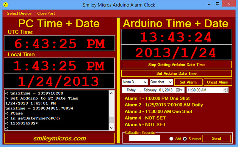
Arduino Alarm Clock (AAC) PC Application.
Now, at Workshop 57, we are at Part 4 of the proto shield alarm clock series — this time mainly discussing software. Believe it or not, these nine Workshops are all related. What we have here is a series that could have been titled Arduino Fritzing Prototype to Production.
What we have done is to learn how to use the Arduino and Fritzing to take a concept from the first stages: a breadboard design, through a PCB (printed circuit board) prototype, to a production PCB. We've used an Arduino alarm clock as the demonstration project around which to hang the entire prototype to production learning.
So, naturally along the way, it got a bit confusing as to what we were really doing. Were we learning how to use Fritzing or learning to use the proto shield, or learning to design an alarm clock?
The answer is yes — we were doing all of that. Don't worry, however, we are coming to the end of the tale of how to use Fritzing to take an Arduino design from prototype to production — and don’t forget, we've also learned a lot about computer based alarm clocks.
I assure you the leaves fit the trees that fit the forest that we are trudging through. So, if while following me I moved a branch out of my way, then let it go and it smacked you in the face — sorry about that. Next time, you can lead the way.
Process_Alarms Module
This fourth module in our project processes the alarm functions. Recall that, in our last episode, we discussed the first three modules: Alarm_Clock, Commander, and Date_Time. We usually think of an alarm clock as having a big button that we can hit to shut off the buzzer in the morning. Our alarm clock, however, is much more capable than a simple wake-up device (besides, the button is tiny and hitting it might not be so easy when you are trying to wake up.)
We are using the example of having an alarm output a piezo tone and a button to shut it off, but this alarm can be adapted to pretty much control anything that an Arduino can control, and respond to pretty much anything an Arduino can respond to. We can adapt this code for use with a datalogger or an industrial controller or whatever we might imagine that needs to keep track of dates and times.
The go_alarm#() Functions
We've already seen that the Arduino loop() function in the Alarm_Clock module calls the alarm functions once per second when the check_alarm variable is set to 1 by the timer. When all the alarms have been checked, the check_alarm variable is set to 0 so that loop can skip checking the alarms. Each of the alarm functions is named go_alarm#() where # is 1 to 5. Now, let's look at these go_alarm functions.
Each alarm has seven eight-bit variables (uint*_t) associated with it: four are used to store the 32-bit Unix datetime variable; one holds the type of the alarm; one tells if the alarm is set; and the last tells if the alarm is tripped.
Check to See if the Alarm has Tripped
Each go_alarm function first checks the alarm#_is_set variable. If it is set, then it compares the alarm time with the current time, and if the current time is equal to or greater than the alarm, then the alarm is 'tripped' and the alarm#_is_tripped variable is set to 1. The user can then decide to handle the alarm immediately in the go_alarm function or leave this to another function in the loop() cascade that checks the alarm#_is_tripped variable.
I would recommend only using the go_alarm function for the alarm if you want to do something short and quick. You would not want to do something like run a tune on the piezo that continues until the button is pushed. For that, you might turn on the piezo tone generator, then return to the loop() where you'd loop until the button has been pressed and then turn off the piezo.
Running the Piezo Buzzer in the Background
We created our piezo buzzer part using Fritzing in Smiley's Workshop 52, then we learned how to use it in Workshop 53. We found that the piezo is loudest at 4,300 Hz, and we saw how to make alarm patterns using the delay() function. However, the delay() function blocks the processor and we don't want to miss anything while waiting around for a beep to complete. So, we need to do something different.
We already have a timer interrupt that trips once per second, and we could use that to turn the piezo on or off in one second intervals. That is pretty long, though, so let's redo our timer interrupt to trip every 250 milliseconds so we can have shorter beep patterns.
Redo the Interrupt Timer
We were using the one second interrupt to set the check_alarm flag in the loop() function. We can continue to do this by keeping the new variable check_alarm_count that we increment every 250 ms and set the check_alarm flag when it has incremented four times. Then, we set it back to 0. We add the count variable at the top of the Alarm_Clock module:
// A timer is used to set the check_alarm flag  <br />
int check_alarm = 0;<br />
int check_alarm_count = 0;
Then, we change the myTimer interrupt to keep the count:
  if(check_alarm_count++ >= 3){<br />
    check_alarm = 1;<br />
    check_alarm_count = 0;<br />
  }
This causes the check_alarm flag to be set once per second as before. Now, we are free to use the timer for 250 ms events, so let's design some piezo beep patterns.
Making Piezo Alarm Patterns
For this demonstration, we will create four alarm beep patterns.
- Three short beeps (250 ms on, 250 ms off).
- Three long beeps (500 ms on, 250 ms off).
- SOS (three short, three long, three short);
- Warble3 — two tones, 250 ms of 4,000 Hz, 250 ms of 4,300 Hz, 250 ms off, repeated three times.
[If you are a regular C programmer, this code is moderately cringe worthy, but since it is educational and for relative novices, I choose to make it easy to understand and not C efficient.]
int three_short_beep = 0; // 0 for off, not 0 for on
int three_short[] = { 1, 0, 1, 0, 1, 0, 2};<br />
int three_long_beep = 0; // 0 for off, not 0 for on<br />
int three_long[] = { 1, 1, 0, 1, 1, 0, 1, 1, 0, 2};<br />
int sos_beep = 0; // 0 for off, not 0 for on<br />
int sos[] = { 1, 0, 1, 0, 1, 0, 0, 1, 1, 0, 1, 1, 0, 1, 1, 0, 0, 1, 0, 1, 0, 1, 0, 2};<br />
int warble3_beep = 0; // 0 for off, not 0 for on<br />
int warble3[] = { 1, 2, 0, 1, 2, 0, 1, 2, 0, 3};<br />
int beep_count = 0;
// Rather than use the loop to check the alarm<br />
// continuously and thereby adding quite a load<br />
// on the processor, we will use a timer set<br />
// to 250 ms.<br />
void myTimer1()<br />
{<br />
  if(check_alarm_count++ >= 3){<br />
    check_alarm = 1;<br />
    check_alarm_count = 0;<br />
  }
  if(three_short_beep){    <br />
     if(three_short[beep_count] == 0) noTone(8);<br />
     else if(three_short[beep_count] == 1)<br />
     tone(8,4300);<br />
     else if(three_short[beep_count] == 2){<br />
       three_short_beep = 0;<br />
       beep_count = -1;<br />
     }<br />
     beep_count++;<br />
  }<br />
  if(three_long_beep){<br />
     if(three_long[beep_count] == 0) noTone(8);<br />
     else if(three_long[beep_count] == 1)<br />
     tone(8,4300);<br />
     else if(three_long[beep_count] == 2){<br />
       three_long_beep = 0;<br />
       beep_count = -1;<br />
     }<br />
     beep_count++;<br />
  }  <br />
  if(sos_beep){<br />
     if(sos[beep_count] == 0) noTone(8);<br />
     else if(sos[beep_count] == 1) tone(8,4300);<br />
     else if(sos[beep_count] == 2){<br />
       sos_beep = 0;<br />
       beep_count = -1;<br />
     }<br />
     beep_count++;<br />
  }       <br />
  if(warble3_beep){<br />
     if(warble3[beep_count] == 0) noTone(8);<br />
     else if(warble3[beep_count] == 1)<br />
     tone(8,4000);<br />
     else if(warble3[beep_count] == 2)<br />
     tone(8,4300);<br />
     else if(beep_count >= 3){<br />
       warble3_beep = 0;<br />
       beep_count = -1;<br />
     }<br />
     beep_count++;<br />
  }   <br />
}
These alarms continue as long as the variable (three_short_beep, three_long_beep, sos_beep, or warble3_beep) in the first if() statement is not 0. We will use the button detection to set all these variables to 0, thus turning off any alarm.
Once per second, the myTimer interrupt checks to see if an alarm is set and, if so, it calls the alarm handling function. Below we see the alarm function for alarm 1:
void goAlarm1(){<br />
#if defined(DEBUG)   <br />
  Serial.println(F("go_alarm1"));<br />
#endif<br />
  if(alarm1.is_set){<br />
    DateTime now = RTC.now();  <br />
    if(now.unixtime() >= alarm1.<br />
    datetime.unixtime()){<br />
      #if defined(DEBUG)<br />
      Serial.println(F("Alarm1 tripped!"));<br />
      #endif<br />
      alarm1.is_tripped = 1;      <br />
      if(alarm1.type == 0){// If it is one shot,<br />
                         // unset it<br />
          unsetAlarm('1'); // this also clears<br />
                         // the EEPROM data   <br />
      }<br />
      else if(alarm1.type == 1){// if daily,<br />
      add 24 hrs to the alarm<br />
        #if defined(DEBUG)<br />
        Serial.print(F("Old alarm date time =<br />
        "));<br />
        showDate("alarm1",alarm1.datetime);<br />
        #endif<br />
        // Add one day, 86400 seconds<br />
        DateTime temp(alarm1.datetime.unixtime()<br />
        + 86400L);<br />
        alarm1.datetime = temp;<br />
        #if defined(DEBUG)<br />
        Serial.print(F("New alarm date time =<br />
        "));<br />
        showDate("alarm1",alarm1.datetime);<br />
        #endif<br />
        // Write new alarm data to EEPROM<br />
        writeAlarm(1,alarm1);          <br />
      }// if alarm1 is daily<br />
    }// if now > alarm1<br />
    <br />
    // Do what you wanted to do with this alarm<br />
    // if it is tripped<br />
    if(alarm1.is_tripped){   <br />
      // if the button state is not pressed,<br />
      // run the alarm<br />
      if(!buttonState) warble3_beep = 1;<br />
      else {<br />
        alarm1.is_tripped = 0;<br />
        // turn this alarm off<br />
        warble3_beep = 0; // turn the beep off  <br />
      }     <br />
    }// if alarm1.is_tripped<br />
  }// if alarm1._is_set  <br />
}
This function first checks to see if the alarm is set and if so, it sets the alarm#_is_tripped global variable so that other sections of the code can know that the alarm has been tripped. It then checks the alarm type. If the alarm is type 0 — a one-shot alarm — it “unsets” the alarm which also clears the EEPROM data for the alarm. If it is type 1 — daily — then it adds 24 hours (in seconds) to the alarm datetime variable so that it will trip again in a day.
Next, it checks to see if the alarm is tripped and, if so, it then runs the process for the alarm. In the above case, that process is to activate the warble3_beep and turn off the alarm (this one doesn't use the button). The piezo will then run the warble3_beep sounds. The whole process will repeat in a day. If we had not set the alarm1.is_tripped to 0, the piezo sound would repeat until the button is pressed.
Accuracy and Calibration
DS1307 Accuracy
If you've been following along and built one of these Arduino alarm clocks, in among all the excitement of learning new things you may have had a moment of disappointment when you realized that this thing isn't keeping time as accurately as you'd like. Mine gains about eight seconds a week. Well, bah! That's 416 seconds in a year — almost seven minutes. Don't panic yet! We can fix this — more or less — sort of. First, let's see what the DS1307 datasheet has to say about this issue:
The accuracy of the clock is dependent upon the accuracy of the crystal and the accuracy of the match between the capacitive load of the oscillator circuit and the capacitive load for which the crystal was trimmed. Additional error will be added by crystal frequency drift caused by temperature shifts. External circuit noise coupled into the oscillator circuit may result in the clock running fast.
Our crystal is rated at ±20 ppm (parts per million), so this would give ±20 seconds in a million seconds (a million seconds is 16666.7 minutes, which is 277.7 hours, which is 11.6 days). Run the math and you get ±1.7 seconds per day (about ±10.3 minutes per year). Mine is gaining 1.23 seconds per day, so it is well within that specification. So, the RTC (real time clock) may gain or lose up to 12.3 seconds per week.
The amount that it gains or loses may vary depending on the ambient temperature. If the RTC is kept at a relatively constant room temperature, for example, then the gain or loss will be pretty constant over a long time period (years). In a moment, we'll see how to use an alarm to help keep the clock more accurately calibrated.
Maybe You Don't Want to Use It Outdoors
If the RTC is kept outdoors, then it will be subject to daily and seasonal temperature variations. The daily variations might average out over time, meaning that in any given week one might expect fluctuations to yield some sort of weekly mean that will change slowly from one week to the next.
For example, if a given week has highs mostly in the 70s and lows mostly in the 40s, then the mean will be in the mid 50s for that week. One might expect that the preceding week and the following week would also be more or less in the same range, and thus a calibration covering one week will be much the same as the following week.
When seasons change, however, the weekly mean temperature will rise or fall enough so that a calibration may be very different from that in another season. For a weekly calibration in the summer, it could be +10 seconds, while a weekly calibration in the winter could be -5 seconds.
For this reason, if you are going to design an RTC for the outdoors or anywhere with drastic temperature variations, I would recommend using an RTC with a built-in thermometer for automatic temperature compensation like the DS3234.
More Accurate RTC With Built-in Thermometer
Our DS1307 costs about $4 in singles from Mouser. They have another RTC — the DS3234 — with a built-in thermometer for about $8.35 in singles. It has an accuracy of ±2 minutes per year. Although I personally think it is worth the price, it only comes in surface-mount, so we'll stick with the through-hole DS1307 and provide a calibration technique that might make it nearly as accurate as the expensive one.
Calibrating Your Arduino Alarm Clock
I ran my AAC for a couple of weeks and checked it more or less daily to determine that it is gaining 1.23 seconds per day. We calculate that a day has 86,400 seconds and since 1.23 seconds per day is the same as 0.813 days per second, we can multiply the days per second times the seconds per day and get 70,244 seconds (70244.9 rounded up).
This is the number of seconds it takes for our AAC to gain one second. So, if we set an alarm to go off every 70,244 seconds and subtract one second from our 'real' time, we correct for the gain. I'm not sure how accurate this will be over the long term, but I'd speculate that it would be at least as accurate as the more expensive part.
Now, what we need to do is add a command in the PC AAC application to send the Arduino the calibration seconds, and whether to add or subtract a second at each interval. Then, in the Arduino, we need to build an alarm in the AAC that goes off every 'calibration' second, and either adds or subtracts a second depending on what it was told. [Yes, we could further automate this process so that we wouldn't have to manually calculate the calibration seconds, but I figure we'll only need to do this once, so for me, it isn't worth the extra effort.]
Let's review how we set and check alarms so that we can see how to add the calibration alarm. In the Commander module, we parse the input bytes from the PC in the commandArray[] and see that the first byte is the character 'A.' Then, we call the ACase() function where we further parse the input bytes, noting that the second byte in the commandArray[1] is the number of the alarm (1 to 5).
We then call the setAlarm() with the parameter being the pointer to the DateTime class instance for that alarm. The setAlarm() function then reads the rest of the commandArray bytes to get the date and time to set the alarm, and loads that into the specific alarm instance.
Once the data is loaded, then we can retrieve the unixtime for that alarm (which you may remember is the number of seconds since January 1, 1970). Now that the alarm is set, our timer interrupt sets the check_alarm flag once per second, and the loop() function looks to see if that flag is true.
If it is, then it checks each alarm to see if it is set. If it is, then it calls the function specific to that alarm. That specific alarm function then does whatever it is programmed to do and finishes off by setting the check_alarm flag to false.
We will create a new command 'C' to handle the calibration alarm process, but we will try to use as much of the regular alarm process as makes sense. We will look at the Arduino side of this next time. For now, let’s see how the PC application is modified to send the data.
Modify the PC Application
We need to send a calibration number and whether to add or subtract a second to the AAC. So, let's use a text box for the number and two radio buttons for the add or subtract. We'll also need a send button when we've input the data so that data is sent to the AAC.
The calibration number will need to be 32 bits to accommodate the value, so to simplify things we'll break the number into four bytes and send them separately. We'll also send a fifth byte with either 0 for subtract or 1 for add. The Arduino will then parse this input packet and set the calibration alarm.
Note in Figure 1 that we've added a Calibration Seconds panel to the PC application that lets the user enter the number of seconds to use as an alarm to either add or subtract a second, depending on which radio button is pressed.

FIGURE 1. Calibration panel.
When you press the Send button, you get the message shown in Figure 2 that shows the AAC returns that it was in CCase (if you are in the debug mode). It returns the number you sent along with the add/subtract state so you can verify that what it thinks it got is what you think you sent.
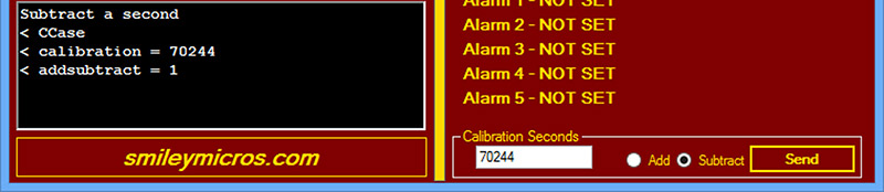
FIGURE 2. Valid calibration value.
The C# Calibration Seconds Function
This wasn't quite as simple as some of the other additions we've made, but the following C# code for the PC should be somewhat self-explanatory.
It was a bit of a hassle figuring out how to translate the user input into bytes that can be sent to the AAC, and the methods chosen may not be the most efficient.
However, they work, so let’s move on.
// Algorithm copied from MSDN and modified for<br />
// this use<br />
private void buttonSendCalibration_Click(object sender, EventArgs e)<br />
{<br />
     string calibration;<br />
     UInt32 numVal = 0;<br />
     var val = new Byte[7];<br />
     Byte addsubtract = 0;
     if (radioButtonAdd.Checked == true)<br />
     {<br />
         richTextBoxReceive.Text += “Add a<br />
         second\n”;<br />
         addsubtract = 0;<br />
   }<br />
   else if (radioButtonSubtract.Checked<br />
   == true)<br />
   {<br />
         richTextBoxReceive.Text += “Subtract<br />
         a second\n”;<br />
         addsubtract = 1;<br />
   }
calibration = textBoxCalibrationSeconds.Text;
   // ToInt32 can throw FormatException or<br />
   // OverflowException.<br />
   try<br />
   {<br />
       numVal = Convert.ToUInt32(calibration);<br />
   }<br />
   catch (FormatException)<br />
   {<br />
      richTextBoxReceive.Text += “Input string is not a sequence of digits.\n”;<br />
      return;<br />
  }<br />
  catch (OverflowException)<br />
  {<br />
      richTextBoxReceive.Text += “The number<br />
      cannot fit in an Int32.\n”;<br />
      return;<br />
  }         <br />
    <br />
  val[0] = Convert.ToByte(‘C’);<br />
  val[1] = (Byte)(numVal & 0x000000FF);<br />
  val[2] = (Byte)((numVal & 0x0000FF00) >> 8);<br />
  val[3] = (Byte)((numVal & 0x00FF0000) >> 16);<br />
  val[4] = (Byte)((numVal & 0xFF000000) >> 24);<br />
  val[5] = addsubtract;<br />
  val[6] = Convert.ToByte(‘!’);
  serialPort1.Write(val, 0, 7);<br />
}
I got the PC application algorithm from MSDN and it had a couple of error catches that help the user to get the calibration number correct. Figure 3 shows catching the error that the number is too large, so it isn’t sent to the Arduino.
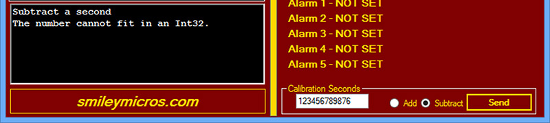
FIGURE 3. Calibration value too large.
Another error catch in Figure 4 shows what happens if you send something that isn’t a number like 70244a. This won’t catch every kind of error, but we can assume some level of good sense in the user, so it should suffice.
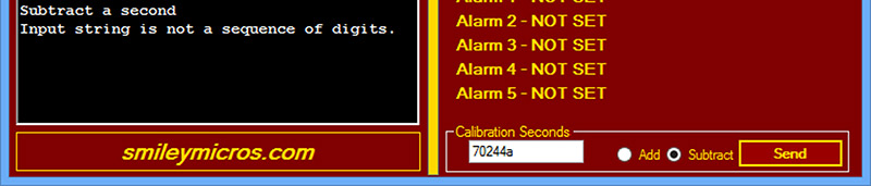
FIGURE 4. Calibration value not a number.
In our next Workshop, we will continue learning how to calibrate the AAC by looking at the Arduino code for this process. We need to add or subtract a second after a specified period, then repeat the process. I bet you think it will be easy?
Well it wasn’t for me, but then nothing ever is — tune in next time! Remember all this mix of software and hardware is part of our long term learning about Arduino Fritzing Prototype to Production. NV
The Arduino proto shield alarm clock kit lets you build an alarm clock circuit on a breadboard and port that circuit to a PCB. This kit is the basis for my presentation of how to do a complete Arduino design cycle using Fritzing to go from a breadboard prototype, through schematic creation and breadboard layout, and finally producing your own printed circuit board. You can get the kit or materials that support this learning activity from the Nuts & Volts webstore.