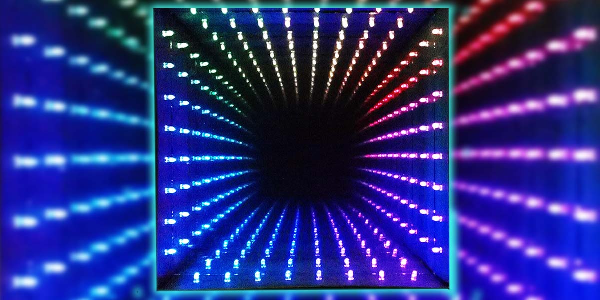
Okay, I’ll admit it. I’m a sucker for colored flashing lights — especially if controlled by a microprocessor (uP). So recently, when I came upon a really good deal on RGB LEDs and another really good deal on the Arduino Uno processor board, I knew I had to build something but I wasn’t quite sure what. As luck would have it, as I was clearing out my parents home, I found an Infinity Mirror I had purchased for my father back in the 1980s. All of a sudden I knew what I should build: an updated version of an infinity mirror with multi-color LED light sources controlled by an Arduino. Since this was to be a major update to the infinity mirror concept, I decided to call my creation an Infinity Portal.
For those not familiar with what an infinity mirror is, it's usually a smallish enclosure similar to a shadow box that one looks into which has light sources (typically white) around the interior perimeter. The single layer of lights looks to extend far beyond the depth of the enclosure with the lights seeming to repeat 20 to 30 times in concentric patterns. So, in other words, the reflected lights seem to go on for six to eight feet inside of an enclosure that is only inches deep.
I had to determine just how the infinity mirror effect was accomplished if I was going to build one. It turns out the effect is easy to reproduce. Regardless of the size or shape of an infinity mirror, they are all based on the same concept and construction.
Internally, an infinity mirror consists of one fully reflective mirror, one partially reflective/partially transparent mirror, and the light sources sandwiched between them. When a light ray from a light source strikes one of the mirrors, the ray is reflected in accordance with the Law of Reflection: The angle of incidence equals the angle of reflection. The reflected image then reflects off the second mirror back toward the first, and so on to infinity, assuming the mirrors are parallel. The details of the pattern are altered by distortions and reflective losses in the semi-transparent mirror, small variations in the angle of the mirrors, and by the view point from which the pattern is observed.
So, to build an Infinity Portal requires an enclosure of some type, a fully reflective mirror mounted in the rear of the enclosure, a series of uP controlled RGB LED light sources, and a partially reflective mirror through which the observer looks. Hardware aside, we also require some clever software to drive the LEDs in bright, creative, and colorful ways. Figures 1 and 2 show the Infinity Portal I built that will be discussed in this article.
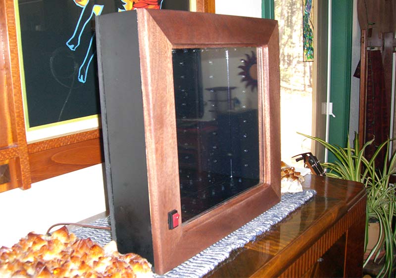
FIGURE 1. My enclosure measures 17” x 17” x 4.75” and is constructed from MDF and walnut wood.
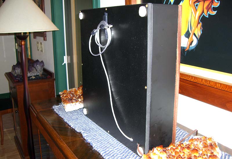
FIGURE 2. PLEASE NOTE: The USB programming cable and power cable protrude from the rear of the portal. I used Velcro® to secure the USB cable when not in use.
Commercial examples of infinity mirrors can be found at http://lightenergystudio.com/infinitymain.html among other places on the Internet. As with any one-off project like this, I experienced a few issues while building my portal which I'll describe at the appropriate points in the article. I'll also describe how the hardware and software for the Infinity Portal work but I will leave the packaging to you and your imagination. I made my enclosure out of half inch MDF (medium-density fiberboard) which I painted black with a facade made of walnut.
The Portal Hardware
There are 32 RGB LEDs used in this design with eight mounted on each of the four sides of the enclosure. When you consider that each RGB LED is really three separate LEDs in a single package, you soon realize that we are really talking about controlling 96 LEDs in total. Individual control over each LED amounts to a lot of drivers that the uP has to control. Luckily, Texas Instruments produces a chip for just such applications called the TLC5940 (see Resources).
There is a lot to these chips, but for our application you can think of them as made up of a serial shift register driving 16 PWM (Pulse Width Modulated) constant current drivers. These chips are made to be cascaded together to control lots and lots of LEDs, but even with 16 channels of control per chip it would require six TLC5940s to control 96 LEDs in a typical design.
Fortunately, I used multiplexing in this design to control the LEDs which reduces our TLC5940 chip count to just two devices. Each LED channel supports 12 bits of PWM brightness data which range in value from 0 (off) to 4095 (full brightness).
NOTE: TLC5940s are constant current sinks, so they must be used with common anode RGB LEDs.
One issue I had while building my portal was the mass of wiring needed to connect all 96 LED channels to the controller hardware. I used small gauge solid wire to connect the LEDs but even so, the wire bundle was bigger than I had anticipated which made the space in my enclosure cramped to say the least. Keep this fact in mind when deciding how to package your portal. The insides of my portal are shown in Figure 3.
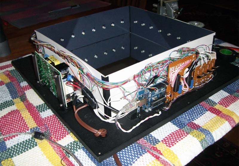
FIGURE 3. All components were mounted to the back of the enclosure with the exception of the power switch and the partially reflective mirror which are mounted on the front. The power supply is shown on the left. The Arduino Uno (blue PCB) is near the front and the custom circuitry is built onto two brownish perf boards on right. The 32 RGB LEDs are mounted on black matt boards which frame the rear 12” x 12” mirror. The USB programming cable is attached to the Arduino and passes out the back of the enclosure through a hole.
LED multiplexing requires both hardware and software support. In terms of hardware, I divided the 32 RGB LEDs into four rows of eight. Each of the rows have a common buss to which the anode lead of each LED in the row is connected. See the schematic in Figure 4 for clarification.
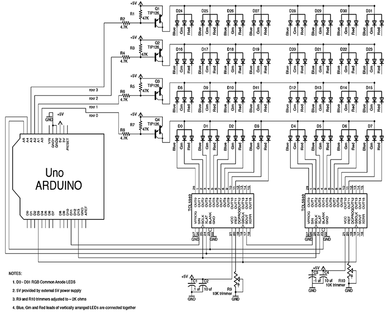
FIGURE 4. The Infinity Portal schematic.
A PNP power Darlington transistor — controlled via a digital output pin from the Arduino — controls the current source for each row. When the digital output is low, current flows to the LEDs in a given row. When the digital output is high, all LEDs in the row are turned off. While multiplexing, only one row of LEDs should be on at a time.
Serial data for controlling each LED channel is fed to the two cascaded TLC5940 chips via the SPI (Serial Peripheral Interface) provided by the Arduino. Data is shifted out in big endian format with the most significant bits going first. The three color LEDs which comprise an RGB LED are connected to sequential TLC5940 channels. The blue LED channel is the least significant while the red LED channel is the most significant. As designed, only 12 of the 16 channels available on each TLC5940 are being used. You, however, could use all of the LED channels.
The current available for each channel’s constant current sink is set by a resistor connected to pin 20 of each TLC5940 chip. In my design, I used 10K ohm 20-turn trimmers for setting the current. I have the current set to around 20 mA and the LEDs are plenty bright enough even with multiplexing. As set, all of the components in the Infinity Portal run cool to the touch which is important for an enclosure without ventilation.
I had a few requirements for powering the portal. First, I didn’t want to use a wall wart type of supply because I didn’t want any electricity consumed when the portal was turned off. Second, I wanted to power the portal with just a single 5V supply. Finally, I thought it better to buy a regulated power supply instead of building one myself.
In looking around, I found a surplus 5V/12 amp power supply with over and under voltage protection and current limiting that was small (3” x 5” x 1”) and cheap. A 12 amp power supply was severe overkill as the portal will run from the power supplied by the USB cable from my MacBook Pro laptop. Any power supply capable of a couple of amps at 5V will easily power the portal with plenty of reserve power to spare.
The Portal Software
It turns out using an Arduino processor to control TLC5940 chips for control of LEDs and stepper motors is a popular pasttime. So much so that an Arduino library exists for TLC5940 chips.
This library (see Resources) was provided to the Arduino community by Alex Leone and is controlled in accordance with the GNU General Public License. By using this library, you needn’t understand all of the details of the Arduino/TLC5940 interaction.
The TLC5940 library exists in two forms. The first is for controlling TLC5940 chips serially chained together and the second one is for controlling TLC5940s used in multiplexing schemes. Unfortunately, the multiplexing version of the library doesn’t work as provided, but can be made to work with a few small changes to the hardware design and the library code. See http://www.arduino.cc/cgi-bin/yabb2/YaBB.pl?num=1286580054 for the details if you're interested.
The design presented here implements these changes allowing multiplexing to work. For those of you who haven’t worked with the Arduino before, there is a free set of development tools available (see Resources). Figure 5 shows the Integrated Development Environment (or IDE) which comes with the tools package. It's both simple and useful for Arduino code development.
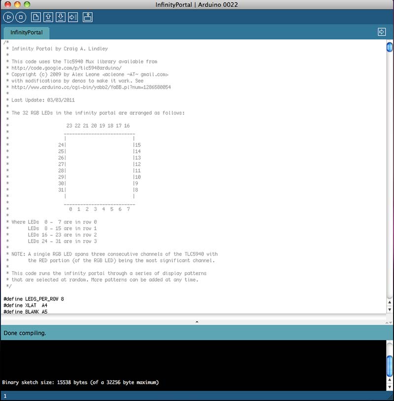
FIGURE 5. Displaying the InfinityPortal.pde code.
The Arduino programming language is based on C/C++ so it should be familiar to many. There are two entry points to all Arduino programs: setup() and loop(). The setup() function is called first; it's within this function where you do all hardware initialization. Subsequently, the loop() function is called which contains all of the operational code for your program.
Once you have downloaded and installed the Arduino tools on your development machine, you connect a USB cable to your Arduino processor board. After writing and verifying (compiling and linking) your code, you click a button in the IDE to transfer the executable code to your target. Print statements to the pseudo serial port in the code provide a means of debugging your program.
The file InfinityPortal.pde (available in the downloads) is the sum total of all the code I developed for the Infinity Portal. This file contains the fixes to the TLC5940 library, code for configuring the library for multiplexing, and the code for each of the display patterns (of which there are currently 24) used in the portal. In its current form, the Infinity Portal’s code selects display patterns randomly from the time the portal is turned on until it's turned off.
Before showing how display patterns are developed, it's interesting to note there are two asynchronous processes running simultaneously within the code. These are referred to as the foreground and the background process. Both these processes share a single data buffer; the foreground process puts data into the buffer and the background process shifts the data out of the buffer to the TLC5940 chips.
The background process runs at interrupt time when the PWM timer times out indicating the full PWM cycle for controlling LED brightness has completed. A counter called shiftRow is consulted at interrupt time to determine which row of the multiplexed LED data is to be shifted out to the TLC5940s, and then which of the four row selects is pulled low enabling that row of LEDs. Afterwards, shiftRow is incremented so that a different row will be selected next interrupt time. This background process repeats continuously without regard for the actual data that is being sent to the TLC5940s for each row. The foreground process is where display patterns run.
Code implementing the display pattern writes data into the shared data buffer where the background process picks it up and sends it out. It's important to understand/remember that once data is placed in the data buffer, it stays there until overwritten. If you want to light an LED and then turn it off, you have to first set the data and then zero the data to turn it back off.
There's a lot of code in InfinityPortal.pde, but you can ignore most of it. What you must understand is that the 32 LEDs are addressed by number (0 .. 31) (as shown in the inset in Figure 5).
Functions from the code that are used for pattern development are shown in Table 1.
| Function Name |
Operation |
| TlcMux_clear(); |
Clears the data buffer causing all LEDs to turn off. |
| delay(milliseconds); |
Delays program execution for specified number of milliseconds. |
| setLEDOff(ledNum) |
Turns the specified LED off. |
| setLEDRGB(ledNum, red, green, blue) |
Set ledNum LED to the specified red, green, and blue values. Valid values 0 .. 4095. |
| void setLEDRGB(ledNum, struct RGB rgb) |
Same as above except a structure contains the RGB value to set. |
Table 1.
As an example, the following code turns all LEDs on in an alternating red/green pattern:
TlcMux_clear(); // Turn off all LEDs
for (int i = 0; i < 32; i++) {
// Loop through all 32 LEDs
if (i % 2 == 0) {
// Is this an even numbered LED ?
setLEDRGB(i, 4095, 0, 0);
// Turn ith LED to red, full brightness
}
else {
setLEDRGB(i, 0, 4095, 0);
// Turn ith LED to green, full brightness
}
}
As mentioned, the Infinity Portal has 24 display patterns built in. As the simple code illustrates, it's really easy to add new patterns or change existing ones.
Portal Packaging
There is no end of possibilities for packaging an Infinity Portal. I’ve seen infinity mirrors packaged in a square box (similar to what I did), in a rectangular box, a triangular box, a round box, and even a star-shaped box. The important things are to have the semi-transparent mirror facing the viewer and to have the mirrors mounted parallel to each other. The light sources (RGB LEDs) are mounted around the perimeter of whatever enclosure you use, spaced half way between the parallel mirrors.
If the lights are not equally spaced between the mirrors, the reflections you see in the portal will be unequally spaced. This may be an effect you want to utilize in your packaging. Since I have access to woodworking tools, I made my portal out of MDF with walnut trim as I mentioned earlier. Once finished, the MDF box was painted black as this color scheme matches the furniture in our living room where the portal resides. Finally, a word must be said about the partially reflective mirror used in the portal.
Three possibilities were investigated: “one way mirror” glass; partially reflective acrylic; and the use of reflective window film over plain glass.
For cost considerations, I decided to use mirrored window film available at most hardware stores over plain glass. The film must be applied to the glass using soapy water so that it lays out flat with a minimum number of bubbles. This is easy to do after a little practice.
I hope you’ll enjoy this project for a long time ... to infinity and beyond. NV
Parts List
| Designation |
Value |
Source/Notes |
| C1, C3 |
.1 µF capacitors |
Anywhere |
| C2, C4 |
10 µF capacitors |
Anywhere |
| D0-D31 |
RGB LEDs common anode |
ebay.com |
| Q1, Q2, Q3, Q4 |
TIP126 Darlington transistors |
allelectronics.com |
| R1, R3, R5, R7 |
47K ohm 5% resistors |
Anywhere |
| R2, R4, R6, R8 |
4.7K ohm 5% resistors |
Anywhere |
| R9, R10 |
10K ohm 10 turn trimmers |
RadioShack |
| U1, U2 |
TLC5940 LED drivers |
ebay.com |
| Power Supply |
Five volt/two amp minimum power supply |
allelectronics.com |
| Processor Board |
Arduino Uno |
ebay.com |
| N.A. |
Perf board |
RadioShack |
| N.A. |
Hookup wire |
Used phone wire |
Check out www.superbrightleds.com or www.ledtronics.com for LEDs.