With this unit, you can have a high performance power amplifier for a low cost. The performance actually depends more on the design than on expensive components. Since the time when solid-state amplifiers were first designed using early power transistors, a great deal has been done to improve them. This article will show you how to construct an inexpensive amplifier; the power supply described here will run two channels.
Safety First!
If you have been working with digital circuits and processors, you are probably used to working with five volt power supplies and know the basic precautions to take. This amplifier will have about 35 volts from heatsink to heatsink — enough for a fair shock if you have wet or sweaty hands. So, don’t touch both heatsinks at once, in particular one with each hand!
Also, don’t work with a ring or metal wristband on. Filter capacitors hold considerable energy and getting a metal band across one might cause considerable heating. Always wrap the fuse and power switch connections with tape or use heat shrink tubing on them before applying any power. This at least limits your exposure to only the AC from the transformer and the DC power supply output voltages.
Parts And Assembly
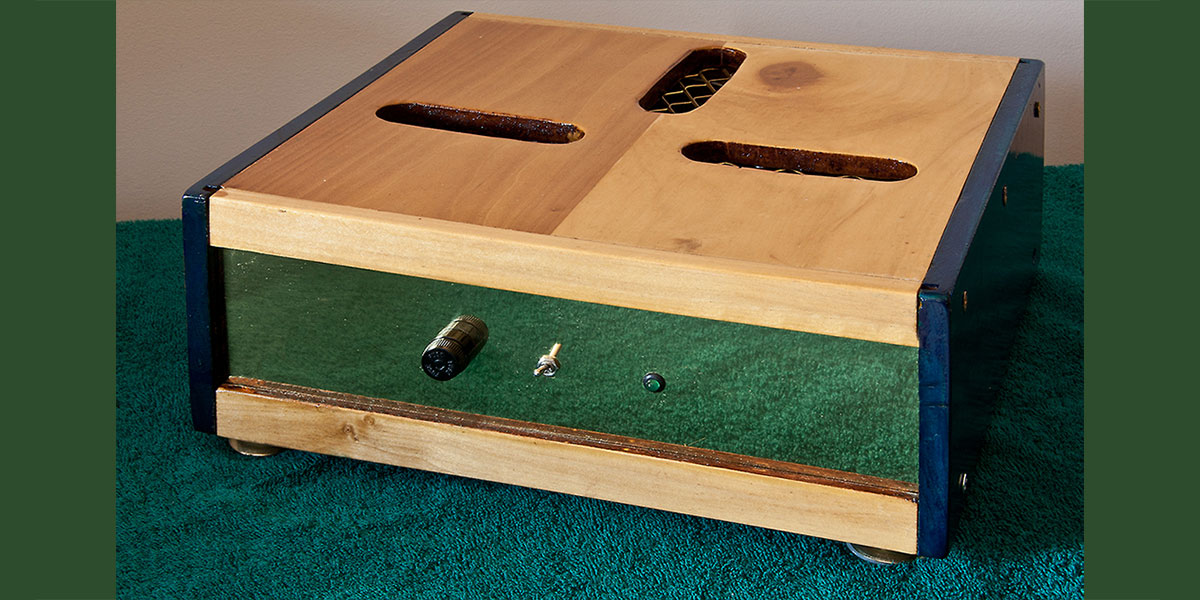
You may question the use of carbon film resistors since metal film ones are quieter. This amplifier checks out at 105 dB signal to noise. To obtain 12 watts out, we will use a 25 volt CT transformer rated at two amps. You can increase the power output to 30 watts by using a higher voltage and current power transformer. We’ll discuss this later. The amplifier in Figure 1 is a 30 watt version.
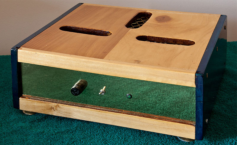
FIGURE 1. Power amplifier in wood case.
The power transistors — leads down, label facing you — have the base, collector, and emitter in that order. The small signal transistors — flat facing you and leads down — are emitter, base, and collector in that order.
Heatsinks might come with a graphite impregnated fiberglass backing. This is a heat conducting layer that conforms to the transistor mounting surface and is NOT an insulator. With it, you don’t need heatsink compound. Be sure to debur the hole at the mounting surface.
Sanken transistors have a mounting hole that will clear a 4-40 screw or an M2.5 metric. The plastic case is extremely hard (I suspect it might be ceramic). I tried to drill out the hole just a little for a 6-32 screw and the case cracked; there was no damage to the working parts, it just doesn’t look very nice. I used a separate heatsink for each of the two output transistors.
The bias adjust network has the sensing transistor connected on leads as short as possible and the transistor — a Phillips BD139 or a 2SD669 — is mounted stacked with one of the output transistors, with the mounting surface to the face of the output transistors.
Point the leads in the same direction as those of the power transistor. Choose the one that allows the shortest leads. Heatsink compound between the two is desirable. Use sleeving on the three leads of the transistor.
The temperature on the outside face of the power transistor follows the junction temperature more closely and quickly than the mounting surface and heatsink, so this is the best place to measure the temperature.
Any TO-126 size NPN transistor ought to work well here, but I’ve tested with the two above, with the label facing you; the leads down have connections left to right ECB.
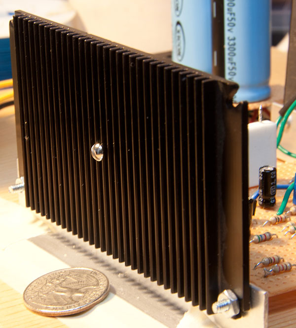
FIGURE 2. This heatsink is adequate.
The output transistors should have their collectors wired directly to the power supply filter capacitors using #16 stranded wire. Twist these wires tightly for as much of their length as is practical. Run the ground wire separately; that is, don’t twist it with the other two. These power wires each carry essentially half wave representations of the output signal. This signal can couple to the input of the amplifier, greatly increasing the distortion at high frequencies. Twisting the supply wires together as far as possible greatly reduces this problem.
Place the output transistors and heatsinks as far away from the input as possible, but keep the leads other than the power to the collectors as short as possible. The power to the rest of the circuit should be connected to the power supply filter capacitors with ordinary hookup wire. Don’t connect the circuit power to the output transistor collector power leads.
It is VERY important to connect the speaker output ground back to the junction of the two filter capacitors in the power supply. Ground to the amplifier must be run separately back to that same “quality ground” point. Also, there are two bypass capacitors; each power voltage to ground (0.1 µF ceramic). The ground for these should be run separately back to that quality ground point, as well.
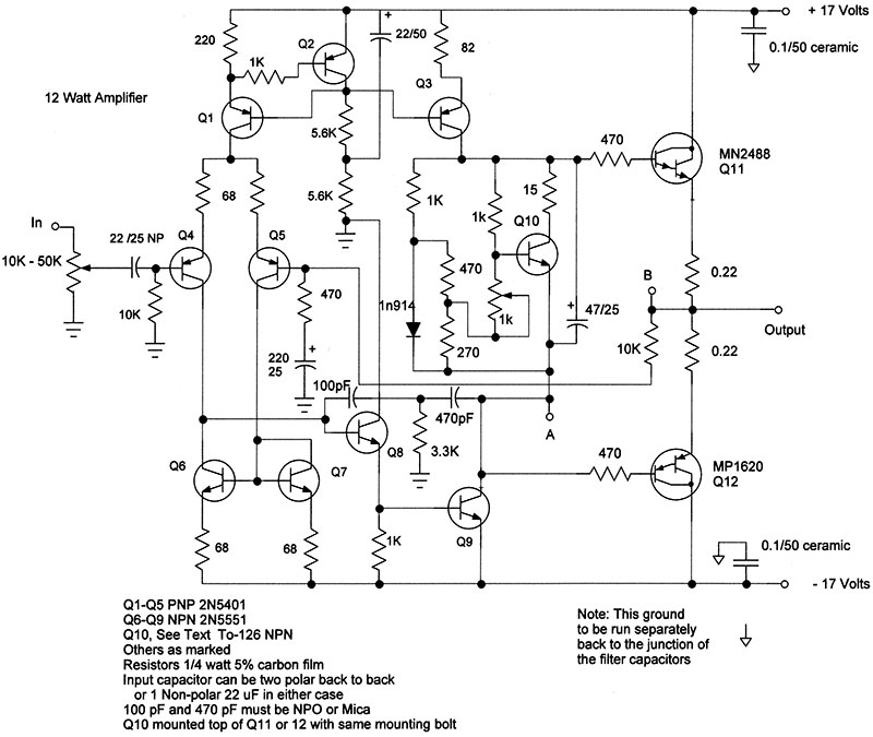
FIGURE 3. Amplifier schematic.
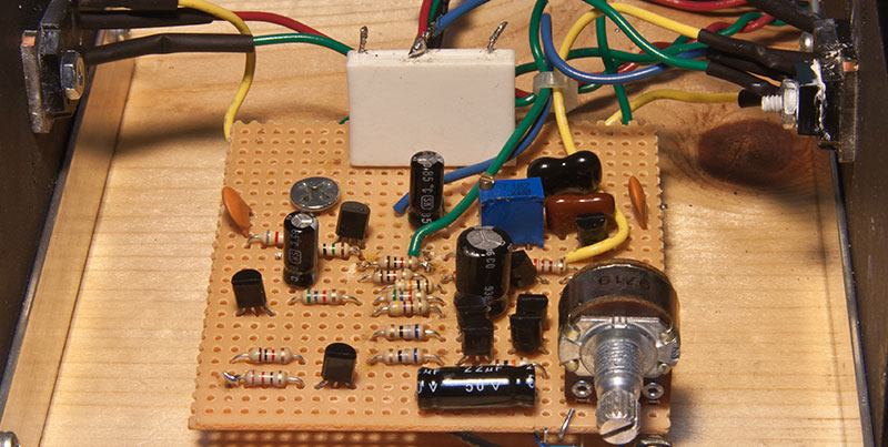
FIGURE 4. Breadboard assembly.
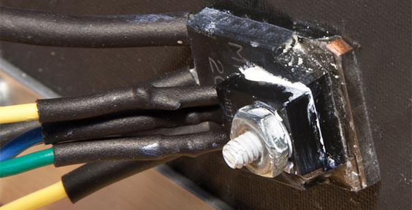
FIGURE 5. Temperature sense transistor detail.
My perf board assembly has an added RCA jack and potentiometer stuck on the corner for testing (Figure 4). The 0.22 ohm resistors are in one package with leads running out both ends for convenience in measuring the voltages. Standard single wire wound resistors may be used as well, of course.
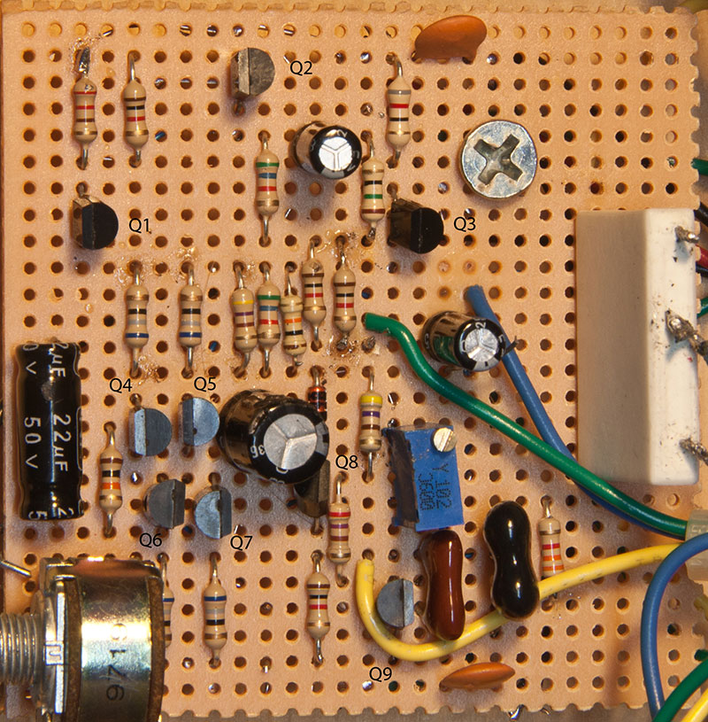
FIGURE 6. Perf board with identification of transistors.
I placed parts roughly as they appear on the schematic. This makes circuit tracing much easier. The top of the board in Figure 6 corresponds to the top of the schematic.
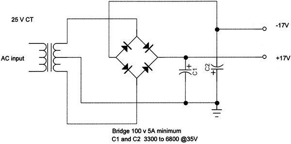
FIGURE 7. Power supply schematic.
You will want a power switch and fuse on the primary side of the power transformer; 3,300 µF capacitors are adequate for both versions of the amplifier. By using the larger ones, you will get a watt or two more out of the amplifier before clipping. You will need to use a slow blow fuse because at turn-on, the filter capacitors essentially look like a shortcircuit as they charge. I suggest two amps. A fuse will not protect the output transistors against an output shortcircuit, but will blow if the power supply is shorted.
This power amplifier is Class B. Class B amplifiers introduce what is called crossover distortion. When the output signal is negative, the PNP output device conducts. When it is positive, the NPN conducts. Crossover distortion is generated at the point where the conduction crosses over from one output transistor to the other. Each transistor requires a small forward bias voltage base to the emitter to make it start to conduct — roughly 0.7 volts. There is an optimum quiescent current through the output stage that minimizes distortion. No setting of this current can eliminate the crossover distortion completely, but the remaining distortion is reduced by the overall global negative feedback.
This current is controlled by the bias voltage applied to the two output transistors. The bias control circuit includes a temperature sensing transistor that reduces the bias voltage as temperature increases, attempting to maintain the bias current at a constant level. If this is not done, as the output transistors get hot, the current increases and can reach a condition called thermal runaway. When that happens, the current increases until one or both of the output transistors is destroyed. These output transistors need a sensing transistor that is closely coupled mechanically. (Refer to Figure 5 again.)
Note that the output transistors have 470 ohm resistors in series with the base connection. These are called stopping resistors. They prevent the output stage from oscillating. I place these resistors right at the base lead of the output transistors and use sleeving over them. Delay connecting the output transistors until preliminary testing is done.
Preliminary Test
With the output transistors NOT connected, connect point A to point B (see schematic). This will be the output point for testing. Before turning on the power, trace your wiring against the schematic wire for wire. Measure resistance from the power connections to ground to be sure there is not a shortcircuit in the wiring.
Turn the volume control down all the way. For a first test, don’t connect a load of any kind. Turn on the power and measure DC voltage from output to ground. It will either be at one of the power supply voltages or nearly so indicating a problem in the wiring; or, it will be within 10 or 20 millivolts of ground indicating proper operation. If it is high, turn off the power and trace the circuit again. By not connecting the output transistors yet, you have probably avoided destroying any of the low level transistors.
Final Test
When the voltage checks out okay here, turn off the power and carefully connect the output transistors. Be sure to remove the connection of point A to point B. Measure and set the 1K bias adjustment potentiometer to maximum resistance. Measure because you might have gotten the CW and CCW ends of the potentiometer reversed. Maximum resistance insures a small bias voltage. Now, turn the power on again and check that the output voltage is on the order of millivolts.
Distortion is reconciled for minimum by adjusting the bias voltage potentiometer while measuring the DC voltage across the two 0.22 ohm resistors in series. Setting the voltage to 26 millivolts, the theoretical best value works fine. This adjustment gets my prototype very close to the minimum distortion point. This is a no signal current of about 59 mA (0.026/0.44 = 0.059 amps).
If you use a 20 turn potentiometer (recommended), it will take several turns of the adjusting screw before you see any voltage across the 0.44 ohms. Don’t turn too rapidly! Wait a while for the transistors to heat up and readjust the bias potentiometer for 26 millivolts again. The heatsink may get warm but shouldn’t get hot with no signal present. Connect the potentiometer as shown back in the schematic. The most common potentiometer failure is that the adjustable contact can open. When connected as shown, this only results in a decrease of the bias voltage to the output stage, reducing the quiescent current to zero. Distortion will increase but no other damage will occur.
Important: You must measure this voltage with a “floating” voltmeter such as a battery-operated digital multimeter. If you use a bench voltmeter that has the common lead grounded, you will destroy the output transistors or at least one of them.
Distortion (%) at 12 watts
1 kHz 0.0016
10 kHz 0.0025
20 kHz 0.0042
Distortion values will vary somewhat with the exact bias setting, but will very likely be below 0.007% at 20 kHz. This is about 1/16 of what is presently considered audible. Sorry, but space here doesn’t permit a discussion of why we are worried about harmonics of 20 kHz (which we can’t hear anyway).
The heatsinks get warmer but not uncomfortable to the touch running the amplifier at eight watts output. The transistors actually dissipate more power at four watts output than at 12 watts — which is near clipping. If you have a signal generator and can run a signal at 1 kHz into the amplifier input — adjusting the level for 5.6 volts output into an eight ohm load — set this up and let it sit for half an hour, testing it with a finger now and then. You can make an eight ohm dummy load by using an eight ohm 10 watt resistor.
I found some 10 watt 24 ohm resistors and paralleled three for a 30 watt load. You can test using a 50 or 60 Hz power line frequency by connecting a transformer — perhaps 6.3 volts centertapped — using only half of the winding and turning the input down with the input level control for the four watt output (5.6 volts into an eight ohm load equals four watts) if you don’t have a signal generator.
Maximum output before clipping is 12 watts 9.8 volts RMS into an eight ohm load. Depending on your filter capacitors and your local line voltage, the maximum output may vary a little. Smaller filter capacitors allow greater ripple voltage, so the signal can run into the ripple minimum points and cause a sudden and sharp rise in distortion as the signal level increases beyond that point.
You will find the output enough for very loud room volume with any fairly efficient speaker. My JBL speakers produce 86 dB sound pressure level at one meter at one watt. My better speakers are 93 dB. The 12 watt amplifier on the more sensitive speaker sounds as loud as a 50 watt amplifier on the JBL. Frequency response of this amplifier is 3 dB down at 400 kHz. This implies negative feedback of about 26 dB at 20 kHz. This is a safe level for stability of the amplifier. A bit more open loop gain would increase the feedback to 30 dB and reduce the distortion by about 1/3 at the expense of less stability.
More Power?
Does 12 watts seem too puny? How about 30 watts? Replace the power transformer with a Triad 36-T8 from Allied Electronics. It is rated at 2.8 amps 36 volts centertapped, and the supply voltage will be on the order of plus and minus 26 volts. Heatsink to heatsink voltage will be 52, which is more than enough to feel. Before changing the power transformer, turn the bias control to reduce the bias voltage to zero. Connecting a higher power supply voltage would increase the bias. After connecting, readjust for 26 millivolts. Use a rectifier bridge rated at 100 volts and five amps or more, and 35 volt or higher filter capacitors.
Rectifier bridges are quite inexpensive. There is no reason not to use one that has a substantially higher current rating than necessary. Orient the heatsink with the fins vertically (this is more important with the 30 watt version) and mount the transistor about an inch up from the bottom at the center of the heatsink. Be sure not to place the heatsink on the bottom of the box; that is, leave half an inch UNDER the heatsink so air can flow directly up through the fins. This makes a significant difference in the maximum heatsink temperature.
I have mounted my heatsinks in previous projects on a piece of 5/8 x 5/8 aluminum angle from the local hardware store. Remember that these heatsinks have the supply voltages on them. Don’t mount the pair to a metal chassis or to a single angle bracket! Because of the voltage present, you should put the amplifier with heatsinks in an enclosed box. Be sure there are ventilation holes below the fins and also at the top of the box. Be sure to fit the box with feet so air can get to the vent holes at the bottom of the box. With this power supply, you will get close to 32 watts out before clipping.
Distortion (%) at 30 watts
1 kHz 0.0011
10 kHz 0.0026
20 kHz 0.0042
The distortion values depend a little on the temperature of the heatsinks; that is, whether the amplifier was just turned on or has been running at 20 watts for a while. In this design, distortion remains low from 1 kHz on down to 20 Hz. If you have inefficient speakers or listen to your music really loud, you should use larger heatsinks.
Manufacturers typically use heatsinks that won’t take maximum output continuously since music peaks are very far above the average. I’ve used these smaller heatsinks in my 30 watt version amplifier successfully. It can be run at 10 or 12 watts, which causes maximum power dissipation in the output transistors for 15 minutes without problems.
The listening level will be a fraction of a watt with reasonably efficient speakers. The heatsinks will barely reach body temperature. The extra power is needed for peaks in the music loudness. Note that with this power transformer at full output on one channel, the power supply voltage is 25.5; at 30 watts, the peak collector current is 2.7 amps. The RMS current is just under two amps. The power supply will run one channel at 30 watts but not both simultaneously. This is normal design practice among amplifier companies. Average output power playing music will be well below any problem level.
Last Notes
My home stereo system uses an amplifier of this design. The most usual comment I get from listeners to my system is that it sounds “clean.” I’ve substituted my breadboard of this amplifier for one channel of my stereo. It sounds just as clean as my previously built amplifier. And that’s music to my ears. NV
PARTS LIST
| QTY |
|
| Power Supply |
| 1 |
Transformer 18 volts CT at one amp |
| 4 |
1N4001 rectifier diodes |
| 2 |
1,000 µF 25 volts or more |
| 12 Watt Amplifier |
| Resistors 1/4 watt 5% except as noted |
| 1 |
R1 |
220 |
| 5 |
R2, R12, R14,R15 |
1K |
| 1 |
R3 |
82 |
| 2 |
R4,R5 |
5.6K |
| 4 |
R6,R7, R9,R10 |
68 |
| 2 |
R8,R21 |
10K |
| 4 |
R11,R16,R19,R20 |
470 |
| 1 |
R13 |
3.3K |
| 1 |
R17 |
270 |
| 1 |
R18 |
15 |
| 2 |
R23,R24 |
0.22 (three or five watt) |
| Capacitors Aluminum Electrolytic |
| 1 |
C1 |
22/25 nonpolar or a pair of 22/25 polar back to back |
| 1 |
C2 |
22/50 |
| 1 |
C3 |
220/25 |
| 1 |
C6 |
47/25 |
| Ceramic NPO or Mica |
| 1 |
C4 |
100 pF |
| 1 |
C5 |
470 pF |
| Ceramic |
| 2 |
C8,C9 |
0.1 µF 50 |
| Transistors |
| 5 |
Q1-Q5 |
2N5401 |
| 4 |
Q6-Q9 |
2N5551 |
| 1 |
Q10 |
BD139 or 2SD669 |
| 1 |
Q11 |
Sanken MN2488 |
| 1 |
Q12 |
Sanken MP1620 |
| Diode |
| |
D1 |
1N914 or 1N4148 |
| Potentiometers |
| P1 |
50K dual ganged for two channels |
| P2 |
1K 15 or 20 turn trimmer |
| Miscellaneous |
| 1 |
Perf board 0.1 in hole centers |
| 2 |
TO-220 heatsinks |
| 1 |
Dual ganged potentiometer, 50K linear (for two channels) |
| 1 |
Stereo headphone jack, your choice to match your phones |
| 1 |
Power switch |
| 1 |
Fuse 1A |
| 1 |
Project box |
| 1 |
Line cord |
| 2 |
RCA jacks for input |
Parts Suppliers
Marlin P Jones in Florida
www.mpja.com
Allied Radio
www.alliedelec.com
Jameco
www.jameco.com
All Electronics
www.allelectronics.com
Mouser
www.mouser.com
Tayda Electronics
www.taydaelectronics.com