Recently, I presented a USB keyboard interface in another article. I like to build on things that I know will work so, in that sense, this project is similar to the previous one. The main difference between them is that instead of focusing primarily on an input device, this one centers on an output device.
This project has 16 individually addressable LEDs which can be programmed to your liking: in firmware for stand-alone mode; or controlled via a PC through the USB connection. For added fun, there is a temperature sensor and a Hall sensor. Turning LEDs on and off is fun and all, but why not have a sensor or two that can be useful for something other than the usual light show? With this design, you can use temperature and magnetic fields to wow and amaze your friends.
Let’s jump right into this project. Check out the EAGLE schematic view and the printed circuit board (PCB) layout.
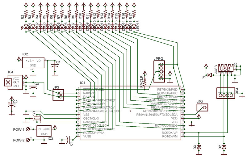
FIGURE 1. EAGLE schematic.
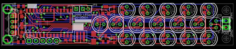
FIGURE 2. Layout.
Design Rules
I’ve created rules for my circuit design that save money and time, and use resources wisely:
- Use parts that I have tested and that I know function properly.
- Whenever possible, use parts that I already have.
- Add extra parts or tasks (e.g., pads, test points, etc.) in a logical way that allows for future variations. I’ve found that when I spend time to design and test something, I get to know the design very well. So, why create something new when I can build on something that I am already comfortable with?
- Save money whenever possible. Being frugal without sacrificing quality makes sense to me and saves dollars for my clients.
When soldering SMT components, don't worry so much about seeing 100% of the soldering scene. Rely on the fact that a good solder joint flows in a particular way that changes how light is reflected. Learn this art and it will make SMT soldering just a bit easier.
Hardware
Starting at the far left of the layout and moving to the right, I’ll explain the rationale behind some of the parts you see in the following figures.
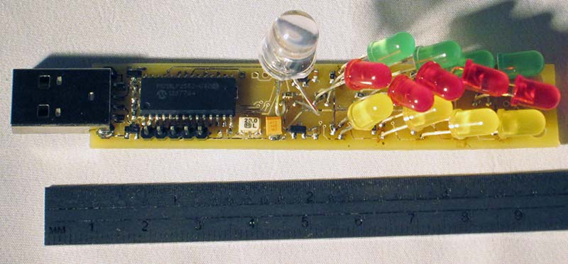
FIGURE 3. The original work-in-progress prototype. (Boy, is it messy!)
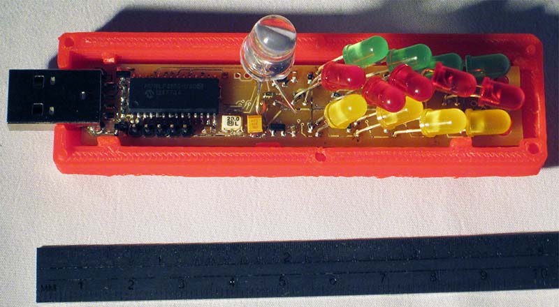
FIGURE 3A. Prototype in plastic enclosure
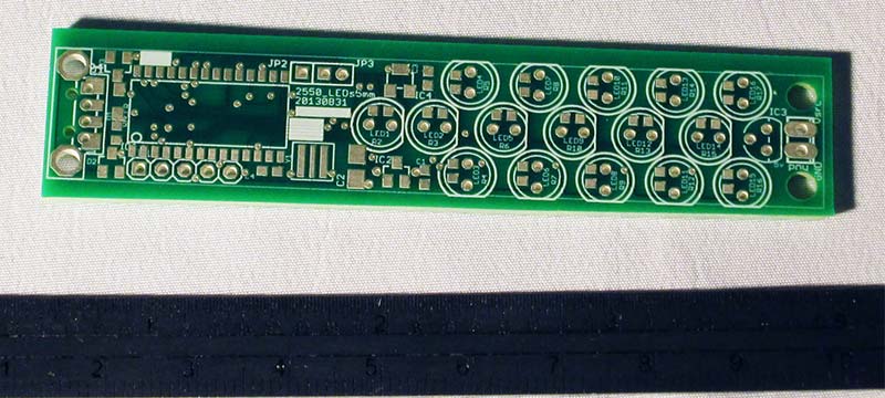
FIGURE 4. The unpopulated production-quality PCB.
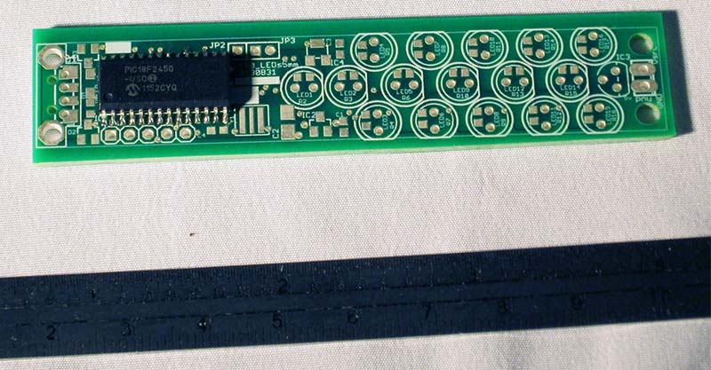
FIGURE 5. First step of PCB assembly; Microchip PIC installed.
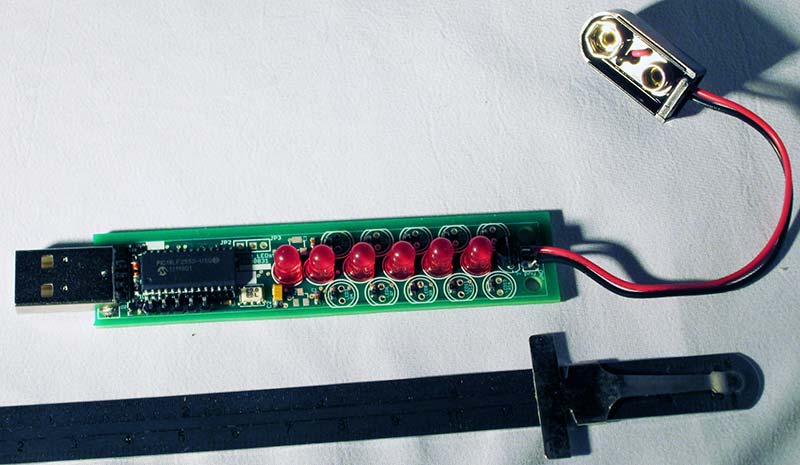
FIGURE 6. PIC support components and center LEDs added.
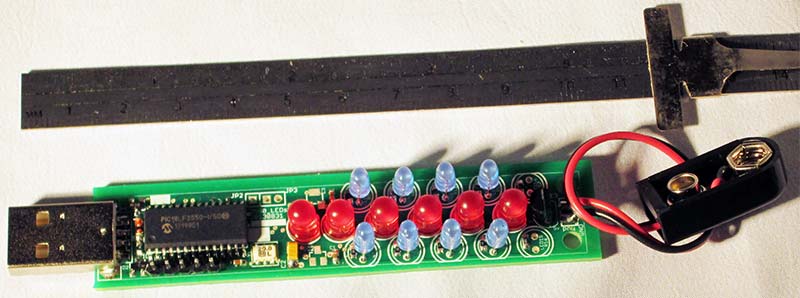
FIGURE 7. PCB side LEDs finish the assembly.
The USB connector (JUSB) is a surface-mount part that has four vias that overlap the SMT pads. That violates a design rule! I added holes so the modified design could use several of the SMT products available for Type-A connectors, as well as some of the through-hole versions. This allows the design to use a wide range of vendor parts for the USB connector. If you have ever tried to source these, you know how much of a variation in price there can be.
There is nothing apparent in the layout design for the Microchip PIC (IC1) that might seem to allow us to use a wider range of these particular microcontrollers, but there is. The original design was for the PIC18(L)F2550 which has 32K of programming space. The PIC18(L)F2450 part has the same footprint with 16K of program space. There are some savings there if your program doesn’t need all that.
Since these USB-enabled parts were released, there are newer drop-in replacement parts available that do not need external clocks (Y1) to function. Namely, these would be the ‘K’ series parts from Microchip. The ‘J’ series parts can work, but this design does not provide for an extra capacitor or voltage source that this series would need. I didn’t overlook these; I just didn’t plan on using them in this design. Besides, the PIC18F25K50 part is plenty cheaper than the original 2550 part.
Remember: The part documentation states that the PIC18LF25K50 does not have a built-in regulator to power the USB connection; however, the PIC18F25K50 does. This circuit design only supports the internal USB regulator parts.
There is no reason to waste space using 5 mm through-hole LEDs when SMT LEDs take up considerably less space. (Refer to the self-imposed design rules.) There are several factors to consider here:
- 5 mm LEDs are cheap and plentiful. You can find them in many surplus shops.
- 3 mm LEDs fit too.
- Since they are through-hole, we can place the LEDs on top or even on pigtails if needed. There are many options.
- For most, the SMT parts are not as easy to change out should they stop working or if you simply want a different color LED in that particular location.
- Through-hole parts have added mechanical strength because of how they are mounted on the PCB (printed circuit board). SMT parts assume and provide very little mechanical resistance.
The final items to consider are the voltage regulator (IC3) and its jumper (POW). The previous USB keyboard design had these items too, but they were rarely needed. That PCB didn’t drive any loads by design; it only needed enough current to power the PIC and some switches. The power provided by the USB connection is just fine for that. This design has a bunch of LEDs and those can draw a lot of current depending on the design.
Additionally, this PCB is much more useful than the keyboard design as a stand-alone PCB. The 5 VDC regulator allows for an alternate external power source to be connected so that the PCB can function without a PC.
Speaking of LED current, keep in mind that PICs are typically designed to source only about 10 mA and sink about 20 mA of current. That is why all the LEDs use negative logic (a digital 0, 0VDC) to turn on the individual LEDs. This allows the PIC’s internal transistors to be used in their most current-efficient configuration. However, this does not mean that the PIC will like driving all the LEDs at full current for very long without getting hot. Of course, this doesn’t mean that it cannot. It just means that either we design or program to limit the illumination time of all the LEDs, or we add a heatsink and fan.
Make surface tension your friend when working with SMT. Expect small parts to move and learn to use this to your benefit, not to your frustration.
I assigned the LED series resistor a value that is slightly higher than it needs to be in order to drop the effective current a bit. If you do the math — assuming a 5 VDC source — typically, you would need about a 100 ohm resistor for each LED. In practice, any resistor value from 100 ohms to 1K ohm will work without much reduction in LED brightness.
I tend to starve LEDs of current in most designs that use them as simple event indicators. I would probably use a 3K ohm resistor which I also used on the previous keyboard circuit. This time, we probably want the LEDs to be bright. You can adjust these values as you see fit. As long as you can see the LED and don’t make the PIC sink too much current, everything should be fine.
This design will not populate LED15 and LED16. If they are connected and you hook up an in-circuit programmer to the program jumper (JPRG) and try to program, those LEDs will demand more current than most in-circuit programmers can handle, thereby ruining most programmers.
Make sure you remove the LEDs before you program. Another option: Use a 10K ohm resistor to connect the two LEDs. Doing so usually reduces the current sufficiently to allow the in-circuit programmers to function. If you choose not to remove the LEDs before you program, they will function but will be noticeably dimmer than the others.
Firmware
That should cover all of the physical aspects of this circuit. Let’s move on to the firmware. The firmware is quite basic, as is pretty much always the case with good code. The firmware does not follow any formalistic standards. It was written as each part of the functionality was added in order to keep variables and the logical flow easy to understand. Clean code is the best thing that one programmer can give to another programmer.
I do not claim that this is the best code in the world. In fact, it is what I generally call “quick and dirty code” or “Get-R-Done” code (spoken in the voice of Larry, the Cable Guy, of course).
The firmware is divided into three basic sections, listed from the beginning of the file “2550USBLEDs_20121020.c:”
- Global device definitions
- Support functions
- The main function
The first two sections are not useful in the context of this article. The main routine contains all of our upper functionality. It starts out initializing the device by configuring ports, the analog-to-digital converters (ADCs), turning off the LEDs, initializing the USB connection subsystem, and waiting a moment or two. It’s not the best code, but it works. You must respond to any new USB connections within the spec time. That is why the usb_task() function is called from time to time within all of the code.
That brings us to the main while loop. By way of a verbal block diagram, the first 10 or so lines are the repeated housekeeping activities — like allowing the USB functionality time to work, blinking an LED to show that we are alive, and clearing out the LEDs after extended periods of non-activity.
Next, we get our temperature data or our Hall magnetic data based on what mode the device is running in. There are four modes defined so far:
- DISP_MODE_NONE: Does nothing unless commanded via the USB port.
- DISP_MODE_RANDOM: Randomly sets the LEDs on or off.
- DISP_MODE_TEMPDATA: Sets the LED output based on the present temperature value acquired.
- DISP_MODE_HALLDATA: Sets the LED output based on the present Hall value acquired.
The last longwinded section of the main function handles the incoming USB commands. This section requires far more code than displaying and acquiring the sensor data does. However, it is no more complex. Its only functions are making sure there is a connection to the USB and there is data waiting on the line, as well as seeing if any of the incoming data matches one of our supported commands.
The commands are pretty simple. The important ones turn the individual LEDs (A-P and a-p commands) on and off, set the modes mentioned previously (W-Z commands), and produce a help screen (‘?’ command). That’s the main function and its infinite while loop.
The support functions called by the main loop are pretty straightforward. They validate data, perform some calculations, and either return some data or turn LEDs on or off. Don’t get me wrong; I am not over-simplifying things. We are all hobbyists here, so I don’t want to over-explain that which is obvious.
As presented, this design requires a driver file to be loaded on a PC. The driver files (provided by CCS, Inc.; www.ccsinfo.com) produce the compile with which this project was built. The PIC can be programmed to use any driver that you write your own code to utilize. So, technically, you are not limited at all. However, if you want to use the design as-is, you must use the drivers provided, as well as those that are available for download.
I will make a firmware version that also allows the use of the HID interface. These types of devices generally do not require additional drivers. In my previous article, I described what might need to be done if you use a really old PC.
Troubleshooting
As for troubleshooting, most — if any — issues will concern getting the PC drivers to install correctly. Once that is done, if the device responds to commands issued via a communications port connection (via the virtual USB-to-serial drivers), that is a good sign the device is powered and mostly working. If the LEDs do not illuminate or sensors do not return data, uninstall and reinstall them.
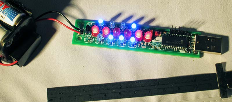
FIGURE 8. Initial LED test in random mode.
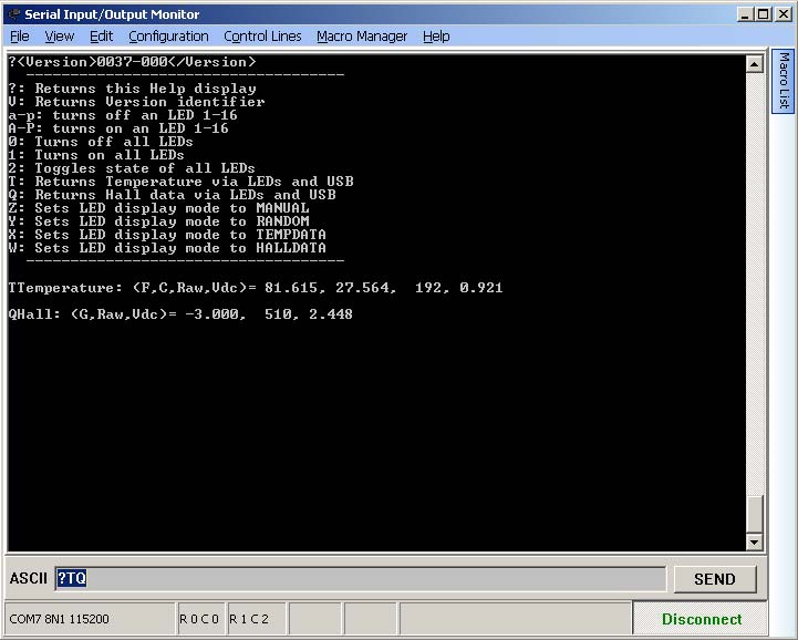
FIGURE 9. The serial port output.
On the off chance that a component is bad, replace it. If you cannot get the device to connect via USB and the drivers have been installed, make sure that diode D1 is installed correctly. If it is backwards, the device will not work via the USB power connection alone. If you have diode D1 installed backwards and have an external power supply connected, it would still work, and the USB connection would be active.
However, in this scenario, you would be supplying five volts DC to the PC’s USB data link. In most cases, nothing would happen, but many laptops only provide 3 VDC on their USB devices. In this case, you would probably damage the USB port. Needless to say, I recommend installing diode DI correctly.
I hope this design is simple and straightforward enough to be helpful. I further hope that the logic and rationale used were more beneficial than the core functionality of the design. The physical design is quite simple, but the firmware can make this little circuit do a lot of useful things. Once you add a PC to the USB connection, who knows what a little imagination can bring!
Remember, there is a lot more that you can do with this simple circuit. As long as you stay within general safety and device limitations, you should be just fine. NV
I designed a simple enclosure for this project. It’s nothing fancy, and you will have to trim it to fit because I made the design quite tight in order to ensure a snug fit. I uploaded the project files for those who have access to a 3D printer. The files are at www.thingiverse.com/thing:157512. Also, the examples of using this PCB to illuminate translucent 3D prints are courtesy of the thingiverse.com shares, as well.
PARTS LIST
| ITEM |
VALUE |
DEVICE |
NOTES |
| C1,C3 |
0.1 µF |
CAP 0603 |
Noise reduction |
| C2 |
4.7 µF |
CAPPOL 3216-18W |
Current boost for LEDs |
| C4 |
0.47 µF |
CAP 0603 |
Required for USB communications |
| D1 |
1N4148 |
DIODE-SOD323-W |
USB power protection diode |
| D2,D3 |
3.9V |
ZENER DIODE SOT23 |
USB data line protection |
| IC1 |
PIC18F2550_28W |
PIC18F2550 |
Main control IC; can substitute PIC18LF2550, PIC18(L)F2450, PIC18F25K50, or PIC18F24K50 |
| IC2 |
LM50 |
LM50 |
Analog output temperature IC |
| IC3 |
LP2950ACZ-5.0 |
LP2950ACZ-5.0 |
5 VDC regulator |
| IC4 |
A1301LH |
A1301LH |
Analog output Hall sensor |
| JP2 |
DNP |
PINHEADER 1X01 |
Test/AUX point |
| JP3 |
DNP |
PINHEADER 1X02 |
Test/AUX point |
| JP4 |
DNP |
PINHEADER 1X04 |
USB optional through-holes |
| JPRG |
|
PIN HEADER 1X05 |
*To allow in-circuit programming |
| JUSB |
|
CON-USB_A_SMD |
|
| LED1-16 |
|
Any color 5 mm LED |
|
| POW |
DNP |
MPT2 |
Battery Connection |
| R2-R15 |
100 ohms to 1K ohm |
RES 0603 |
|
| R16-R17 |
10K ohm |
RES 0603 |
*To allow in-circuit programming |
| RMCLR |
39K |
RES 0603 |
|
| Y1 |
20 MHz |
Ceramic resonator |
|