As electronic experimenters, we all build a variety of circuits and gadgets. That means we usually have to test and troubleshoot these projects. The main instrument we use for this is the digital multimeter (DMM). It can measure voltage, current, and resistance. Some DMMs even measure capacitance and transistor gain. Yet this capability is often not enough. What we really need is an oscilloscope so we can see the signals in our circuits. A scope is particularly helpful when we are using high frequency digital logic, microcontrollers, and RF ICs.
But that’s not all. Some projects require a signal generator. Wouldn’t it be great to have a logic analyzer? How about a spectrum analyzer? Dream on. If you are a serious enough experimenter, you may already have a scope and some other test gear. Many of you are serious experimenters but don’t have a big enough budget for a scope, much less project parts or other test gear. There is a solution for this that you may not have thought of: virtual instruments (VIs). For just a few hundred dollars, you can have a whole bench full of high quality test instruments of the VI type.
What is a Virtual Instrument?
A VI is a software-based instrument that uses a PC desktop or laptop for its processor and screen. The VI hardware for a scope is a small box with a fast analog-to-digital converter (ADC) that is used to digitize the signal to be observed. The ADC samples the input signal and stores the digital samples in memory. Special software then uses these samples to reconstruct the signal for display on the video monitor or LCD screen. The software also formats the screen to look like a typical scope display with its measurement graticule, and implements controls to vary horizontal sweep timing, triggering, and amplitude adjustment. It is also possible to implement dual or four channels of input for concurrent display.
To implement a signal or function generator, the software stores digital samples of desired output waveforms like sine, square, or triangle waves. These samples are fed to a digital-to-analog converter (DAC) that generates the analog output signal. The software also provides a screen showing the output as well as the controls for output frequency and amplitude. Some VIs incorporate an arbitrary waveform generator (AWG) that lets you create special output waveforms that you may need for testing.
Other VIs are also possible. A popular one is a spectrum analyzer that shows signal power plotted over frequency. Commercial spectrum analyzers cost thousands of dollars. A VI spectrum analyzer takes the input signal digital samples and uses a mathematical algorithm called the fast Fourier transform (FFT) to generate the displayed signal in the frequency domain. The PC does all of the heavy computing required by the FFT software.
The VI idea was pioneered by National Instruments (NI) who created the well-know VI software called LabVIEW. It was used on the early Apple Macintosh computers to work with NI’s data acquisition products. Today, most modern test instruments are essentially software based with built-in displays. However, you can also buy a cheap VI in a small box to use with your PC to produce several very useful test instruments. The rest of this story gives some examples.
The Analog Discovery 2
The Analog Discovery 2 is a full blown VI in a small box as shown in Figure 1. It is made by Digilent, Inc., which is a company that is owned by National Instruments.
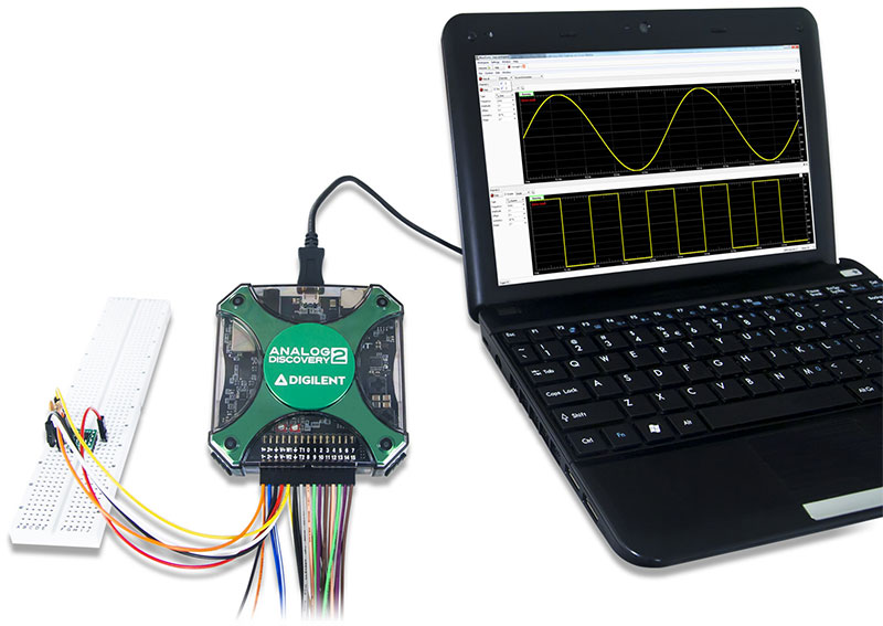
FIGURE 1. Digilent’s Analog Discovery 2 virtual instrument package. Connect it to a laptop via a USB cable and you have a full work bench of test equipment.
All of the ADCs, DACs, and other circuits are in the small enclosure. The whole thing is powered by the +5 volts from the USB connection to the laptop. The VI software that creates all the instruments is called Waveforms and is installed on the laptop. The software runs under Windows, Apple Mac OS, or Linux. The colored wires are all of the inputs and outputs (I/O) that connect to external circuitry. This photo shows the outputs from two function generators displayed on the dual trace oscilloscope. Special pins are used with the I/O leads to connect to the circuits on the breadboarding socket.
The amazing thing is what the Discovery 2 implements. Take a look at what’s inside the box:
- Two-channel USB digital oscilloscope (1MΩ, ±25V, differential, 14-bit, 100 Msample/sec, 30 MHz+ bandwidth — with the Analog Discovery BNC Adapter Board)
- Two-channel arbitrary function generator (±5V, 14-bit, 100 Msample/sec, 20 MHz+ bandwidth — with the Analog Discovery BNC Adapter Board)
- Stereo audio amplifier to drive external headphones or speakers with replicated AWG signals
- 16-channel digital logic analyzer (3.3V CMOS, 100 Msample/sec)
- 16-channel pattern generator (3.3V CMOS, 100 Msample/sec)
- 16-channel virtual digital I/O including buttons, switches, and LEDs — perfect for logic training applications
- Two input/output digital trigger signals for linking multiple instruments (3.3V CMOS)
- Single-channel voltmeter (AC, DC, ±25V)
- Network analyzer — Bode, Nyquist, Nichols transfer diagrams of a circuit. Range: 1 Hz to 10 MHz
- Spectrum Analyzer — power spectrum and spectral measurements (noise floor, SFDR, SNR, THD, etc.)
- Digital bus analyzers (SPI, I²C, UART, Parallel)
- Two programmable power supplies (0 to 5V, 0 to -5V). The maximum available output current and power depend on the Analog Discovery 2 powering choice:
- 250 mW max for each supply or 500 mW total when powered through USB
- 700 mA max or 2.1W max for each supply when using an external wall power supply
It literarily is a whole test bench of instruments that you usually need when experimenting, designing, troubleshooting, or otherwise playing around with circuits or equipment. Individual test instruments with these specs would cost you thousands of dollars. Save up. It is worth it.
A lower cost version called the Analog Discovery is also available. The scope and AWG bandwidths are only 5 MHz, and the power supply current capability is more limited to 50 mA. This will restrict your range of applications. I also recommend their BNC connector adapter board that lets you use standard scope probes that will give you the full 30 MHz bandwidth. They also have a wall wart transformer power supply if your power supply needs exceed the capability of the USB port.
Another Option
There are other similar products on the market. A couple of years ago NI introduced their myDAQ product (see Figure 2). This device uses a reduced version of LabVIEW software to implement the instruments.
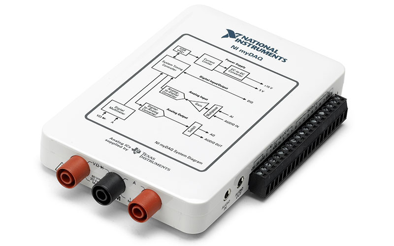
FIGURE 2. National Instruments’ myDAQ virtual instrument and educational trainer. It is widely used in colleges and universities giving students a portable lab.
NI myDAQ includes two analog inputs and two analog outputs at 200 kS/s and 16 bits, allowing for applications such as sampling an audio signal. It also has eight digital inputs and output lines; +5, +15, and -15 volt power supplies; and a 60V DMM to measure voltage, current, and resistance. The myDAQ connects to the PC via a USB cable. Connections to the circuits under test are by way of screw terminals. The primary limitation of the myDAQ is its limited scope and generator bandwidths making it suitable only for audio frequency range signals or just above.
The myDAQ is widely used by students in colleges and universities who can run their lab experiments and exercises in their dorm room or at home instead of the college lab. A considerable amount of lab manuals and other courseware has been developed around the myDAQ.
Just the Oscilloscope
There are also products that just implement the scope rather than the full instrument package. A good example is Velleman’s two-channel USB oscilloscope; refer to Figure 3. Velleman for Makers is now called Whadda, the new Premium Maker Brand by Velleman.
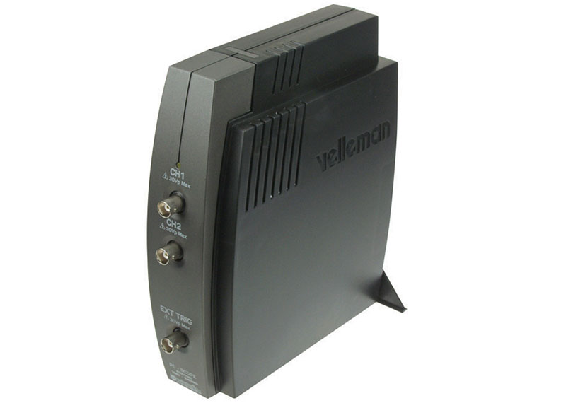
FIGURE 3. The Velleman/Whadda PCSU1000 is a two-channel virtual oscilloscope with a 60 MHz bandwidth. It includes a spectrum analyzer function.
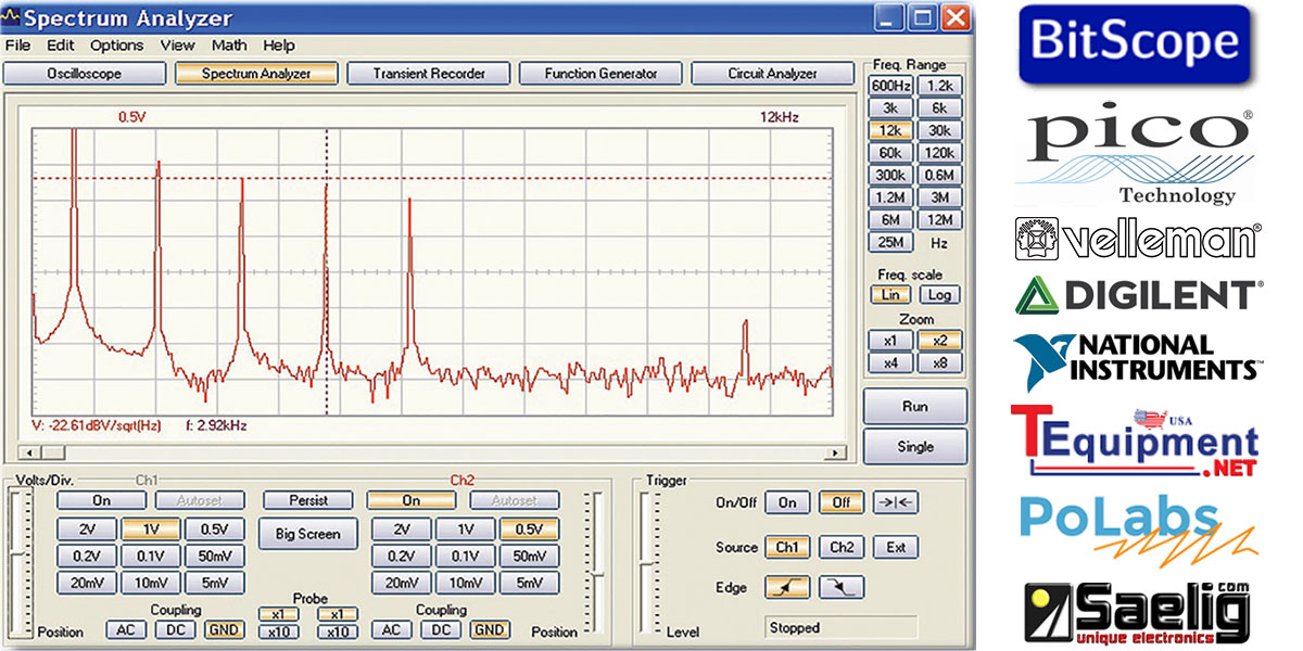
The sampling rate is 1 Gb/s and the bandwidth for each channel is 60 MHz. The PCSU1000 also includes a spectrum analyzer function. Figure 4 shows a screenshot of the scope doing an FFT that produces the spectrum display. It can handle input signals in the 1.2 kHz to 25 MHz range.
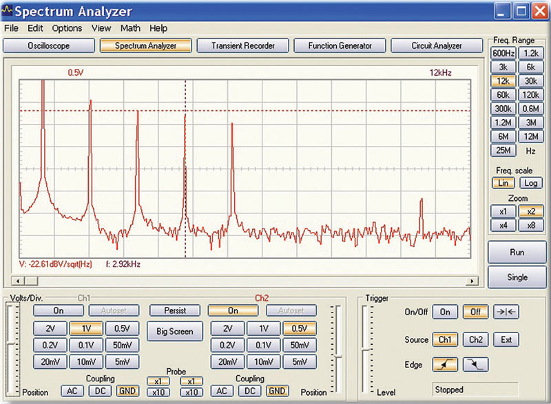
FIGURE 4. Screenshot of the spectrum analyzer feature on the Velleman PCSU1000 scope.
Velleman also makes the lower priced PCSU200: a dual channel scope with a function generator. It has scope input bandwidths of 12 MHz. A spectrum analyzer function good to 12 MHz is also included. The function generator produces sine and square waves from 0.5 Hz to 500 kHz (or 1 MHz for the sine).
Another scope supplier is PicoTech. Their PicoScope product line is extensive. They offer dozens of models that range in price from a few hundred dollars to thousands of dollars. Bandwidths vary from 10 MHz to 20 GHz. Most models have a built-in AWG.
Next time you are ready to spend on your experimentation, consider one of these items that will greatly expand your scope and capabilities. NV