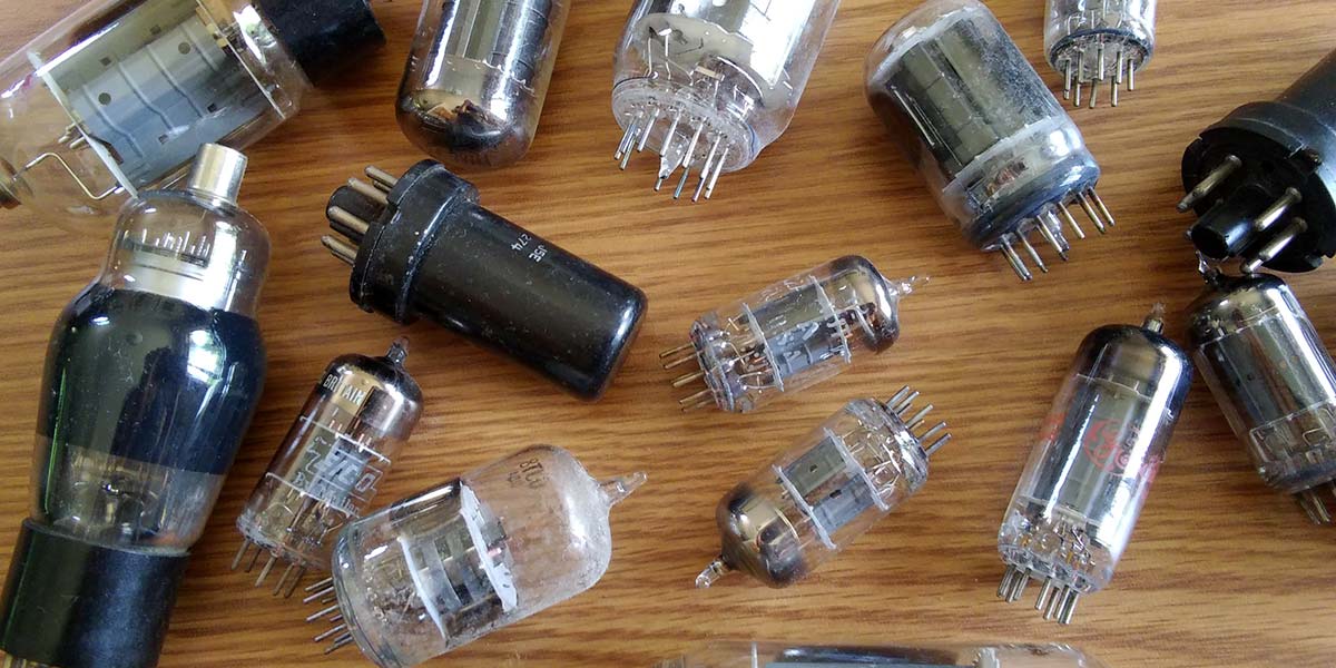
Electronics hobbyists have always designed circuits and built devices. When electronics was in its infancy, this was out of necessity. As the technology has advanced and gotten smaller, we’ve continued to construct electronic devices. Among the technologies available to us are vacuum tubes, invented over 100 years ago and dominant until the rise of semiconductors. They’re still interesting, rewarding, and worthy of investigation.
Why Build with Tubes?
There are a number of reasons to pursue tube-based projects. Vacuum tube technology is accessible; the principles on which tubes operate are straightforward. Tube circuits generally require a reasonable number of other parts.
It’s rewarding to operate devices whose functioning we completely understand and that we can maintain and repair.
Building with tubes reviews the history of the technology and promotes an understanding and appreciation of its development. If you are of a certain age, you can revisit projects you began many years ago. We can obtain interesting and useful functionality from tube circuits. Plus, tubes generate that pleasant orange glow.
Figure 1 shows three homebrew tube projects.
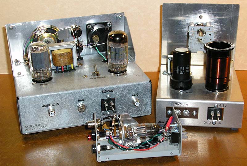
FIGURE 1. Three homebrew tube projects: a receiver back end (beat frequency oscillator, product detector, and audio output stage); a one-tube regenerative receiver; and a test oscillator.
Finding Information
The Internet has made it easy to find information about vacuum tube technology (and just about everything else; some of it is even accurate). Google and a grain of salt are your friends.
There are many websites — too many to list here — devoted to tube datasheets, principles, circuits, and projects. Electronics and amateur radio magazines from the ‘50s and ‘60s — Popular Electronics, QST, CQ, 73, Ham Radio, and others — are extremely informative. Most of these are archived on-line or on CD; you don’t need to locate physical copies.
Similarly, you can download books from that period: RCA tube manuals, textbooks, and instruction manuals; The Radio Amateur’s Handbook (yearly editions); and many more. Currently, the magazine Electric Radio (ermag.com) presents tube-based radios and related projects (see Figure 2).
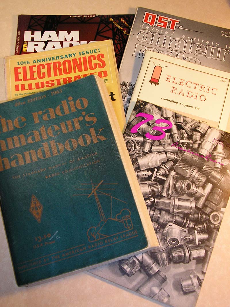
FIGURE 2. Some books and magazines from the 1960s that describe tube-based projects.
Getting Started
To begin, survey online sources and do some background reading; the more you know, the better. Start with small projects. Reproducing published examples provides experience, but don’t be afraid to experiment. In comparison to semiconductors, tubes are forgiving and can be (briefly) abused without ill effects.
Unless you’re reproducing a project from a magazine or book, it’s helpful to implement each circuit on a breadboard before constructing a permanent version. You want to be able to fiddle and adjust easily. There are more ways to breadboard tube circuits than can be presented here. Again, online searches will lead you to them.
Tube construction is generally chassis and panel as you would find in, say, a short-wave radio from 1965. So, permanent versions of projects generally require some metalwork. You can develop experience by building small modules that implement useful circuits like power supplies, audio amplifiers, and functional parts of receivers. A classic beginning project is a simple regenerative receiver.
You can also restore old hardware to useful function. For a good example, see the recent article in Issue-3 2020 by Bryan Bergeron in which he describes restoring a ‘60s-vintage AM/FM table radio.
Finding Parts and Materials
Tube circuits require many of the same parts as semiconductor projects: capacitors, resistors, connectors, and so on. The more difficult parts to find (and afford) are variable capacitors, filter chokes, and transformers. The latter include power transformers, intermediate frequency transformers, and audio interstage and output transformers. Hardware is mostly the same as for semiconductor projects, but tube sockets and terminal strips may be harder to find. Figure 3 shows examples of these parts.
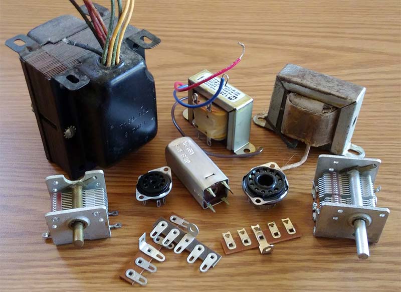
FIGURE 3. Parts for tube circuits that can be harder to find: variable capacitors, filter chokes, transformers, tube sockets, and terminal strips.
There are many sources — some more economical than others — for parts. Hamfests are flea markets for amateur radio operators and other electronics enthusiasts. They offer wide varieties of radios, tubes, other parts, and magazines and books (as well as interesting conversation) often at remarkably low prices. Due to COVID-19, no hamfests are happening as of this writing, but they should return soon. Figure 4 was taken at a hamfest in 2019.
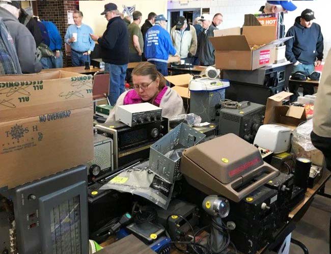
FIGURE 4. A table and the crowd at the the St. Cloud (MN) Amateur Radio Club hamfest.
Metal chassis are still available. We can repurpose salvaged chassis and enclosures, and we can build our own. For sheet stock, look through the drops (cut-offs) at a retail sheet metal supplier. Aluminum is your best bet.
Salvaging old hardware is not as productive as it once was, but you may run across an old TV, table radio, or “hi-fi.” The most useful parts in these units — after all these years — are probably transformers and variable capacitors. (In the 1960s, Doug DeMaw W1FB described in QST a number of novice projects built entirely with parts extracted from dead TVs.) Don’t disassemble any unit for parts with historical value.
In addition to the RadioShack aisle in HobbyTown, there are other retail outlets. In particular, look for commercial and industrial surplus stores which may have large and affordable stocks of tubes, transformers, and related parts.
Of course, the Internet provides many mail order outlets, some specialized and some more general like eBay and Amazon. Tube types favored by audiophiles and guitar players — for example, 12AX7, 6V6, and 6L6 — are generally expensive. Less well-known types will be much cheaper.
For example, Compactrons are 12-pin envelopes developed for TV applications. They contain up to four individual units that are often electronically identical to various miniature types. Compactrons are plentiful and inexpensive. In any case, there are many alternatives; tubes should be cheap.
Tools and Test Equipment
The tools required for tube-based projects are mostly the same as those for any electronic building. Hand tools include screwdrivers, soldering irons, pliers, diagonal cutters, files, and so on. Tube sockets mount in circular holes, so some way to cut them is necessary. Chassis punches are nice, but expensive; circle cutters and step bits are good options.
An electric drill with a good selection of bits is essential. If you can afford one, a drill press is better. Other larger metalworking tools might include a bending brake (a small one should be inexpensive) and, if possible, a metal shear for cutting sheet stock (much more expensive). You may have access to a shop in which metalwork can be carried out. Consider makerspaces which exist in many communities and schools.
Test equipment for building with tubes is the same as for building with semiconductors. The most important item is a multimeter, either analog or digital. Also useful are an adjustable metered power supply (high voltage in this case, and you should build it yourself) and audio- and radio-frequency signal generators. An oscilloscope is useful but more expensive; consider a used one at a hamfest. Another option is a PC-based ‘scope front end, though these have lower maximum frequencies. Figure 5 shows a typical selection of test equipment.
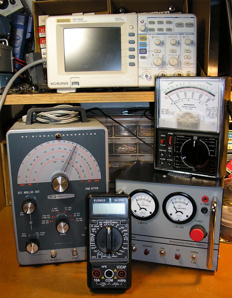
FIGURE 5. Test equipment for building with tubes. Clockwise from the top: oscilloscope, analog multimeter, power supply, digital multimeter, and RF signal generator.
Notes
Throughout the process of designing, debugging, and building projects, keep notes that describe what you’ve done, how it worked, what you changed, steps of construction, and so on. These notes are your record of each project. You may think you’ll remember everything you’ve done and why, but over a few weeks or months it can all become a mystery.
You have a free hand in how you maintain your notes. The two obvious options are on paper or in a computer file. In either case, record more detail than you think is necessary, include schematics and pictures, and update your notes regularly and often. (This requires discipline; ask me how I know.)
Keep track of the sources of information — book pages, magazine articles, web pages, and file names — and review your notes from time to time. They may remind you of unfinished projects or inspire new ideas. Throughout, remember that you’re writing for yourself and not an external audience, so neatness counts, but only as much as you want it to.
I keep my notes in hardbound sketchbooks. Figure 6 shows a small project on the pages that describe it.
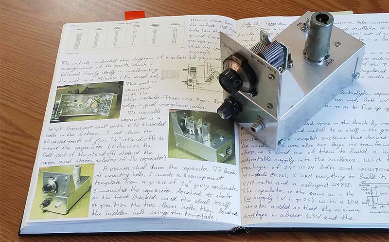
FIGURE 6. A tube project and the pages of notes that describe its development.
Caution – High Voltage
Remember that tubes require higher voltages than semiconductor circuits do, so be careful. Connect bleeder resistors across all power supply filter capacitors. Be aware of when a breadboard or device is on.
When a device is on, keep one hand in a pocket and allow no one else close to the work. Watch out for pets. Turn everything off when you step away.
A First Project
A good place to begin is a small power supply to provide some of that dangerous high voltage. At its heart will be a transformer with a 120V primary winding and two secondaries: 6.3V for tube filaments and a higher voltage from which to derive a tube’s B+. Depending on the secondary voltage and whether the secondary winding has a center tap, rectification may be half wave or full wave.
A useful extension to such a circuit is metering of both the output voltage and the current drawn from the supply. A further extension regulates the output voltage and allows it to be varied. Figure 7 shows a supply with these features. I described this unit here a couple of years ago (Issue-5 2019). Many other examples appear in print and on-line.
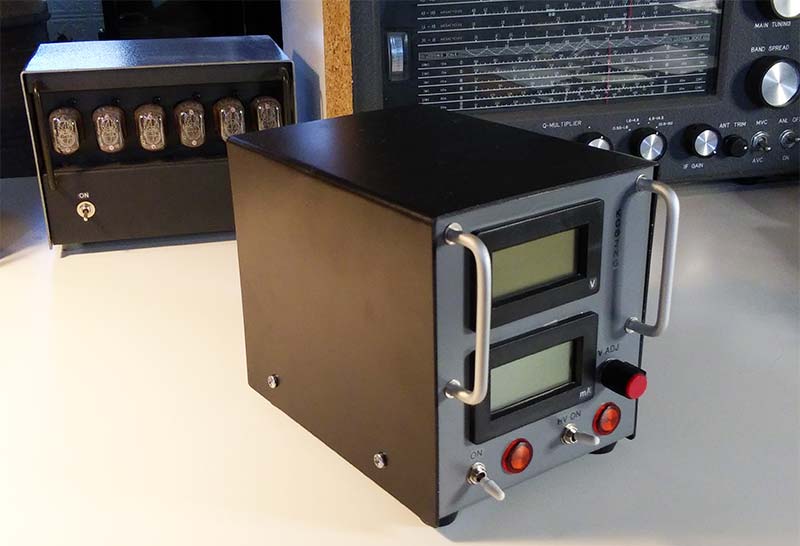
FIGURE 7. A power supply for tube projects. It provides 6.3 VAC for filaments and adjustable, regulated, metered high voltage for B+.
A Few More Suggestions
To keep the process of building a project moving forward, accumulate or have access to the necessary parts and tools. Be reluctant to throw anything away — especially hardware. You may think you’ll never need that triangle of aluminum with the right-angle bend and threaded 4-40 hole, until you do.
If possible, make your workspace larger than you think it needs to be; it will fill up soon enough. Keep small parts organized. It’s frustrating to look through boxes and cans for a 150K 1/2W resistor that you know you have a bunch of.
As mentioned earlier, start with small projects and work up. Most important, have fun. NV
How Triodes Work
Vacuum tubes began with the invention of the light bulb: a glowing filament in a vacuum. This was followed by the observation that a bulb’s heated filament gives off electrons. If the filament is connected to the negative terminal of a battery (in addition to the voltage that lights it up) and a second electrode is introduced and connected to the battery’s positive terminal, electrons flow from the filament through the vacuum to that second terminal. This is called the Edison Effect, and the resulting structure is a diode.
In a diode, the heated filament is the cathode and the positively charged electrode is the anode or plate. The introduction of a third electrode — a grid — between the cathode and the anode yields a triode. The grid is wound of wire, so electrons can pass through it to the anode. The voltage on the grid controls the flow of electrons from the cathode to the anode. A small change in that voltage produces a larger change in the electron flow. Thus, a triode can amplify a signal.
In recent tubes, the filament and the cathode are separated. The filament heats the cathode which emits electrons. Figure A shows the usual schematic symbol for a triode.
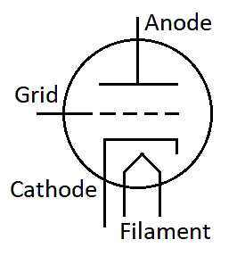
FIGURE A. Schematic of a triode.
The voltage required to light a tube’s filament is generally modest — a common value is 6.3V — but the voltage applied to the anode is usually above +100V, and for a receiving tube may be as high as +250V. For high-power transmitting tubes, the voltage applied to the anode can be much higher still.
Schematics represent a triode’s cathode and anode with straight lines and grids with dotted lines. In physical tubes, however, the electrodes are generally concentric circles from the filament out.
More grids can be added to refine a tube’s performance. A screen grid between the original grid — now the control grid — and the anode receives a positive charge and draws electrons through the control grid. A suppressor grid following the screen grid is often connected to the cathode and, with its relative negative charge, prevents electrons from bouncing off the anode.
The name of a receiving tube is generally a number that indicates its filament voltage (one or two letters) and another number that indicates the number of elements in the envelope. A 6C4 triode, for example, requires 6.3V on its filament and consists of four electrodes: filament, cathode, control grid, and anode.