Use an Arduino to Show “Filament Remaining” Readouts
About a year ago, I bought a 3D printer DIY kit, and overall, it has been a fun addition to my shop. Once I got the printer tuned up and running well, I was able to design and print quite a few items. It’s really neat to watch the layers stack up into a finished object!
As you might expect, 3D printing can take a while. In fact, print times vary greatly, ranging from a few minutes for small simple objects, on up to multiple days to print large complex objects. While it’s always a good idea to watch the first few layers go down, most of a 3D print job can be achieved in a “lights out” unsupervised fashion.
All 3D printers monitor and control key operating parameters throughout the print process. Unfortunately, when a problem is encountered, most aborted or incomplete printed jobs must be tossed out, the printer bed cleaned up, and the job restarted from the beginning. While machine faults can occur, operator-preventable errors such as filament runouts can also be a frustrating cause of a print failure.
Be sure you have enough filament!
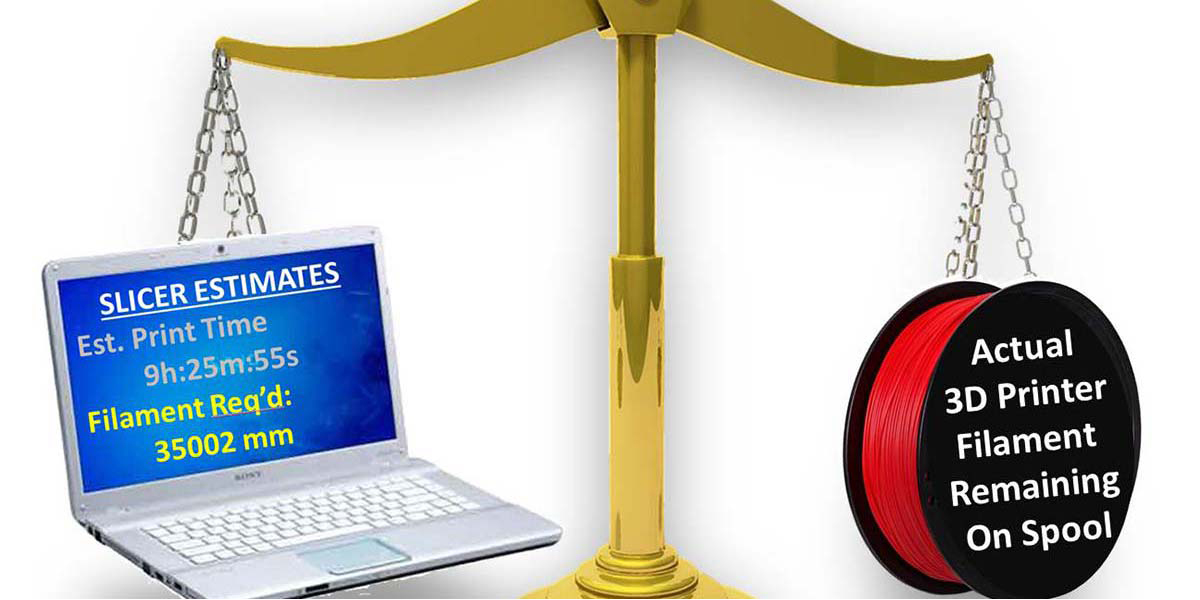
One thing you want to check before you start a long print job is to verify you have enough filament on the spool to complete the print! You don’t want to come back to your printer at the end of a two-day print (as I have!) only to discover that the machine ran out of filament and the top 1/4 inch of the object is missing! While the cost of the lost filament is problematic, the lost print time is even more frustrating — especially if you’re anxious to get at the finished part. So, before starting a complex multi-hour/multi-day print job, you want to be sure that your printer has enough filament to complete the task.
A fresh spool of filament holds 1 kg (2.2 lbs) of raw material. That’s a lot and will typically support many days of continuous print time. Even though the slicer program dutifully predicts print time and filament needed (Figure 1), I’m usually left looking at the filament spool wondering “Exactly how much filament is left on that spool? Will it be enough? Am I feeling lucky today?”
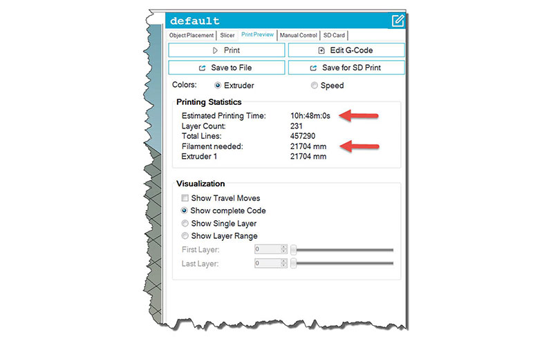
FIGURE 1. The slicer program predicts print time and material usage.
Weight-to-Length Conversion
To reach a more definitive answer, one can simply weigh the filament spool and subtract the weight of the empty spool itself to get to just the remaining filament weight. With the filament weight in hand, you can convert the filament weight to filament length as follows:
Length_Remaining = Filament_Weight / (Filament_Cross_Section_Area x Filament_Density)
As shown, a postal scale can be used to measure the filament weight — don’t forget to subtract the empty spool weight! The filament cross section area (π x r2) is easily calculated since we know the filament diameter; usually 1.75 mm or 3.0 mm. Lastly, the filament density is a constant that we can get from the specs provided by the filament supplier/manufacturer.
Once we’ve converted our data into to a remaining length value, it’s only necessary to compare that value to the slicer “Filament needed” number (Figure 1) to know when a spool change is prudent.
If you have a small scale, the example demonstrated in Figure 2 will get you started. You may find that is all you need! Just be sure that when making your calculations, be mindful to manage all the units (i.e., grams/cm3, cm, mm, etc.) properly so that you come out with a valid length value (usually in meters or millimeters).
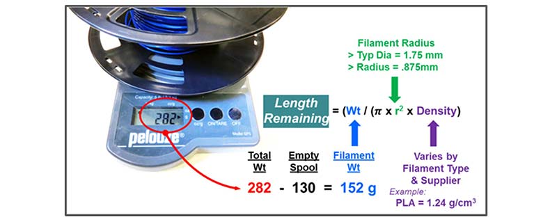
FIGURE 2. Using a postal scale to help derive the length remaining.
As a reference point, a full 1 kg spool of 1.75 mm diameter PLA filament should come out to be close to 340 meters (340,000 mm).
Can we do better? Yes! With an Integrated Spool Scale Solution
After using my postal scale and manually calculating remaining length values for a while, I wondered if there might be a more complete and easy-to-use method available. While a search of the Internet identified a lot of information about measuring weight using strain gauge load cell beams, I couldn’t find a fully implemented “spool scale” solution. So, I decided to give it a try. This project describes a dedicated spool scale that provides a real time readout for the filament length remaining.
First off, I located a low cost ($6) strain gauge load cell beam with an I2C interface on eBay. I bought one and found it to be small enough to fit inside of a filament spool holder arm. I quickly developed a SolidWorks support arm design (Figure 3) and was off and running.
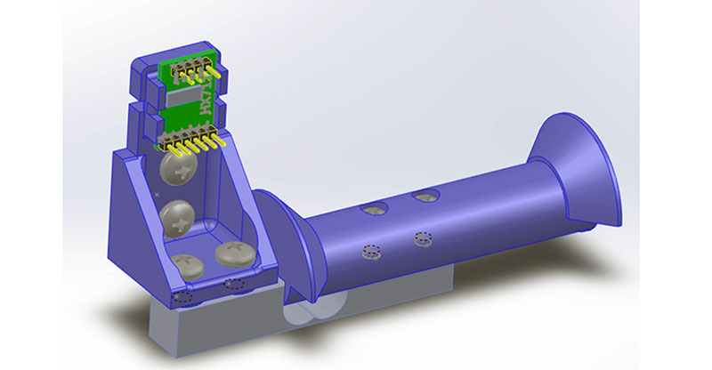
FIGURE 3. A load cell beam is integrated into the spool holder.
To keep things simple and inexpensive, I chose the small Arduino Nano processor (<$10) to take the weight measurements and perform the weight-to-length conversion. An inexpensive (~$8.50) four-line LCD display serves to show both the measured weight as well as the estimated remaining filament length values.
With this information at my fingertips, it became easy to check the length remaining against the slicer Filament needed number before starting every new print. I found this approach minimized unneeded spool changes, prevented filament runouts, and provided peace of mind.
The Spool Scale Display
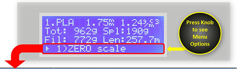
The basic format of the resulting display is depicted in Figure 4.

FIGURE 4. LCD display format.
The filament name, diameter, and density values appear on the top row. Total measured weight (Tot:) and Spool weight (Spl:) values are shown on row 2.
Row 3 shows just the Filament weight (Fil:) as well as the resulting total filament length estimate (Len). Since the Spool Scale takes continuous readings, the weight and length readouts are updated in near real time. A brief press of a push and turn rotary control knob brings up a list of menu options on row 4 of the LCD display.
Project Features Overview
It only takes an Arduino Nano CPU and a few other parts to make this purpose-built 3D printer Spool Scale. This design has the following features and functions:
• Provides direct readout of 3D printer filament weight (kg) and length (m).
• Load cell integrated right into the filament spool holder:
✓ Filament weight measurements are made without moving the spool on and off a scale.
✓ A simple printer-frame mounted spool holder can be readily adapted to bench-top holder style.
• Empty spool weight values are easily entered using a rotary control.
✓ NOTE: An accurate empty spool weight value provides the best results!
• Filament diameter parameter can be easily fine-tuned as needed.
• Filament Type is easily selected.
✓ Onboard database for PLA, ABS, ASA, PETG, NYLN, and many others preloaded.
✓ Filament names and parameters are easily adjusted to match the specs of your specific filaments.
• Simple, easy to build, inexpensive — uses readily available modules and parts.
✓ Arduino Nano (or Uno) CPU.
✓ 2-5 kg load cell with I2C HX711 load cell interface.
✓ Four-line x 20-character LCD display readout.
✓ Single push and turn rotary control provide for an easy-to-use operator interface.
• Readily powered from wall wart supply or a 12 VDC tap right from your printer.
• Easy-to-use ZERO-SCALE and weight CALIBRATION routines are built into the operator interface.
• Easily programmed and customized — Arduino Integrated Development Environment (IDE) to the rescue!
• Database values and other settings are stored in EEPROM memory and automatically updated when changed.
✓ The latest operator updates and calibrations are retained and restored through power on-off cycles.
• Compact — Display fits into a small 3D printed case or can be readily panel-mounted directly to your printer.
The Strain Gauge Load Cell — How It Works
A strain gauge is a sensor that transforms a mechanically applied force into a change of electrical resistance. That is, the nominal resistance of the sensor changes when it is mechanically stretched or compressed. When constructed as a thin film sensor, a strain gauge can be bonded (i.e., glued) to an aluminum support beam (Figure 5). In this way, the strain gauge will react to the deflection of the beam as the beam is subjected to a mechanical load.
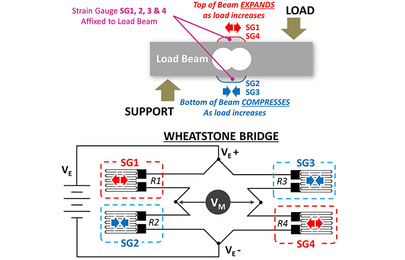
FIGURE 5. A basic load cell.
Figure 5 shows how a set of strain gauge elements (when attached to a load beam) can become part of a Wheatstone bridge electrical circuit. When the load beam is unloaded (gauges are ‘unstressed’), R1=R2 and R3=R4. In the unstressed state, it’s seen that the differential output voltage VM will be zero.
As gauge SG1 and SG4 are stressed into expansion while SG2 and SG3 are stressed into compression, the bridge becomes unbalanced and output voltage VM becomes a non-zero value proportional to the mechanical load placed on the beam. In this way, the deflection of the mechanical beam (as it is loaded by the weight of the printer filament) is translated into a voltage that can be measured.
Electrical Considerations
To be useful, the excitation voltage applied across the Wheatstone bridge (VE in Figure 5) must be well regulated and low noise. Furthermore, since the actual resistance change of the strain gauges is small, the differential output signal must be amplified before it can be readily measured. Lastly, the amplified bridge output voltage must be fed to an analog-to-digital converter (ADC) and sent to a CPU for processing and manipulation.
If this all sounds complex, don’t despair! We’re fortunate that a low cost A/D breakout board specifically designed for weight measuring strain gauge use is available. The interface board uses the HX711 Weight Scale ADC integrated circuit which handles all the tough electrical work.
This IC is able to provide power to excite the Wheatstone bridge, amplify the sensor output signal, and perform a precision A/D conversion. A simple two-wire digital interface from the HX711 delivers a signed 24-bit digital value proportional to the beam deflection to the CPU. A downloadable HX711 Arduino library (see Resources) makes the software tasks a piece of cake.
Load Cell Sourcing
A search for “digital load cell” on Amazon or eBay delivers a raft of options. A kit consisting of a set of strain gauges pre-mounted to an aluminum bar plus the HX711 interface board as shown in Figure 6 is available from multiple vendors.
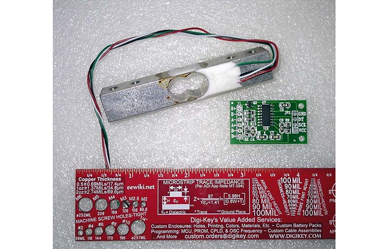
FIGURE 6. Load cell and weight scale interface board combination.
This greatly simplifies the Spool Scale project. The load cell itself is an aluminum beam with strain gauges already pre-mounted beneath a protective coating. As in Figure 7, the aluminum beam has a pair of large holes going through it. The size and location of these holes controls how the beam will flex and deform under load and sets the load capacity of the completed assembly.
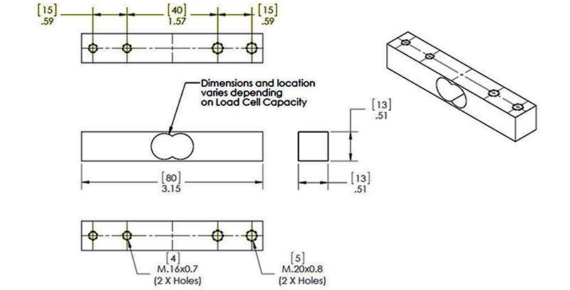
FIGURE 7. Details of a 5 kg load cell beam.
Load cell kits having maximum weight measurement ranges from 100g on up to 50 kg or more are available in the $3 to $15 range. Admittedly, these are not industrial grade, fully calibrated, or “traceable to the National Institute of Standards and Technology.” However, with a little love and care, they can easily serve our needs.
What load cell capacity do we need?
Figure 8 shows my weight range calculations for the Spool Scale load cell.

FIGURE 8. Capacity calculations.
While this shows the 2 kg rating should work fine, I ended up buying a 5 kg unit. Figure 7 shows the physical measurements which I extracted off my 5 kg load beam. CAUTION: Make your own measurements as the dimensions and mounting hole sizes do vary by load cell capacity and may also vary by supplier.
A Basic Spool Holder Design
For this project, it’s necessary to incorporate the aluminum load cell beam inside of a filament spool holder bar. A quick search for “spool holder” on thingiverse.com revealed hundreds of hits, from the simple to the complex.
To get started, I chose to stay simple, and designed the basic spool holder shown back in Figure 3. This design directly mounts to the 20-20 rail frame of my TRONXY 3D printer. In the cross-section view of this design (Figure 9), the load cell beam features a pair of threaded mounting holes on each end of the beam. These are used to mechanically fasten the load cell to the Frame Mount support (left side) and Spool Holder load arm (right side).
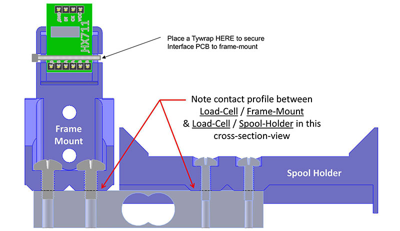
FIGURE 9. Cross-section view of the load cell mounting.
It’s important that just these mounting areas contact the load cell beam. Also, take care to avoid any contact to the protective covering over the strain gauges themselves.
Although this is a very simple spool holder (Figure 10), I found that it worked well and didn’t feel the need to further enhance the holder with ball bearings or any of the other myriad of new and improved variations found on Thingiverse. STL and detailed part drawings for this simple mount are found in the download material; these can be a launching point for you to adapt a load cell beam into your favorite spool holder variant. The wires from the strain gauge elements are directly connected to the HX711 interface board. A multi-conductor cable can be used to connect the interface board to the display/CPU/Operator Interface control panel, as well as bring power and ground into the project.
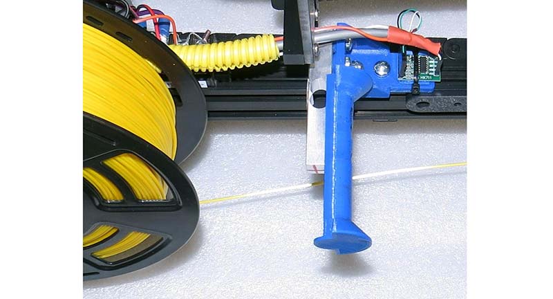
FIGURE 10. A basic frame-mounted spool holder. To expose the spool holder details, the spool of yellow filament has been removed and placed on the table right below the spool holder arm it usually rides on.
Project Details
The complete schematic for the Spool Scale is shown in Figure 11. The Spool Scale can be powered by a simple 9 to 12 VDC wall wart or as I have done, from +12 VDC “stolen” right from my 3D printer. The user interacts with the scale with a single push-and-turn rotary encoder. To keep things organized, I created a simple 3D-printable frame that mounts the Nano CPU immediately behind the 4x24 LCD display. In this way, the LCD/CPU combo can be easily panel-mounted or alternately placed inside of a small enclosure.
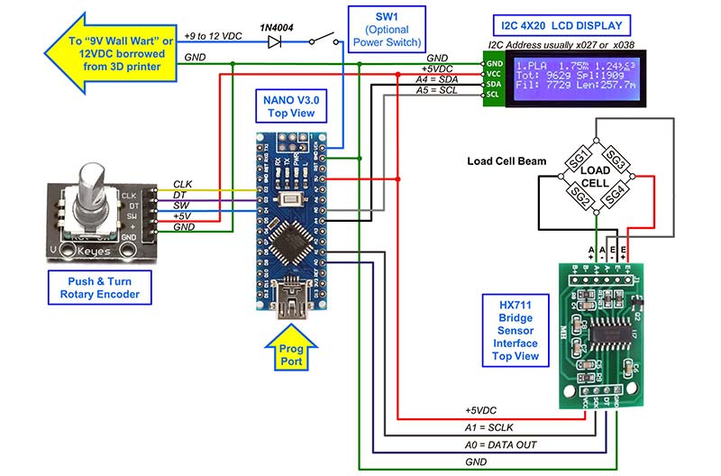
FIGURE 11. Spool Scale schematic.
Building the Spool Scale and Getting the Software Going
Once the 3D parts are printed, the actual hardware build is straightforward and accomplished with simple point-to-point wiring. You’ll need the Arduino IDE (I used version 1.8.9) installed on your PC in order to compile and upload the code into the Nano. The download material contains the Arduino main-line source code for this project which you’ll need to put into a “SpoolScale_VERx.xx” subdirectory you create on your PC. Per the Arduino rules, the subdirectory name must be the same as the mainline source file name. Lastly, you’ll also need to download and install the additional libraries shown in Figure 12.
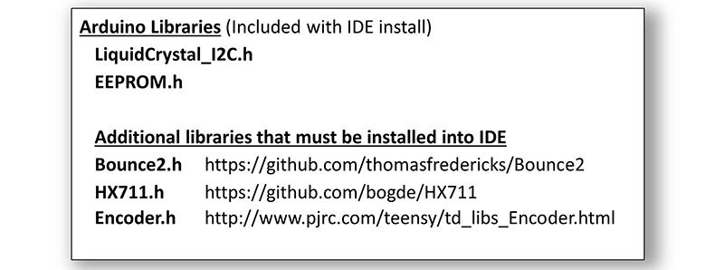
FIGURE 12. Software libraries used in the project.
With all the code and libraries installed, from the IDE “Tools” menu, select board type: Nano; Processor: ATmega328P (old bootloader), then set the correct COM PORT. You’ll know that your libraries are properly installed when you can successfully complete an error-free test compile.
Communications to the Nano board are confirmed by a successful upload.
Software Summary
The main-line code is fairly basic and simply runs a loop that repeatedly measures total weight, filters the reading a bit, calculates the filament length, and updates the display. This loop also checks for operator knob-press actions where it branches to the specific routines coded to perform each menu option. You’ll find lots of comments (too many?) that explain how things work. Feel free to cruise through the code to add your own enhancements (and bug fixes!).
First Time Upload and Initialization
Once you’ve verified that your wiring and IDE setup are good to go, connect the Nano to your PC and upload the code. After the upload, the code will immediately begin running and should briefly display the program version number and the compile date/time on the LCD display. It will then show a message reporting that NO EEPROM database was found and SCALE ZERO and CALIBRATION are required. A few seconds later, the program will launch into the main loop and begin displaying weight and filament length values. Of course, these values will be bogus until the SCALE ZERO and CALIBRATION steps have been completed.
A Few Debugging Notes
- If the LCD back-light doesn’t immediately illuminate on power-up, check to see that the backlight jumper on the I2C daughterboard mounted to the rear of the LCD is in place. Also, be sure that the red LED on the daughterboard and Nano CPU board are on; when both are lit, proper power and ground is confirmed.
- If you still can’t see characters on the LCD or they exhibit poor contrast, the LCD CONTRAST POT should be adjusted. The CONTRAST POT is found on the I2C daughterboard mounted on the rear of the LCD.
- If you still don’t see the expected text on the display at startup, check the LCD datasheet to double-check the LCD module I2C address. Common LCD I2C addresses that I’ve seen are 0x27 and 0x38, but yours could be different. In any event, you may need to change the main-line code to match your specific display. To do this, search the code for #define I2C_ADDR and update the hex address value to match your LCD display.
Using the Spool Scale Interface
After the power-up initialization, the Spool Scale display will automatically measure and display weight and filament length estimates. To select additional functions or change settings, simply press the rotary control knob. This will cause the menu options line to appear on the bottom row of the LCD display. Simply turn the control to step through the selections, pressing the knob when you reach the option you want. A complete listing of menu functions is found in Table 1.
| MENU ITEM |
DESCRIPTION |
| 1) ZERO scale |
Remove all loads from holder and press to perform SCALE-ZERO process. The new SCALE-ZERO point will be auto-saved to EEPROM. |
| 2) Chng SPOOL WT |
Change the empty SPOOL WEIGHT VALUE. Changes will be auto-saved to EEPROM. |
| 3) Select Filament |
Make a new selection from the FILAMENT DATABASE. New selection will become the active filament and auto-saved to EEPROM. |
| 4) Chng FIL DENS |
Change the filament DENSITY value for the currently active filament. Changes will become active and be auto-saved into the DATABASE. |
| 5) Chng FIL DIA |
Change the filament DIAMETER value for the currently active filament. Changes will become active and auto-saved into the DATABASE. |
| 6) Chng FIL NAME |
Change the NAME (four-letter abbreviation) of the currently active filament. Changes will become active and auto-saved into the DATABASE. |
| 7) Save to EEPROM |
Save all active values into the FILAMENT & CAL-CONFIG databases. This function is not usually used as each option auto-saves any changes. |
| 8) Calibrate Scale |
Place a known weight (350-1,500 g) onto the spool holder and then use the rotary control to dial-in that weight value on the display. Upon completion, a new calibration factor is generated and saved to EEPROM. |
| 9) Set Scale Filter |
Increase this setting to slow down and stabilize read-out; decrease the setting to quicken display response. Changes are auto-saved to EEPROM. |
| 10) Serial DB Dump |
This option will transmit the current database values to the serial port. Note: IDE must be connected to the CPU and the serial monitor active to receive this data. Serial monitor baud rate must be set to 115200. |
| 11) Erase EEPROM |
Erase the EEPROM and use first-time defaults. CAUTION: All calibration and filament database changes made by operator will be lost. Scale will reinitialize to hard-coded/first-time start-up values on next power cycle. |
| 12) Exit Menu |
Leave menu mode and blank row 4 of the LCD display. |
TABLE 1.
The Scale Calibration Process
In order to convert A/D counts as received from the HX711 chip into actual weight values in grams, a zero offset data point (a.k.a., scale tare) must be measured and a counts-to-grams scale factor must be determined. An easy-to-use SCALE CALIBRATION function helps accomplish these tasks.
To calibrate the Spool Scale, it’s necessary to have a known weight test load in the 250 to 1,500 gram range that can be hung from the spool holder arm. While you can purchase a precision weight set for calibration, I simply measured a spool of filament with my postal scale and recorded its weight reading (in grams). I then used this spool as my known weight test load. With this weight standard in hand, calibration can begin.
1. Using the push-and-turn control, bring up the menu bar and select item: 8) Scale Calibration.
a) Remove all loads from the Spool Scale arm.
b) When asked “Do you want to ZERO Scale?” select YES and push the knob.
2. When the ZERO process has completed:
a) Place the known weight test load onto the Spool Scale arm.
b) Use the rotary control and dial-in the postal scale weight value (in kg) for your known weight test load.
c) Press the knob of the rotary control when the correct value is set.
3. The scale will now average 10 successive A/D measurements and calculate a calibration factor.
a) When asked “Accept and Proceed?” select YES and push the knob.
4. Calibration is now complete.
a) The ZERO-OFFSET and CALIBRATION-FACTOR values will be saved to EEPROM.
b) The scale exits CALIBRATION MODE and will begin running in its normal main-line ‘measure & display’ loop.
5. To verify calibration:
a) Leave the known weight test load on the Spool Scale arm after calibration and let the Spool Scale measure its TOTAL WEIGHT.
b) The TOTAL WEIGHT reading displayed on the LCD should match your postal scale known weight value.
Note that menu option 1 allows you to zero the scale at any time. Do this periodically for best accuracy.
The Filament Database
The Spool Scale includes an onboard database of key filament parameters. The structure of this database is:
//Define Filament DataBase Structure
struct FILAMENT_DATABASE
{
char Name[5]; // 5 Bytes - Filament Name(4 chars show on LCD)
float Dia; // 4 Bytes - Filament Diameter in mm
float Dens; // 4 Bytes - Filament Density in g/cm^3
// ---------
// 13 Bytes for each filament - type in data base
};
Note that the five bytes defined for each filament name consist of four ASCII characters plus a null terminator. As such, only the first four characters will show up on the LCD screen to identify the filament name. Up to 16 filament types can be held in the onboard EEPROM database. I searched the Internet to find ‘nominal filament density values’ for the usual filament types and these initial values will be loaded into the filament database:
//Uncomment the appropriate line to set default filament diameter
float const Default_Fil_Diam = 1.75; //Value is in mm
//float const Default_Fil_Diam = 3.00; //Value is in mm
// Ram & EEPROM is Tight! With FnumMax = 16, we
// use-up 208 Bytes of RAM & EEPROM (16 x 13 = 208)
// for each FILAMENT_DATABASE structure we define.
struct FILAMENT_DATABASE FilType_DEFAULT[FnumMax] = {
//Name ,Diameter_mm ,Density_g/cm^3
{“PLA “,Default_Fil_Diam,1.24}, //00 (LCD # = 1)
{“ABS “,Default_Fil_Diam,1.04}, //01
{“ASA “,Default_Fil_Diam,1.07}, //02
{“PETG”,Default_Fil_Diam,1.27}, //03
{“NYLN”,Default_Fil_Diam,1.08}, //04
{“PlyC”,Default_Fil_Diam,1.20}, //05
{“HIPS”,Default_Fil_Diam,1.07}, //06
{“PVA “,Default_Fil_Diam,1.19}, //07
{“TPU “,Default_Fil_Diam,1.20}, //08
{“TPE “,Default_Fil_Diam,1.20}, //09
{“PMMA”,Default_Fil_Diam,1.18}, //10
{“Copr”,Default_Fil_Diam,3.90}, //11
{“????”,Default_Fil_Diam,0.0}, //12
{“????”,Default_Fil_Diam,0.0}, //13
{“????”,Default_Fil_Diam,0.0}, //14
{“????”,Default_Fil_Diam,0.0} //15 (LCD # = 16)
};
Once you’re up and running, you can update the database using the rotary control and menu options 4, 5, and 6. You should find it easy to fine-tune the entries to match your favorite filaments types and manufacturer density constants. Any updates you make will be automatically saved to the EEPROM database.
Setting the Empty Spool Weight
The Spool Scale must subtract the empty spool weight value from the total weight measurement it’s taking in order to determine the filament weight by itself. I’ve found that empty spool weights vary greatly from supplier to supplier and can range from 80g to more than 200g. To accommodate this variability, menu option 2 allows the operator to enter the empty spool weight value for the current filament in-use. While some filament suppliers specify their empty spool weight on their websites, most do not. So, the best way to set this value is to measure an empty spool of the same brand (left over from a prior runout) using the Spool Scale and enter that value using menu option 2. Alternately, you can load and measure a fresh spool, subtract 1 kg from that reading, and use this as a “best guess” empty spool weight value. While imperfect, this will get you started until you can determine a more accurate value.
How well does it work?
As a linearity test, I zeroed the scale, set the spool weight to 0, and placed a three meter length of 1.75 mm diameter filament onto the scale. The scale did indeed display an estimated length of 3.0 meters! I then reset the spool weight back to a more nominal value of 125 grams and put a near full spool of filament onto the scale. It reported the estimated length at 286.2 meters. I then added the three meter length of filament by hanging it on the holder along with the near-full spool. It now reported 289.3 meters of total length: a difference of 3.1 meters! Not bad!
Some Operating Guidelines
In practice, I think the biggest issue affecting the accuracy of the filament length estimate will be getting and setting an accurate empty spool weight value. The rigidity, style, and shape of the spool side-wall cutouts vary greatly from supplier to supplier which causes the empty spool weight values to vary greatly. This is problematic for our length estimates.
A simple analysis shows that an empty spool weight error of 50 grams, for example, will change the estimated length readout of 1.75 mm diameter PLA by about 20 meters. This means that if your empty spool weight guess is low by 50 grams, the scale will exaggerate the length estimate by 20 meters! This could lead to a filament runout if you’re expecting to consume the filament down to the last few meters.
Conversely, if your empty spool weight guess is high by 50 grams, the scale will under-report the length by 20 meters, giving you some margin when working down to the end of a spool.
I’ve found the Spool Scale to be a very handy tool to help manage filament use. However, one should follow a few operational guidelines to avoid surprises:
• The absolute best way to set the empty spool weight value is by direct measurement of an empty spool.
✓ This should work well if you stick with one filament vendor and that vendor has a stable, repeatable spool style.
• If you must estimate the spool weight with a guess, use a guess on the high side!
✓ This will give you an additional reserve length margin.
✓ Padding the empty spool weight by 50 grams or so should keep you out of trouble while giving you reasonable assurance that you won’t run out on those long prints.
• I’ve gotten into the habit of putting a sticker on each spool with its “fresh spool total weight” and the “best-guess empty spool weight” value to use. That way, every time I load that spool, I can dial in the correct empty spool weight value into the scale.
Other Applications and Enhancements
The basics of weight-to-length conversions presented here allow anyone with a postal scale to make a periodic quantitative assessment of 3D filament status. By adding this purpose-built scale to your 3D setup, it becomes easy to continuously monitor filament status and prevent filament runouts.
Even if you don’t have a 3D printer application, the core design concepts presented can be the basis for your own digital scale project. For example, it’s easy to see how a traditional scale platform could be mounted to a load beam to create a general-purpose scale. With a few code changes, the display could easily show the measurements in multiple units (i.e., grams, kilograms, pounds, ounces).
It might also be useful to add a counting function so you could put a quantity of screws or other loose parts onto the platform and have the scale not only report the total weight, but also the quantity of the items present.
Don’t hesitate to play with the design and code set to fine-tune it to meet your application-specific needs!
Happy weighing! NV
Parts List
| ITEM |
QTY |
DESCRIPTION |
SOURCE |
NOTES |
| Electronics |
| 1 |
1 |
ARDUINO NANO CPU |
arduino.cc, eBay, Amazon |
Suggest Nano Version 3. |
| 2 |
1 |
POWER SUPPLY |
Sparkfun, eBay, Amazon |
Power for CPU. Consider using +12 VDC from 3D printer. |
| 3 |
1 |
ROTARY ENCODER |
Sparkfun, eBay, Amazon |
Be sure unit has clock, data, and PB switch outputs. |
| 4 |
1 |
20x4 A/N LCD DISPLAY W/ I2C INTERFACE |
Sparkfun, eBay, Amazon |
Order unit with I2C interface; model w/backlight suggested. |
| 5 |
1 |
LOAD CELL W/ INTERFACE CIRCUIT |
Sparkfun, eBay, Amazon |
Be sure interface is 5V and uses HX711 with two-wire interface. |
| |
1 |
DIODE |
Various |
Power protection diode, 1N4004, or similar 50V, 1A. |
| 6 |
1 |
POWER SWITCH |
Various |
Optional, builder’s choice. |
| 7 |
1 |
MISC WIRING, CONNECTORS & ASSEMBY HARDWARE |
Various |
Builder’s choice, as-needed items. |
| Mechanics |
| 8 |
1 |
FRAME MOUNT |
3D print |
See downloads for details and options. |
| 9 |
1 |
SPOOL HOLDER |
3D print |
See downloads for details and options. |
| 10 |
2 |
M5 x 12 mm PhilHd |
Various |
Frame mount attachment to load cell beam. |
| 11 |
2 |
M4 x 12 mm PhilHd |
Various |
Spool holder attachment to load cell beam. |
| 12 |
As Rqd |
MISC SCREWS/T-NUTS |
Various |
Misc fasteners and cable ties (Ty-Rap) as needed to complete holder assembly. |
| Control Panel/Enclosure Options — A custom case for this project is available in the Nuts & Volts webstore. |
| 13 |
1 |
FRONT PANEL (Frame Mount) |
3D print |
See downloads for details and options. |
| 14 |
1 |
CASE FRONT/REAR SET (Stand-alone Case) |
3D print |
See downloads for details and options. |
| 15 |
1 |
CPU/LCD MOUNTING FRAME |
3D print |
Holds CPU to rear of LCD display. See downloads for details and options. |
| 16 |
2 |
TILT MOUNT (Stand-alone Case) |
3D print |
See downloads for details and options. |
| 17 |
2 |
TILT BASE (Stand-alone Case) |
3D print |
See downloads for details and options. |
| 18 |
As Rqd |
MISC SCREWS/T-NUTS |
3D print |
4-40 x .5 in screws and other fasteners needed to assemble LCD/CPU to front panel and attach rear enclosure panel. |
Filament Scale Printed Components are available here.
RESOURCES
Strain gauge operation and their use in digital scale applications
https://en.wikipedia.org/wiki/Strain_gauge
https://wiki.restarters.net/Digital_weighing_scales
Detailed explanation of Wheatstone bridge circuit
https://en.wikipedia.org/wiki/Wheatstone_bridge
Arduino IDE, Arduino libraries, and useful guides & references
https://www.arduino.cc
Spool Scale source code, 3D print files, and more hardware details
https://github.com/Ed-EE-Eng/Spool_Scale_Project
Bounce2 pushbutton debouncing library
https://github.com/thomasfredericks/Bounce2
Strain gauge scale interface library
https://github.com/bogde/HX711
Push-and-turn encoder library
www.pjrc.com/teensy/td_libs_Encoder.html
Downloads
Source code
STL files
Design Notes