Magnets are magic! Yes, I know they are science, with moving electric charges and magnetic moments of elementary particles within the metal structure, but they still seem like magic.
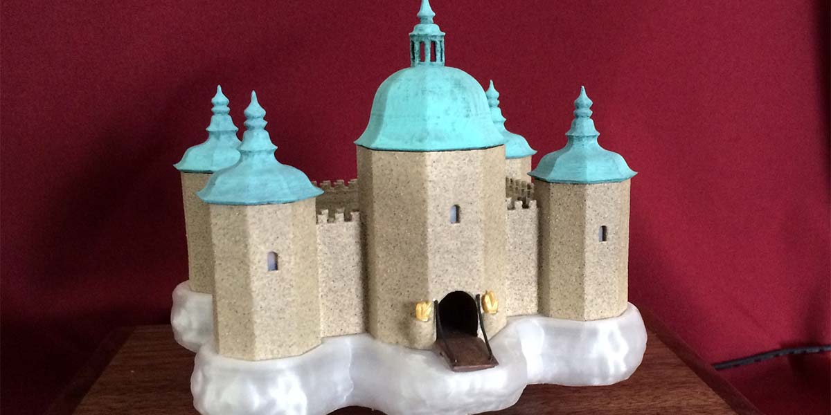
We can get them to stick to things and repel each other, but to suspend something in air repelled by a magnetic field is a bit of a trick. I wanted to make a castle floating in the clouds, and also wanted electricity to wirelessly cross the space of flotation to power 24 lights in the castle and in the clouds. A video can be seen at https://youtu.be/D4HrKYEHSoY.
The magnetic field of a simple magnet will not allow a stable suspension of a magnet in space repelled from below. This is explained by Earnshaw’s theorem, which says that stable stationary equilibrium cannot be obtained with just the magnets. We need some electronic control of the situation to stabilize magnetic levitation. This is accomplished by using electromagnet coils, and Hall-effect magnetic sensors to sense the field and trigger minute corrections to the field to maintain balance.
I really wanted to make my own circuit and use a microcontroller to adjust the field. I used a circle of stacks of Neodymium (Nd) magnets. I was not successful in doing this. The microcontroller (a PIC at 50 MHz) was not fast enough to achieve the balance. I believed an analog circuit is what would be required; this is not within my abilities. So, I gave up on this part and bought a magnetic levitation unit (Figure 1).
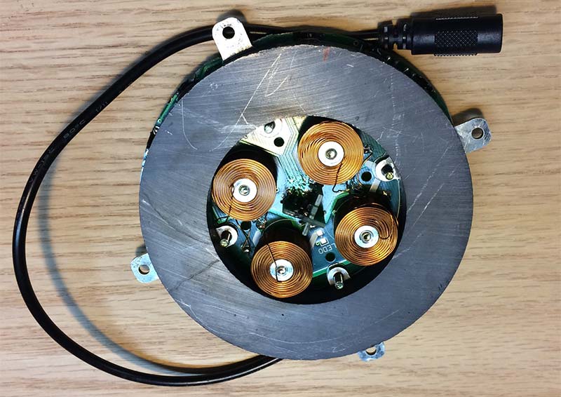
FIGURE 1. The ring magnet flotation device.
The wireless transfer of power was something I could do, but it took quite a bit of experimentation to achieve this. Charging coils and circuits are available to charge phones and other things wirelessly, but they rely on very close contact between the transmitting and receiving coils.
I tried one of these, and as soon as the coils are separated by even a small amount, the current drops to almost nothing. I wanted the current to travel an inch, and found out this was not as easy to accomplish.
Magnetic Levitation
To help me see what I might be missing when attempting my own levitation circuit, I got a cheap small device that ran on five volts and used a ring of stacked Nd magnets. It didn’t support very much weight and was rather difficult to achieve flotation. It didn’t always like to stay floating if there were bumps to the table or other disturbances.
Then, I got one with a big ring magnet that supports 500 grams and I was in business! It floats my castle nicely with a good degree of stability, and it’s not hard to get the castle into a floating position.
With this big ring magnet and a small compass needle, I mapped out the magnetic field above the ring magnet, with the red points of the arrows representing north (see Figure 2).
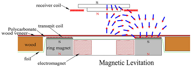
FIGURE 2. The mounting of the magnet. Tiny compass pointers show the direction of the magnetic field without the upper magnets in place.
The field was detected with the power off and without the upper magnets in place. I first thought that the south of the ring magnet should face the south of the opposing floating magnet. Nope!
The top of the ring magnet is south, but there is a zone of north above the center of the hole in the ring magnet. The top of this zone is the sweet spot for levitation to repel the north pole of the magnet above.
The levitation system causes the castle to rotate after a minute or so. I can’t decide whether I like that or not. I think it may be related to the mounting of the Hall sensors being slightly off of 90° from each other, and intended by the manufacturer to make it rotate.
Wireless Energy Transfer
The next step was to send electricity across the one inch gap between the bottom and top magnets. The transmitting current is a 1 MHz alternating current. An oscillator creates a 1 MHz signal, and is amplified by a MOSFET.
I wound 10 different coils to see what would transfer the current the best (Figure 3). I found that loosely spaced #14 bare copper wire in the flat lower coil tuned with capacitors worked for the transmission.
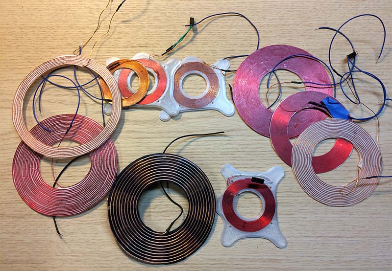
FIGURE 3. Ten attempts to get a good working set of coils. Front and center are the final lower transmission and upper receiving coils.
To receive the energy above is a three-layer closely wound flat coil with #22 magnet wire. Putting any capacitance in the receive circuit only made it worse. My final coils are the two at the bottom center of Figure 3. The bottom coil is on the left and the upper coil is on the right.
The lower coil is made by straightening the wire and then forming it roughly into a flat coil. Placing the wire on a hard flat surface and pounding it gently with a plastic mallet while rotating the wire straightened it well for me. Some people have gotten good results in straightening by stretching the wire with a strong force.
I made a 3D printed matrix to hold onto the wire and guided the wire into the plastic matrix. If there were any bends to make the wire curve out of the flat plane of the coil, it wouldn’t be flat enough. The idea is to get the wire as close as possible to where it needs to be, and the matrix just guides it into position. The matrix is not strong enough to hold the wire flat all by itself.
I then put eight one-inch wide spokes of epoxy on the coil and matrix, sandwiched it all between layers of waxed paper, and clamped it between wood boards in that position for 24 hours. This coil gets warm during operation, so covering it all with epoxy may inhibit dissipation of the heat. I attached a lead of #26 stranded wire to the center of the coil, so that its thinness would allow the ring magnet to be as close as possible to the upper surface of the box. At the edge of the coil, it’s attached to a lead of shielded coaxial cable.
For the upper receiving coil, first I cut out a layer of Grafix double-tack archive film and then wound the flat coil layer by hand onto it, pressing it into position with a plastic instrument as shown in Figure 4.
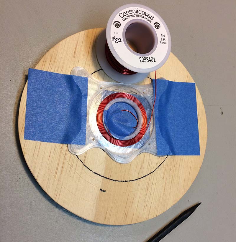
FIGURE 4. Winding the upper coil inside the bottom of the clouds.
After the first layer was wound inside to outside, I placed another layer of double-stick film and layer 2 was wound outside to inside, then layer 3 similarly from inside to outside. Next, I coated it with epoxy and sandwiched it with wax paper and wood boards until set.
At first, I supplied 12 volts to the levitation device and used this also to run the transmit coil. I used a DC-DC converter to get five volts to run the oscillator. The circuit and magnet mounted in the box is seen in Figure 5.
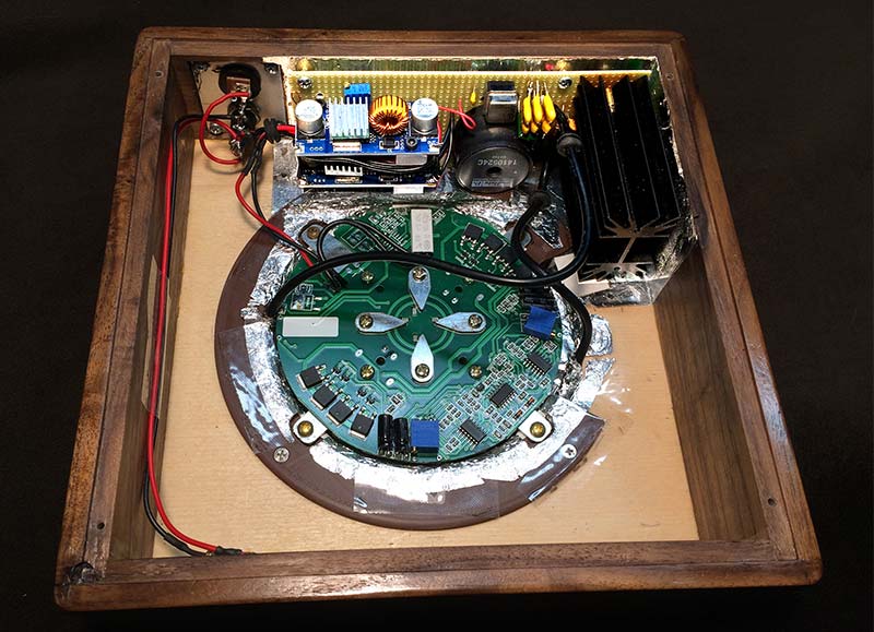
FIGURE 5. Mounting of the ring magnet device and the circuit board.
I found that despite using a large heatsink, after about an hour, the MOSFET and its heatsink got so hot that the lights quit working. The magnetic levitation could keep going all day, but I had working lights only for an hour.
I brought it to display at a Maker Faire and was disappointed to have my creation not performing at full function. Many people there were so fascinated by the levitation, they didn’t seem to miss the lights, but I knew it could do more.
I also felt that the LEDs could be a little brighter, which entailed more current and more heat. I changed to a 15 volt power supply for the MOSFET amplifier to drive the energy transfer coil. I then used two DC-DC converters to get 12 volts for the levitation device and five volts for the oscillator. I attached each one to a 120Ω two-watt resistor for a dummy load to set the voltage with the trim pot.
After the voltage was set, I wired them into the rest of the circuit. I mounted a small fan in the base to draw air past the circuitry, and now it can run all day with working lights.
I used a four amp power supply. Once the castle gets floating, it only uses about one amp of current. While trying to achieve flotation, however, more current is needed and using too small of a power supply makes it rather difficult to get the castle to float. Plus, it’s not as stable when it’s floating.
I was a little ambitious using 24 LEDs in the castle, but I am happy with how it came out. In person, it looks great, but in photographs using enough light on the whole thing makes the lighting of the clouds not as visible.
If one were to use fewer LEDs, the current requirements would not be as high. It might then be possible to run it all with a 12 volt supply and not use the cooling fan. But then again, the more LEDs, the better!
Problems in Cloud Paradise
I wired everything up on my workbench, with wires all over the place connecting it all. I started the magnet supporting the castle, set the transmitting coil loosely on top of it, and got the energy to wirelessly transfer. I made a nice wood box to hold it, put it all inside, and the magnet wouldn’t levitate anymore!
The energy transmission was electrically interfering with the circuitry of the flotation control magnets. I used aluminum foil to line the box where the transmission circuitry is located, and also to go between the magnetic levitation unit and the transmission coil. It’s important that the foil does not touch any of the four mounting tabs for the ring magnet unit because shorting these tabs to ground will cause it all not to function. The foil should also not touch any of the circuitry of the ring magnet unit.
Grafix double-tack film allowed me to stick the aluminum foil to the inside of the box (double-stick Scotch™ tape could be used for this as well). I made an aluminum shield to go around the transmission circuits that connected electrically to the foil, and it all is connected to ground. The inside of the bottom cover — made of thin polycarbonate plastic — is lined with aluminum foil to cover the transmission circuit and power supplies.
I used shielded coaxial wire to go from the transmission circuit to the transmitting coil. It worked well, and then later it didn’t work so well. I think that possibly the connection of the shielding walls to the foil lining the box was not as good as it should have been.
I made another shield to cover the levitation magnet assembly, and improved all my connections between the shields and the foil. Now it works!
The shielding was necessary to isolate the powerful 1 MHz transmission current from the delicate balancing currents used to maintain a stable levitation. The box interior with the shielding in place can be seen in Figure 6.
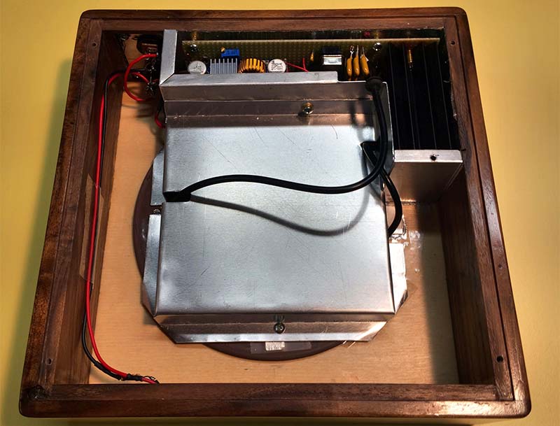
FIGURE 6. Inside the box, with shields in place.
Enclosure
I wanted a nice walnut wood box to enclose it all. For the top, I wanted it to be as thin as possible to make the flotation distance above the wood to appear as large as possible. A thin (1/28”) piece of walnut veneer was epoxy glued to a 1/32” thick piece of polycarbonate plastic to make a very thin top. The plastic was sanded to achieve some roughness for adhesion to the epoxy.
Polycarbonate is “unbreakable,” which was needed to withstand the castle crashing down to the box if someone should give the table a big bump. If it were to break, it would mean remaking the whole box.
Outside the big magnet and coil is a piece of 1/2” plywood with a circular hole to support the entire top except directly over the magnet and coil. (This can be seen back in Figure 2.)
Ventilation is critical for the operation of the MOSFET amplifier. A small fan at the back pulls air through the box and past the heatsink. The ventilation holes can be seen in Figure 7.
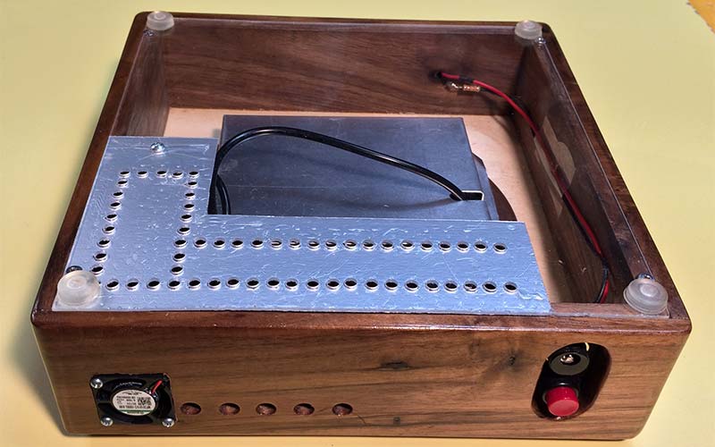
FIGURE 7. The bottom and back of the box, showing the fan and ventilation holes.
If I were to make another one, I would make the box 1/2” longer and wider. The circuitry all fit but was a little tight, and a little more room would have made it easier. A larger box might also simplify the ventilation requirements. Too big of a box, however, would dwarf the castle in size.
The Castle
The castle is printed on a 3D printer. The clouds are printed in clear CPE plastic. The castle body is printed in brown ABS plastic, spray painted with beige paint, and then sprayed with a textured multicolored paint that makes it look a lot like stone.
The tops of the turrets are printed in ABS plastic, and then painted green and textured with a somewhat dry brush with a mixture of green and black acrylic paints to give it a streaked weathered appearance of a copper castle roof. Number 2-56 stainless steel flat head screws fasten the bottom to the clouds, and 4-40 brass screws for the castle to the clouds. They need to be non-magnetic. The roofs of the turrets snap into place. The spire on the very top of the main entrance turret is aluminum, stainless steel wire, and a blob of epoxy at the top.
I didn’t try to make it look like a particular castle, but the Kalmar Castle in Sweden gave me inspiration and so did other European castles. If I were to try another castle, I might look to the Neuschwanstein Castle in Germany for more inspiration.
There are LEDs lighting the inside of the entrance tunnel to the castle, and also lighting the inside hallway to the back door. I originally wanted to have flickering yellow LEDs underneath clear acrylic flames on the torches next to the front entrance, but found that there was not enough current to make them flicker or to get enough light into the flames. Painting the hand sculpted flames with gold paint would have to suffice.
Just outside the back door of the castle there are a man and woman kissing. They’re very tiny, but add a little interest to the situation. I carved the couple out of wax and cast it in silver, then painted it. Figure 8 shows the back of the castle with this amorous couple.
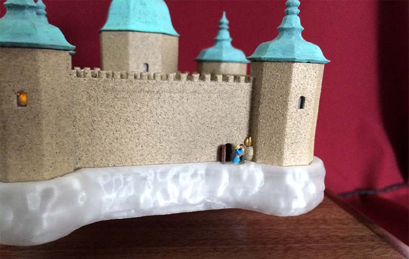
FIGURE 8. Outside the back door, a couple steals a kiss.
Electronics
The circuit diagram is shown in Figure 9. Be sure to use electrostatic precautions for wiring the circuit as the MOSFET is very sensitive to static. I used an anti-static mat and a grounding wrist strap connected to ground for wiring this.
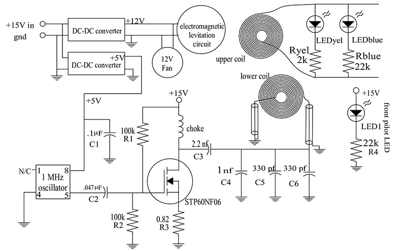
FIGURE 9. The circuit diagram.
Blue LEDs and their resistors are wired and glued into the clouds from the top. The bottom of the clouds is a removable piece that holds the floating magnets and the receiving coil. The receiving coil connects to the cloud LEDs with a header pin connector. The cloud LEDs also have a header pin connector that plugs into the LED circuitry inside the entrance building to the castle. Figure 10 shows the top of the clouds with the castle removed.
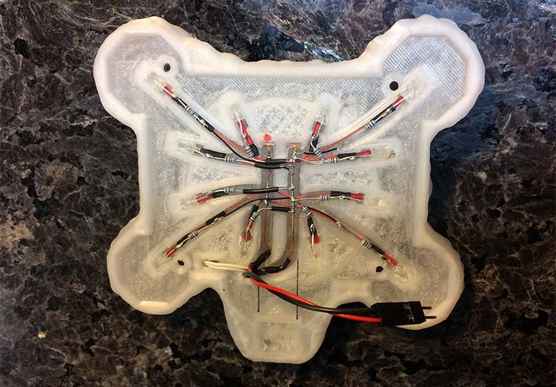
FIGURE 10. Inside the clouds from the top, with the castle removed.
It was a challenge to wire the LEDs in the castle. The LEDs are glued into their mountings that are inside of the windows with a thin piece of translucent plastic over the windows to diffuse the light. Where some wires came close to each other with a possibility of shorting, silicone sealant held them in place.
The circuit for the wireless power transmission and the DC-DC power supplies were all wired up on a piece of 1.7 x 5.25 inch perfboard with solder pads, using point-to-point wiring. Figure 5 shows the circuit board in place, without the shielding.
A printed circuit might take more time to design and solder than just wiring it all by hand since there aren’t too many components. Since this whole thing was an experiment, the perfboard method allowed many additions and changes to the circuit.
An improvement would be to make both leads to the transmission coil from the perfboard come out at the bottom right as shown back in Figure 5. Make those leads connect to the transmission coil at the 2 o’clock position. This will make placing the shielding much easier by not having to make extra holes in the shields, keeping the wires short but allowing enough length to make attaching the circuit board easier.
The wires connecting the power input jack to the circuit board should run close to the back wall for the same reason. When this was in its earlier stages, I didn’t anticipate needing all of the shielding.
The capacitors with the main transmit coil are in parallel to get the right capacitance, since the value of capacitance needed is not available in one capacitor. I tried trimming capacitors to dial it in more accurately; this didn’t work as well as swapping capacitors. While swapping caps, I had an oscilloscope connected across the receiving coil to try for the most voltage that I could get.
The LEDs in the castle are the rectifiers that convert the 1 MHz alternating current to DC. They are diodes, after all. A bridge rectifier or a single diode to rectify the DC sucked up too much voltage and the lights were noticeably dimmer.
The Future
This was very fun to make. It was delightful to see people do a double take when they saw it while walking by at the Maker Faire, and then it drew them in to see it more closely.
Lots of other things could be made to float and have lights. A smaller or simpler castle could use fewer LEDs and then they could be even brighter. I like this one, and the human eye can see the subtleties of light that my camera cannot. NV
The .stl files to load into Cura or other slicing program are located in the downloads. They are ready to print.
If you wish to make modifications to any of the 3D printed parts, then you may wish to modify the parts from my CAD design file. The link to the Fusion 360 CAD file is https://a360.co/2wg3usz.
I used Autodesk Fusion 360. If you’re a hobbyist, you can use the program for free. Go to https://www.autodesk.com/products/fusion-360/free-trial.
The downloads for this article contain other files useful for this project.
Parts List
Downloads
What’s in the zip?
STL Files
Misc Helpful Diagrams and Files