What is a continuity test? I say it depends on your particular use. In my case, it’s usually either for beeping out cables or for beeping out printed circuit board (PCB) assemblies.
I design and build functional equipment to test PCB assemblies. This involves making all sorts of custom cables and the custom board assemblies. The latter often involve hand-soldering SMT components, such as my favorite 80-pin fine-pitched microcontroller. There is plenty of opportunity for error, and a continuity tester is very handy for detecting both shorts and opens.
Somewhere in the 25 ohm area has proven to be a convenient trip point for my use. In other words, if the resistance between my continuity tester probes is less, I get a beep; if the resistance is more, there’s no beep.
For years, I used a simple op-amp based circuit with two AAA batteries, some resistors, and a piezo electric beeper. It served me well, but had two drawbacks:
- I’m getting old, and I work in a noisy environment. Half the time, I can’t hear the beeper, or worse, I imagine that I do hear it.
- I forget to turn it off, so the batteries die.
Most multimeters have a built-in continuity tester, but these also have problems:
- Again, I can’t hear the beeper.
- There is a significant voltage between the probes (7V on my Fluke meter). That voltage can damage some devices (not to mention polarity issues).
- There is a slight but unacceptable delay each time it detects continuity. Frequently, I plant a probe on one pin and ‘rake’ the other pin across IC pins, looking for shorts and opens. That only works when the feedback is ‘instant.’
During a recent vacation, I challenged myself to come up with a design that suits my needs. Most of the time, I go straight for a microcontroller, but this time I decided to use only non-programmable components. I also decided to use only through hole components, to make soldering easier. (I did cheat on this with two SMT transistors, but they are quite large, SMT-wise, and easy to work with.)
Here is my list of requirements:
- Must be loud enough for me to hear it.
- Must turn itself off after a reasonable time (approximately two minutes), but extend the time each time it beeps.
- Must have ‘instant’ response.
- Must have very low probe voltage (~200 mV).
- Must define continuity somewhere in the 25 ohm range.
- No programmable parts.
- All through hole parts (well, almost all).
The schematic is shown in Figure 1. The only IC is the LM339 comparator. The two N-channel MOSFETs may be a bit overkill, but they are fairly inexpensive, and I had several on hand. The resistors are all 1% 1/4 watt, and the 100 µF capacitor is a simple aluminum electrolytic.
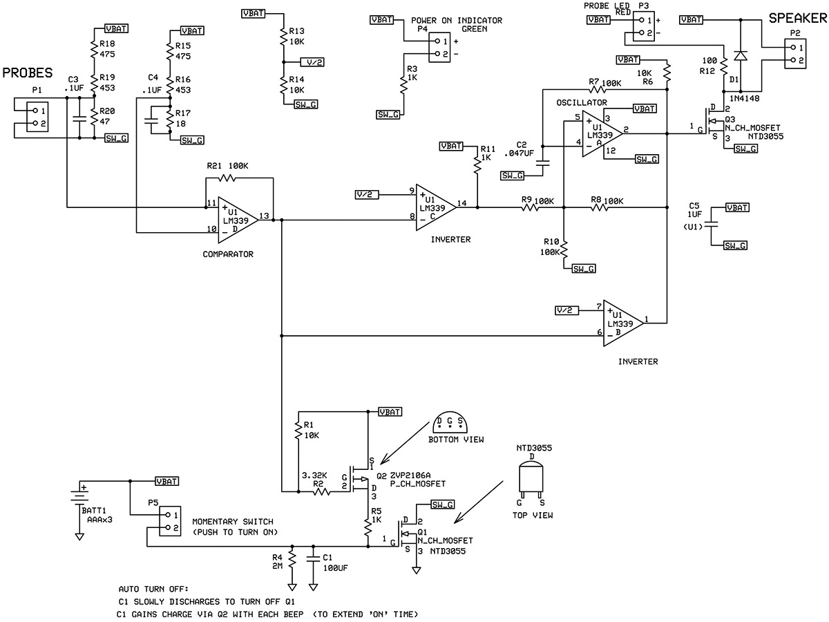
FIGURE 1. Schematic of the continuity tester.
Understanding the Circuit
The power control section is centered around Q1, which is the N-channel MOSFET. It’s being used here as a very low resistance switch to DC ground. Until you press the on button, this circuit draws almost zero current from the batteries. When you do press the on button, capacitor C1 charges up very quickly and Q1 turns on, which provides a ground (which is labeled SW_G) for the circuitry above. The tester is now up and running, and draws about 16 mA while idle (considerably more when beeping). You need to press the on button only briefly to charge C1, then C1 begins discharging slowly through the two megohm resistor.
When the voltage on C1 drops below about 2V, Q1 turns off. The tester is now powered down. However, each time you beep, the output of U1D goes low, and Q2 turns on briefly to pump fresh charge into C1, which extends the on time. I find that the time out (with no refresh beeping) is about 2-1/2 minutes, but that will vary depending mainly on the capacitor tolerance.
The CONTINUITY DETECT section is centered around U1D: the LM339 comparator. The associated resistors, R15-R20, should be no worse than 1%. My tester trips at about 29 ohms. The output (pin 13) of U1D goes low when the probes see continuity (29 ohms or less in my example).
The AUDIO section is an oscillator centered around U1A, followed by an ‘amplifier’ Q3, which is really just an on/off switch pulling current through the speaker. The oscillator consists of U1A, C2, and R7-11. When the probes see no continuity, the output of U1D is high (thanks to pullup resistor R1), and inverter U1C output at pin 14 goes low, which disables the oscillator. When the probes see continuity, the output of U1D pulls low, and inverter U1C output goes high (thanks to pullup R11), which enables the oscillator.
The enabled oscillator outputs a frequency of about 500 Hz (to which my hearing responds better than the ~2 kHz of the typical piezo electric beeper). That output is a square wave that switches Q3 on and off, pulling current through the speaker. Note that while the oscillator is disabled, the output of inverter U1B (pin 1) pulls low, which guarantees that Q3 will draw no current through the speaker. This is where the OPEN DRAIN feature of the LM339 is convenient, allowing the wire OR-ing of the outputs of U1A and U1B.
Construction
This circuit would be fairly easy to construct on a breadboard. I was building more than one, so it made sense for me to have PCBs made. I used ExpressPCB for both the schematic and PCB layouts. Figure 2 shows the assembled component side of the PCB, and Figure 3 shows the solder side.
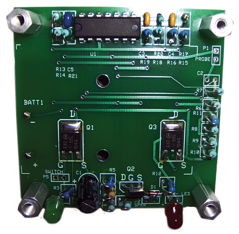
FIGURE 2. My PCB, component side.
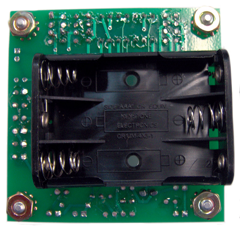
FIGURE 3. My PCB, solder side.
The resistors on my board are installed vertically, with one lead bent over running parallel to the body of the resistor. Anyone who has seen the inside of an early transistor radio will recognize the geometry. It conserves board space without the need for surface-mount components.
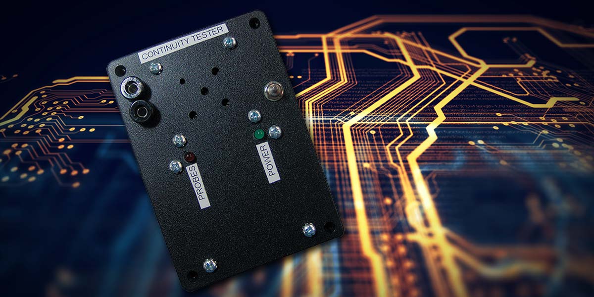
Figure 4 shows the inside of the face of the enclosure. Having all the parts mounted on the face makes it easy to get to the batteries without stressing any wires.
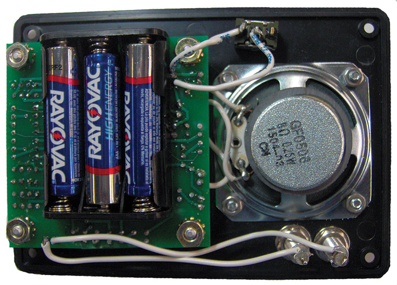
FIGURE 4. Inside cover of enclosure.
There are opportunities to reduce the board size and component count. Surface-mount components could be used, for example. LED1 and LED2 are conveniences and can be eliminated if desired. LED2 is a green LED to indicate when power is on, and LED1 is red and turns on with the beep. Eliminating the LEDs and their associated resistors would extend battery life in addition to reducing component count. However, I find their presence reassuring.
I installed banana plug jacks for the probes, which makes it easy to swap out different types. Sometimes I want a sharp point probe. Sometimes I want a J-Clip or an alligator clip. For beeping out cables, I use a probe with a header pin soldered to the end of the wire. This allows me to insert the pin into a connector socket and poke around with the other probe, eliminating the need for a third hand.
Whatever your particular use, I hope you find this continuity tester helpful. NV
Parts List
| QTY |
REFERENCE |
DESCRIPTION |
MANUFACTURER |
DIGI-KEY |
| 1 |
U1 |
LM339 COMPARATOR |
TEXAS INSTRUMENTS LM339AN |
296-6605-5-ND |
| 2 |
Q1, Q3 |
N-CHANNEL MOSFET |
ON SEMICONDUCTOR NTD3055L104T4G |
NTD3055L104T4GOSCT-ND |
| 1 |
Q2 |
P-CHANNEL MOSFET |
DIODES INC. ZVP2106A |
ZVP2106A-ND |
| 1 |
C1 |
100 µF 6.3V CAPACITOR 20% |
NICHICON UPW0J101MDD1TD |
493-11333-1-ND |
| 1 |
C2 |
.047 µF CERAMIC CAP |
VISHAY B.C. K473K10X7RF5UH5 |
BC2686CT-ND |
| 2 |
C3, C4 |
.1 µF CERAMIC CAP |
VISHAY B.C. K104Z15Y5VF5TL2 |
BC1160CT-ND |
| 1 |
C5 |
1 µF CERAMIC CAP |
AVX 478-3195-ND |
478-3195-ND |
| 1 |
LED1 |
LED RED |
LUMEX SSL-LX5093ID |
67-1105-ND |
| 1 |
LED2 |
LED GREEN |
LUMEX SSL-LX5093GD |
67-1098-ND |
| 3 |
R3, R5, R11 |
1K 1% 1/4W RESISTOR |
YAGEO MFR-25FBF52-1K |
1.00KXBK-ND |
| 1 |
R2 |
3.32K 1% 1/4W RESISTOR |
YAGEO MFR-25FBF52-3K32 |
3.32KXBK |
| 4 |
R1, R6, R13, R14 |
10K 1% 1/4W RESISTOR |
YAGEO MFR-25FBF52-10K |
10.0KXBK-ND |
| 5 |
R7-R10, R21 |
100K 1% 1/4W RESISTOR |
YAGEO MFR-25FBF52-100K |
100KXBK-ND |
| 1 |
R12 |
100 1% 1/4W RESISTOR |
YAGEO MFR-25FBF52-100R |
100XBK-ND |
| 2 |
R15, R18 |
475 1% 1/4W RESISTOR |
YAGEO MFR-25FBF52-475R |
475XBK-ND |
| 2 |
R16, R19 |
453 1% 1/4W RESISTOR |
YAGEO MFR-25FBF52-453R |
453XBK-ND |
| 1 |
R20 |
47 1% 1/4W RESISTOR |
STACKPOLE RNMF14FTC47R0 |
S47CACT-ND |
| 1 |
R17 |
18 1% 1/4W RESISTOR |
PANASONIC ERO-S2PHF18R0 |
P18.0CACT-ND |
| 1 |
R4 |
2M 1% 1/4W RESISTOR |
STACKPOLE RNF14FTD2M00 |
RNF14FTD2M00CT-ND |
| 1 |
D1 |
1N4148 DIODE |
1N4148 |
1N4148FS-ND |
| 1 |
SP1 |
SPEAKER, 8 OHM, .25W |
CUI INC. GP0506 |
G |
| 1 |
PB1 |
PUSHBUTTON SWITCH |
NKK MB2411E1W03 |
360-2143-ND |
| 1 |
BH1 |
BATTERY HOLDER 3xAAA PCB MOUNT |
KEYSTONE 2479 |
36-2479-ND |
| 3 |
|
BATTERY, AAA |
|
|
| 1 |
|
ENCLOSURE |
BUD CU-389 |
377-1220-ND |
| 4 |
|
STANDOFFS, 1/2" 6-32 MALE/FEM |
KEYSTONE 8414 |
36-8414-ND |
| |
|
MISC HARDWARE/WIRE |
|
|
A complete kit is available in the Nuts & Volts webstore.
Downloads
What’s in the zip?
Express PCB File
Bill of Materials