Light graffiti or light painting is a photographic technique that uses a moving light source and a long exposure camera setting to capture light patterns. The moving source can be a simple flashlight, a “glow stick,” or a professional light wand. If you Google light graffiti or light painting, you’ll find numerous articles on the subject and some amazing examples of moving light patterns that can be photographed.
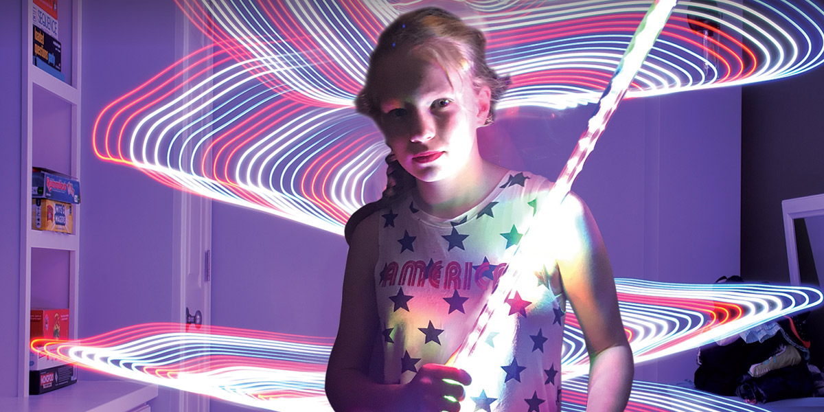
The purpose of this article is to explain in detail how you can build a low cost (<$100) microprocessor-controlled LED light saber that provides as much or more capabilities than professional light wands. Figure 1 is an example of the light saber configured for alternating red, green, and blue patterns.
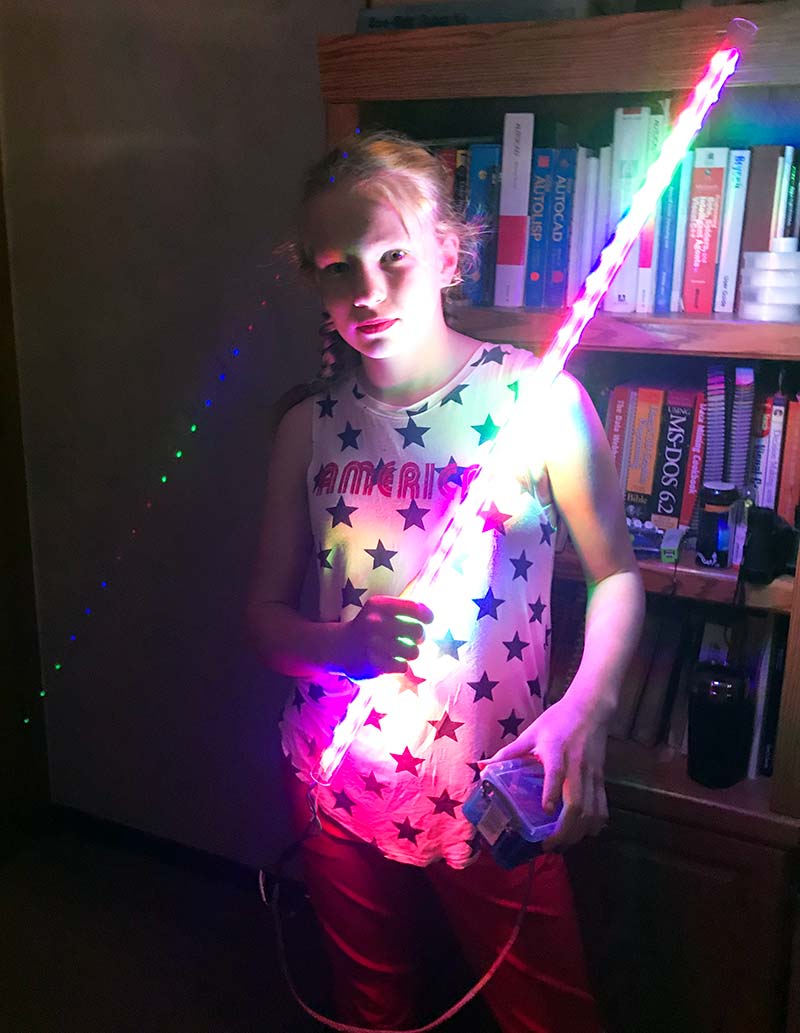
FIGURE 1. Microprocessor-controlled LED light saber.
Figure 2 is an example of a light graffiti photograph taken using the LED light saber.
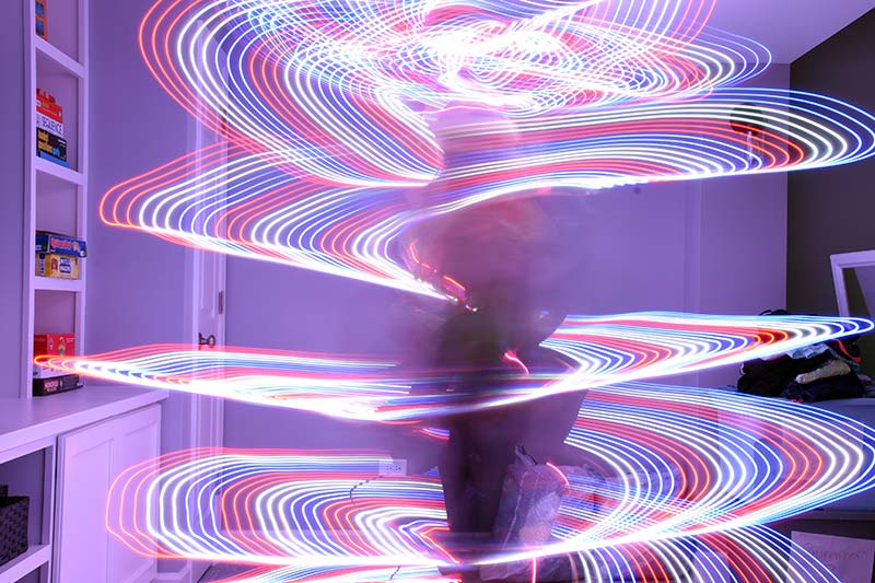
FIGURE 2. Example of light graffiti using LED light saber.
Experience Level Required
The assembly of the light saber requires basic electric circuit skills, wiring, soldering, and shrink wrapping. However, programming a Raspberry Pi is a bit more challenging.
If you’re a novice to the RaspPi environment, I highly recommend that you buy a complete Pi starter kit (board, HDMI/USB cable adapters, NOOBS formatted SD card, power supply, case) and experiment with Python programming before attempting to build the light saber.
There are numerous resources and books available to teach you how to configure and program a Raspberry Pi. (Check out the ad on page 59 for the books that are available in the JunkBox store.)
Bill of Materials
The basic processor board for the light saber is the Raspberry Pi Zero W. The board (without the SD card) can be purchased for as little as $6. You might consider purchasing a starter kit that includes HDMI and USB cables to create a test environment for development of additional light patterns.
Figures 3a and 3b are photos of my development environment for the light saber. Note that I have a small LED strip associated with it. When I bought the LPD8806 LED strip, I ordered three meters (96 LEDs) and then cut the strip down to 56 for use in the light saber. The remaining strip I repurposed for several projects, including my light saber test bed.
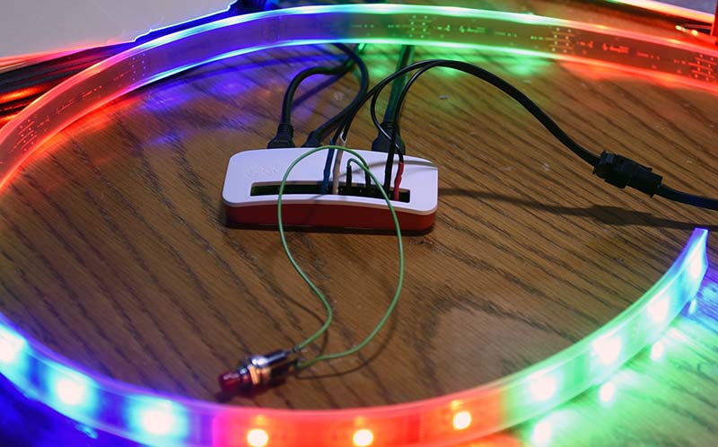
FIGURES 3A and 3B. Development system.
The development environment includes a mini HDMI and a micro USB connector, as well as a wall wart micro USB power. These connect to my monitor, keyboard, and mouse to allow editing of the Python script and the testing of various LED patterns, as well as making modifications to the Linux/Raspbian OS.
The secret to the flexibility and capability of the light saber is the LPD8806 LED strip. Each of the individual LEDs has a red, green, and blue component that can be set individually to 128 different settings, yielding a large number (>1,000,000) of possible colors and 100 different settings for brightness.In addition, the SPI interface is running at 1.2 MHz which allows the Raspberry Pi to rapidly change the color of each LED and implement dynamically changing/moving patterns.
In my prototype, I only implemented static patterns, thereby creating lots of future development opportunities.
Battery Life
At full brightness, each LED draws about four milliamps (mA). With 56 LEDs in my light saber, 56 * 4 mA = 224 mA. The RaspPi Zero W current draw varies depending on what peripherals are in use. A conservative estimate would be 240 mA.
If we assume a fully charged (new) 2,600 mAh battery, the theoretical life would be 2,600 mAh/(224 + 240) mA = 5.6 hours on a single charge. Real world battery life will be less than that but suffice it to say, you’ll get at least two hours of use on a single charge.
Speaking of batteries, the original USB-A current standard was 250 mA — clearly not enough to provide power to the LEDs and the Pi. The choice of battery is mostly a decision of physical size (fit in the case) vs. amp-hour capacity. However, make sure to get one that can supply enough power; preferably one amp.
Assembly/Wiring
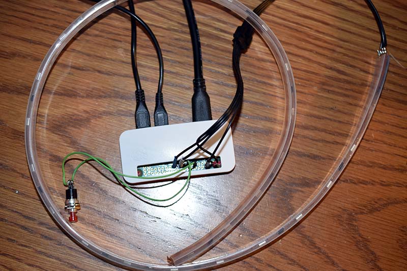
Figure 4 and Figure 5 are close-ups of the assembled light saber and battery/control box. There are four wires connecting the control box to the light saber: 5V, GND, and the SPI signals SCLK and MOSI (no return signal MISO from the lights). On the LPD8806 LED strip, they’re labelled +5, GND, CI, and DI. The length of the wires should be kept as short as possible to insure proper operation of the LED strips.
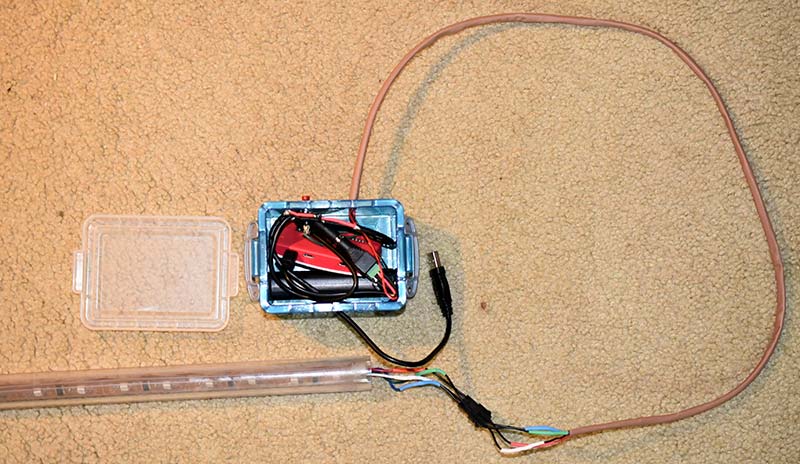
FIGURE 4. Light saber and control box.
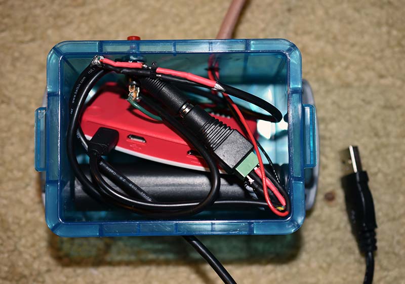
FIGURE 5. Control box close-up.
I’ve tried various lengths and found that 2.5 ft is the max. Figure 6 is a schematic of the entire circuit.
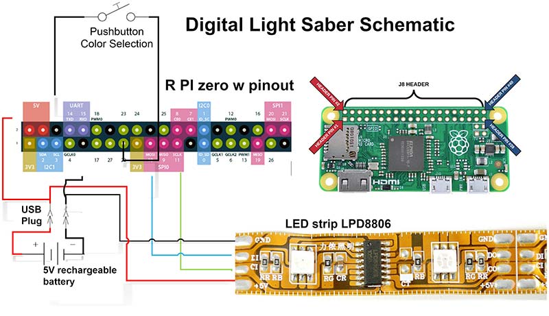
FIGURE 6. Saber schematic.
The assembly of the control box depends on the size of the battery and orientation of the RaspPi. As you can see from the photo, my box was not quite big enough for the Pi to fit lengthwise. For future development, I plan to 3D print a custom box with pre-built holes for the pushbutton, USB, and light saber cabling.
When drilling the holes for the battery USB plug, don’t forget to enlarge it enough to allow for a charging cable to be plugged in as well.
One of the assembly challenges is how to power the Pi. The “correct way” is to use a micro USB plug as you can see in Figure 5. I couldn’t find unterminated micro USB plugs, so I had to cut a standard cable in half and manually connect the USB power (red) and ground (black) wires to the battery. This is not only challenging because the USB wires are small, but the plug sticks out from the case.
I’ve tried powering the RaspPi directly from the 5V pins on the board to the battery. It seems to work fine, but this does bypass the protection of the “poly fuse” on the USB 5V input. I currently use the USB plug to turn on the system. However, you could install an on/off switch for a more professional look and feel.
As for the light saber itself, I merely folded the 56 LED strip in half and carefully slid it into the tube to within about 1” of the end of the plastic tube. The 3/4” inside diameter is just large enough for the strip to fit but small enough that once the strip is fully inserted, it will stay in place.
Once you’ve assembled the control box and light saber and charged the battery, plug in the USB cable. It will take about 40 seconds for the Pi to boot up.
Software/Programming
Communicating with the LPD8806 LED strips is relatively complex. The string of LEDs is treated like a large shift register that is chained down the strip. Fortunately, the Adafruit documentation is extensive and the GitHub library includes several examples and a library to import (https://github.com/adammhaile/RPi-LPD8806).
Once you’ve downloaded the library and unzipped it to your /home/pi directory, you have all the support libraries that you need. You will next enable the SPI interface on your Raspberry Pi by running:
sudo raspi-config
then select Interfacing Options -> SPI Enable -> Yes.
Once you have that installed, open a Terminal session, change the directory to the RPI-LPD8806-master directory, and type the following command:
python example.py
You should see some amazing patterns and colors; you are now ready to try your own programming to vary the light patterns.
This is a Python code snippet from the main light saber program:
import RPi.GPIO as GPIO
import time
from bootstrap import *
…
colors = [
(0.0,0.0,255.0), #Blue = 0
(0.0,255.0,0.0), #Green = 1
(255.0,255.0,0.0), #Yellow = 2
(255.0,255.0,255.0), #White = 3
(255.0,0.0,0.0), #Red = 4
(0.0,255.0,255.0), #Cyan = 5
(255.0,0.0,255.0), #Magenta= 6
(255.0,128.0,0), #Orange = 7
(255.0,64.0,0.0), #Pink = 8
(255.0,64.0,128.0), #Purple = 9
]
maxcolor = 12 #max # light states
def scheme_on():
global scheme_ndx
r, g, b = colors[scheme_ndx]
level=.99
led.fill(Color(r, g, b, level))
led.update()
time.sleep(.05)
…
def rgbalt():
for i in range(1,4):
ioff = (i-1)*3*3
led.fillRGB(255.0,0.0,0.0,1+ioff,3+ioff)
led.update()
led.fillRGB(0.0,255.0,0.0,4+ioff,6+ioff)
led.update()
led.fillRGB(0.0,0.0,255.0,7+ioff,9+ioff)
led.update()
def rwbalt():
for i in range(1,4):
ioff = (i-1)*3*3
led.fillRGB(255.0,0.0,0.0,1+ioff,3+ioff)
led.update()
led.fillRGB(255.0,255.0,255.0,4+ioff,6+ioff)
led.update()
led.fillRGB(0.0,0.0,255.0,7+ioff,9+ioff)
led.update()
schemes = {‘0’:scheme_off,’1’:scheme_on,’2’:scheme_on,’3’:scheme_on,’4’:scheme_on,’5’:scheme_on,’6’:scheme_on,’7’:scheme_on,’8’:scheme_on,’9’:scheme_on,’10’:rgbalt,’11’:rwbalt}
The “from bootstrap import *” statement is all that is necessary to include the entire library to interface to the LED strip. The “colors” structure defines the 10 single color patterns currently implemented. All the LED interfacing is done in the led.fill() function.
In the main loop, the scheme_ndx is incremented whenever the pushbutton is pressed (GPio Pin 22->0). The first 10 presses will call the function “scheme_on” with the corresponding color. For scheme 10 and 11, the functions rgbalt (alternate red, green, blue) and rwbalt (alternate red, white, blue) will be executed. Once the last scheme is displayed, the scheme will repeat the color sequence.
Headless/Autostart
Figure 7 is the screenshot of the RaspPI development environment. On the left side, you’ll see the Python editor with a portion of the “light_graffiti_v1.py” software loaded. The upper right-hand window is the tree directory “led_lpd8808.”
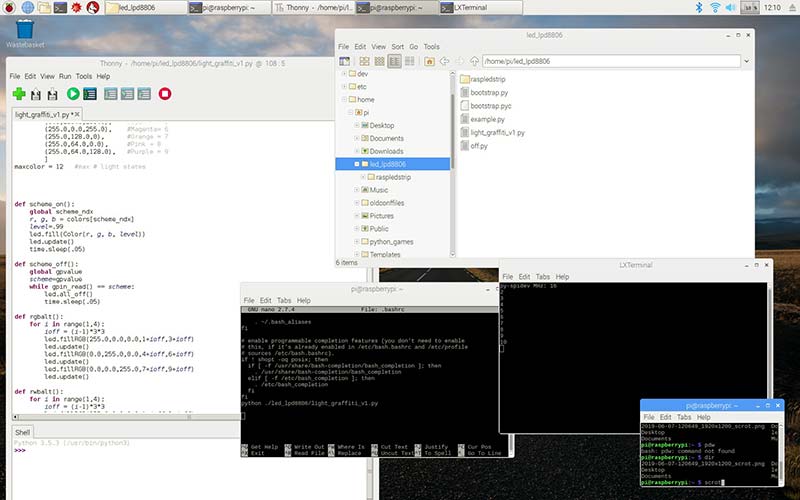
FIGURE 7. Screenshot of development environment.
To build a “headless” (no monitor, keyboard, mouse) version, you need to place the following command in the .bashrc file that exists in your home directory /home/pi (bottom center window — nano text editor):
python ./led_lpd8806/light_graffiti_v1.py
This statement starts the Python interpreter using the light saber program located in the subdirectory below my home directory.
The .bashrc file is run upon boot (and whenever a terminal session is initiated), so your light saber Python program will autostart whenever you plug in your USB cable (remember 40 seconds to boot up).
Photography/Actions
As in dancing, the choreography of the movement in light graffiti is as important as the subject itself. Back in Figure 2, my granddaughter, Julia started with her back to the camera and the light saber almost touching the ground. She made three complete revolutions while slowly raising the light saber as she rotated during the 30 second exposure window.
At the end of the rotations, she then raised the light saber over her head and continued to rotate it vertically. In Figure 8, she changed the color to red and held the light saber vertically in front of her slowly rotating the light saber in a circular motion.
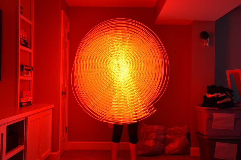
FIGURE 8. Light graffiti circular.
In Figure 9, she used the light saber to illuminate the “canvas” by placing it on the floor in front of her and then spelled out her name using a flashlight.
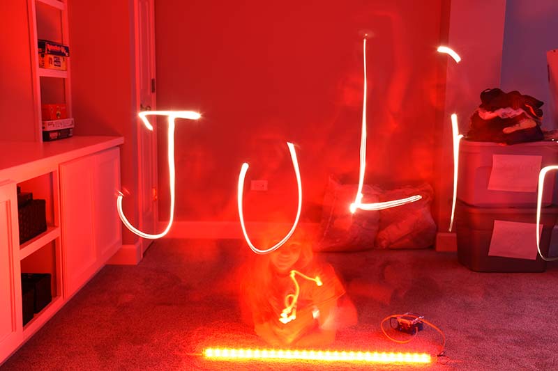
FIGURE 9. Light graffiti name spelled.
In Figure 10, I stood behind her while she rotated the light saber in a semicircular motion (“angel wings”) as she used a flashlight to draw a smiley face. You can see from this limited selection of images the almost unlimited number of light patterns/colors/shapes that can be created.
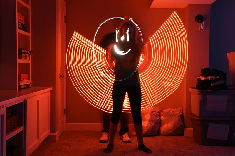
FIGURE 10. Light graffiti angel wings.
Future Development
As we’ve already discussed, there are several possible improvements to the light saber. First, the control box could be 3D printed so that the Pi and battery fit snugly with all the wiring and pushbutton holes built into the case.
For a more challenging 3D print, I believe that a handle could be attached to the plastic tube that could house the battery and RaspPi, thus eliminating entirely the need for a control box.
Also as mentioned, we have only begun to experiment with the various light colors, brightness, patterns, and movements possible. It’ll be interesting to see what other patterns readers/builders come up with.
Finally, the Raspberry Pi Zero W includes Wi-Fi capability. So, it’s quite possible for the light saber to be remotely controlled from a computer or even a smartphone.
Conclusion
I have used these LEDs in several “work” projects including a simulated demonstration of electrons flowing at a large trade show/conference. The Raspberry Pi is my “go to” computer for almost all my embedded microprocessor projects.
Using tools like these for both work and hobbies makes life much more fun and interesting. Being able to discuss and experiment with math, physics, electronics, computers, and photography with my grandkids ... priceless. NV
Parts List
| Quantity |
Item Description |
Approximate Cost |
Possible Source |
| 1 |
Raspberry Pi Kit, Pi Zero W |
$6-$75 |
Amazon, Adafruit, Raspberry Pi Org |
| 1 |
36” clear plastic tube 3/4” ID 1” OD |
$10 |
US Plastic Corp |
| 32-64 |
LPD8806 weatherproof LED |
$30-$60 |
Adafruit |
| 1 |
Portable USB battery 2,600 mAh |
$10 |
Inland USB-A power bank |
| 1 |
Plastic box |
$6 |
Office Depot |
| 1 |
Sub mini pushbutton |
$5 |
Amazon |
| |
Miscellaneous wires/ jumpers/connectors |
|
Adafruit, Microcenter, Amazon |
| 1 |
NOOBS formatted 16 GB SD card |
$15 |
Amazon |
Resources
Light painting
https://en.wikipedia.org/wiki/Light_painting
Light graffiti examples
http://lightbombing.com
Raspberry Pi tutorials
https://tutorials-raspberrypi.com
Using .bashrc
https://cloudzy.com/knowledge-base/linux-bashrc/
GitHub library
https://github.com/adammhaile/RPi-LPD8806
Downloads
What’s in the zip?
Source Code