Ever try to read a resistor on your DMM (digital multimeter) less than one ohm? It’s very difficult as the result fluxates wildly due to the lead’s resistances and the methods that DMMs use.
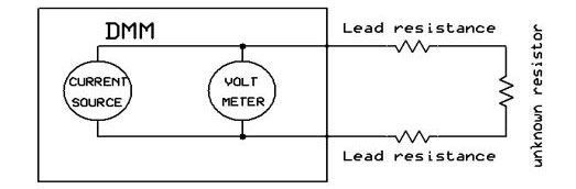
Two-lead meter.

What is actually happening is that the current source is in direct contact with the DMM, so the current goes through the test leads and adds their resistances to the measurement. This is known as two-lead measurement.
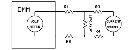
Four-lead Kelvin meter.
Notice that with a four-lead meter no amperage flows through R1 and R2 due to the high resistance of the meter. The current flowing through leads R3 and R4 must be the same as what’s flowing through the unknown resistor. Therefore:

If you have a constant current source unit and an accurate DMM, you can make your own using the four-wire circuit above and then performing the calculations. However, most of us don’t have a constant current source. Enter the Kelvin four-lead ohmmeter I’ll discuss here.
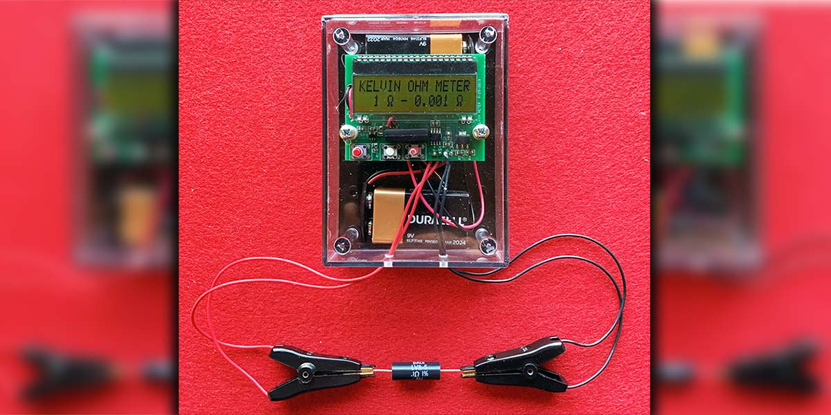
What I’ve done is put everything in one box, making it quite portable. It uses two nine volt batteries: one for the meter and the other for the constant current source. The normal DMM uses 1 mA to measure low resistances. With this meter, the constant current source provides ≈ 200 mA which increases the current source 200 times.
The name of the meter came from Lord Kelvin (William Thomson), a Scotsman who lived from 1824-1907. He was one of the most eminent scientists of the nineteenth century and is best known today for inventing the international system of absolute temperature that bears his name. Kelvin adapted part of the “Wheatstone Bridge” for his meter.
If you look at the schematic, you’ll see that the power supply to the meter and the constant current source are isolated.
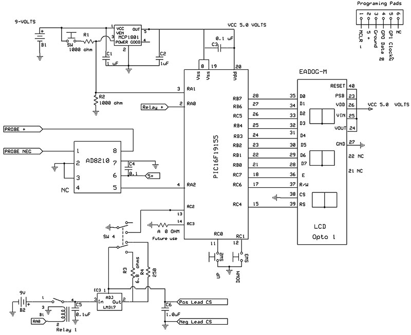
Schematic.
A relay is used to turn on the battery to the constant current supply. Two nine volt batteries are used to power the unit. A 5.0 volt voltage regulator powers the microprocessor, AD8210, and the LCD.
The “turn on, turn off” circuit is interesting as it uses a nine volt source and a five volt regulator with a shut down function. R1 and R2 (1K ea) are a voltage divider. The SHDN is normally biased to ground.
When S1 is pushed, it applies ≈ 4.5 volts to the SHDN. The microprocessor is then turned on and PortA,0 applies five volts to the SHDN keeping it on until the WDT (watchdog timer) brings PortA,0 to ground.
I used an AD8210 made by Analog Devices. This is a high voltage/bidirectional current shunt monitor. It’s a single-supply, difference amplifier ideal for amplifying small differential voltages in the presence of large common-mode voltages. It also amplifies the voltage 20 times.
I chose to use a Microchip PIC16F19155 as it has a 12-bit analog-to-digital converter (ADC) with a 4.096 volt voltage reference which allows each bit to measure:
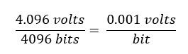
This gives us a range 1 ohm to .001 ohms (1 mΩ).
CALCULATION
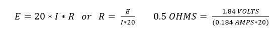
Ohm’s Law comes into play once again. The voltage drop across a resistor depends on the amount of amperage flowing through it. In this case, the current is kept constant using an LM317 adjustable linear voltage regulator and a 6.8 ohm resistor. A 1206 6.8 ohm resistor was used due to the amount of power it uses. This calculates as:

The AD8210 op-amp multiplies the voltage drop across by 20. So, if the ADC is measuring 1.84 volts, the calculation will be as follows:
All the math is computed in the microprocessor using a division algorithm and then converted from hexadecimal to decimal. It’s then displayed using an LCD.
I’ve included a 1% resistor in the unit for calibration, allowing for correction of any offset caused by the op-amp. The calibration factors are stored in the microprocessor’s SRAM memory and are retrieved each time the unit is turned on.
Adafruit has two-wire Kelvin test clips which I used to provide the contacts. Each one is connected to the current source and the other to the DMM probe. Two of these are needed.
As an afterthought, I added a switch so that you can also measure 38 ohms to 0.01 ohms. The 250 ohm resistor provides 5 mA for measurement. When using the one ohm setting, the 200 mA puts quite a load on the nine volt battery, so I pulsed the relay to turn for ≈ 1 ms.
It’s then turned off and the display remains on for ≈ .7 seconds. NOTE: For the meter to work properly, both connectors of each clip must be shorted together.
CONSTRUCTION
Find the template for the drilling of the top of the box in the downloads. Cut out the template and paste the template to the top of a box using a glue stick. Drill the five holes as indicated. Remove the template using hot water. Using a 6-32 tap, tap the two holes inline with the switches on the board.
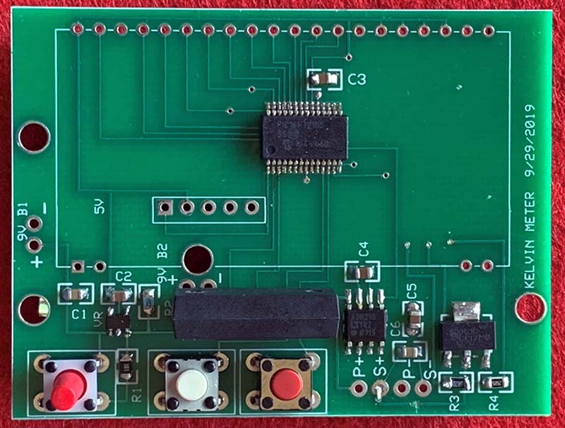
Top view.
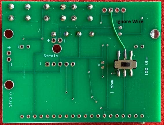
Bottom view.
Some of the parts on the circuit boards are surface-mount. Don’t panic! It’s easier than you think. Just make sure you have solder braid (0.635 mm). I also recommend using 90-degree forceps.
Turn the board face up with the date facing you. Solder C1, C2, C6, C3, C4, and C5 for practice. Solder R1, R2, R3, and R4. Note the location of pin 1. Often, it’s just a small notch to the left or a dimple over the pin. Solder IC1, IC2, IC3, and the VR.
Don’t feel bad if you get solder bridges. I often just flood the microprocessor with solder and then remove the excess using solder braid. I’m a firm believer in using solder flux.
Solder the three momentary switches. The long post goes to SW1. Pass the two leads from the battery holders through their respective strain holes from the bottom of the board and solder to their pads, noting red to + black to -. Turn the board over and solder in SW4.
Don’ worry about the “A” area; it’s for future use. Turn the board over again. Before soldering the LCD, place the LCD into its pads and push for contact.
Turn on the unit and make sure it’s displaying. If not, check for solder bridges or cold solder joints on the micro. If it’s working, solder in the LCD over the components. Remove any safety tape.
Solder the two red wires to S+ and P+. Solder the two black wires to S- and P-. Pass them through the two holes in the bottom of the box.
Mount the board to the top of the box using two 6-32 1/2” screws and two 3/16” spacers.
The board files and the schematic were generated using Express PCB free software (go to www.expresspcb.com). These files are available in the downloads, along with the assembly file for the microprocessor.
USING THE METER
Place some double-sided tape onto the batteries and place them on the bottom of the box. Connect the nine volt battery clips.
Make sure the slide switch (SW4) is on 1 ohm. Push the “ON” switch. The LCD should display what the slide switch is set on.
Short the clips by attaching them to the same side of the resistor. Adjust the zero reading by using a paper clip and pressing the “UP” or “DOWN” momentary switches. When holding down the switches, the display will show “Calibration.” When released, it will show the measurement.
Connect the clips across the 0.1 ohm 1% resistor. (Both contacts of each Kelvin clip must contact the resistor.) Read the results.
For small components and traces, try using “map pins” on the Kelvin leads. Also keep in mind that on “one ohm,” you have 200 mA flowing. The meter will shut off after 128 seconds.
Stay tuned for an article to add a low resistance probe to our Kelvin meter. NV
Parts List
| Battery clips |
9 volt |
2 |
616-6056301 |
Mouser |
| Chassis |
4.38 x 3.25 x 1.40" |
1 |
635-032C |
Mouser |
| C1-C2-C6 |
1.0 µF 805 |
3 |
963-UMF212B7105KGHT |
Mouser |
| C3-C4-C5 |
0.1 µF 805 |
3 |
963-LMF212B7104KGHT |
Mouser |
| IC1 |
PIC16F19155 |
1 |
579-PIC16F19155-I/SS |
Mouser |
| IC2 |
AD8210 current amp |
1 |
584-AD8210YRZ-R7 |
Mouser |
| IC3 |
LM317 |
1 |
863-NCV317MBSTT3G |
Mouser |
| OPTO |
Dog Reflective 162LA |
1 |
790-EADOGM162LA |
Mouser |
| Probe |
Adafruit clips |
2 |
3313 |
Adafruit |
| R1-R2 |
1.0K 805 |
2 |
603-RT1206FRE076R8L |
Mouser |
| R3 |
6.8 1% 1206 |
1 |
APC0805B250RN |
Mouser |
| R4 |
250 1% 805 |
1 |
734403 |
Mouser |
| Relay |
5 volt SPST NO |
1 |
934-HE3621A0500 |
Mouser |
| Screws |
6-32 1/2” |
2 |
2094434 |
Jameco |
| Standoffs |
.25 x .375 6-32 |
2 |
1548B |
Mouser |
| Switch 1 |
NO 13 mm momentary |
1 |
612-TL1105D-250 |
Mouser |
| Switch 2-3 |
NO 2 mm momentary |
2 |
612-TL1105F100Q |
Mouser |
| Switch 4 |
DPDT surface-mount |
1 |
611-JS202011SCQN |
Mouser |
| VR |
5.0 volt SM with switch |
1 |
MCP1801T-5002I/OT |
Mouser |
| Wire black |
8” #24 |
2 |
734411 |
Jameco |
| Wire red |
8” #24 |
2 |
734403 |
Jameco |
Downloads
What’s In The Zip?
Kelvin Meter Template
Code
PCB File
Schematic