I’m not sure if it’s absent mindedness or just old age, but sometimes I’ll forget to close the food freezer lid after shopping for groceries. Even my daughter (R.Ph., Pharm.D., RN, BSN) has occasionally left the freezer open. With food prices seemingly going up every three days, there’s really no good time to lose a pile of food because of a simple mistake. This article describes my solution to the freezer problem.
HOW IT WORKS
Figure 1 shows the complete freezer alarm circuit. IC1 (555) is configured as a basic “one-shot.”
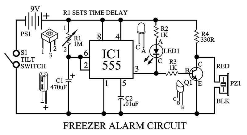
FIGURE 1.
In other words, once the circuit is activated (tilt switch on), the output voltage on pin 3 of IC1 will remain high for a set period of time.
Notice that both the base of the transistor (Q1) and the cathode side of the LED will be high. This shuts off the LED and turns on the transistor. The alarm buzzer (PZ1) will see a low at the collector of Q1 and remain off until pin 3 of IC1 goes low.
So, at start-up (freezer lid open), we have the LED and the alarm off for a period of time.
The time delay is generated by the combination of the resistance of R1 (potentiometer) and the 470 µF capacitor (C1).
Now, since IC1 pin 2 (trigger) and 6 (threshold) are tied to the junction of R1/C1, the voltage at pin 2 is held low because capacitor C1 (470 µF) is discharged. As C1 charges through R1, the voltage at pin 2 rises until pin 6 (threshold) reaches 2/3 of the 9V power supply voltage.
Once the time delay ends, pin 3 of IC1 will go low. This low will turn on the LED and turn off the transistor Q1 (NPN). With the transistor turned off, the alarm will see a high at the collector (C) and begin melting your ear drums.
To deactivate the freezer alarm just close the freezer lid and it will reset the time delay. In other words, the tilt switch will cut off the power (9V) to the circuit.
A nice feature of the freezer alarm is the fact that battery consumption does not start until the tilt switch is activated (freezer lid open). So, the 9V battery should last a long time.
The LED was added to the circuit just as a visual indicator for testing circuit operation.
DELAY! DELAY! DELAY!
You can also adjust the time the freezer lid stays open before the alarm triggers (see Figure 2). Just make sure to set the time delay for R1 (pot) before soldering the potentiometer into your PCB (printed circuit board).
| TIME DELAY |
SET POT (R1) TO: |
C1 |
| 1 min 30 sec |
200K |
470 µF |
| 2 min 45 sec |
300K |
470 µF |
| 3 min 30 sec |
400K |
470 µF |
| 3 min 45 sec |
500K |
470 µF |
| 4 min 45 sec |
600K |
470 µF |
| 5 min 45 sec |
700K |
470 µF |
| 6 min 30 sec |
800K |
470 µF |
| 7 min 30 sec |
900K |
470 µF |
| 8 min |
985K |
470 µF |
FIGURE 2.
CIRCUIT CONSTRUCTION
If you’re planning to use perfboard as a platform for the freezer alarm circuit, let me suggest a much better PCB.
Figure 3 shows the PCB I found online that makes it so much easier to connect and solder components.
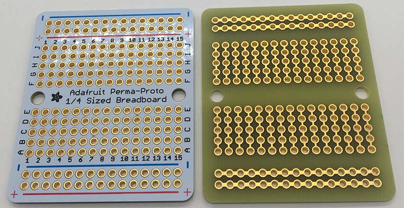
FIGURE 3.
First, all of the 210 holes on the board are plated through holes. Secondly, there are 15 columns of holes across the board. All the holes in each column are connected together (traces). This makes it much easier to connect multiple component leads to one IC pin.
Power (+) and ground (-) holes run horizontally across the top and bottom of the board.
Figure 4 shows how I arranged the components on the PCB. Feel free to lay out the components on the board as you please.
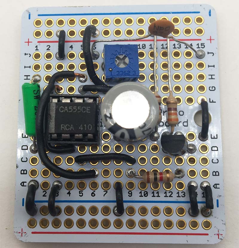
FIGURE 4.
Please note that in order for the tilt switch (S1) to operate correctly, it must be mounted on an angle as shown in Figure 4a.
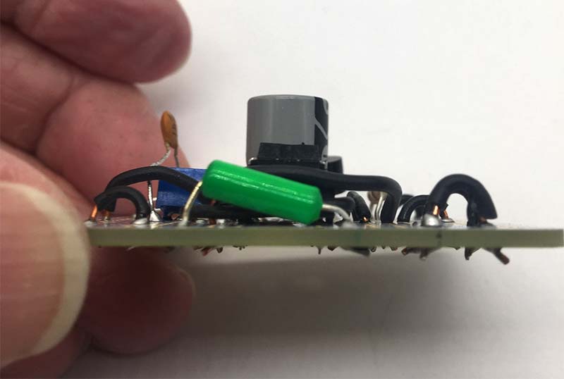
FIGURE 4A.
The angle can be set with a tape measure. The height from the top surface of the PCB to the highest point on the tilt switch is exactly 1/4 inch.
Also watch that you ordinate the tilt switch (front to back of the PCB) so that it’s in the off position when the PCB is level. Take your ohmmeter and connect the meter leads to the ends of the tilt switch. There are only two possible meter readings — 000 on the meter display means the switch is on. A blank display (infinity) means the switch is open (off).
Figure 5 shows the LED, battery clip, and the piezoelectric buzzer attached to the PCB.
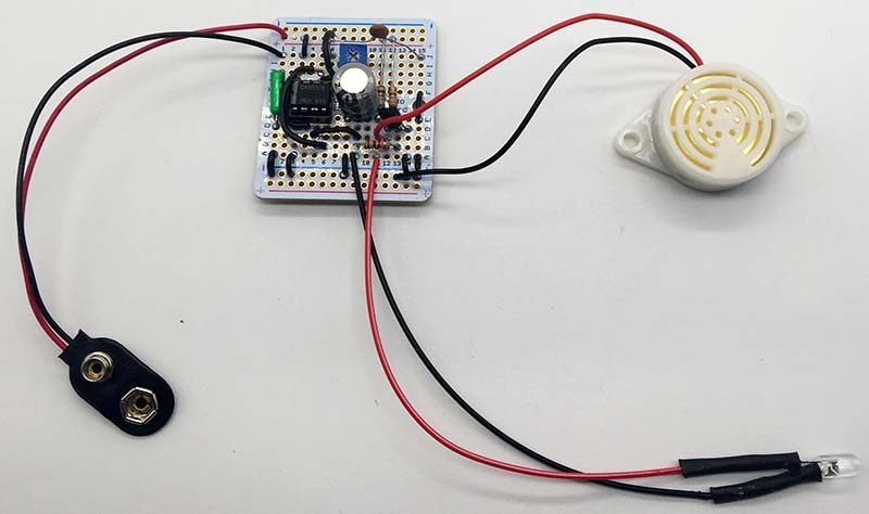
FIGURE 5.
I designed and printed an enclosure for the freezer alarm on my 3D printer (see Figure 6).
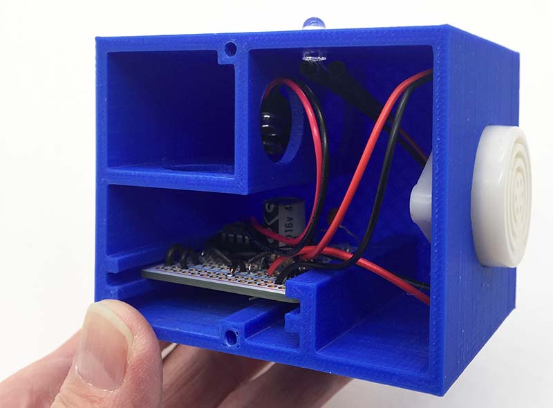
FIGURE 6.
If you don’t have a 3D printer, any small box enclosure you have available should work just fine.
The final construction procedure is to add four small magnets to the bottom of the enclosure. Since most food freezer lids are metal, the magnets will make it easy to attach and remove the alarm from the lid.
The completed project is shown in Figure 7.
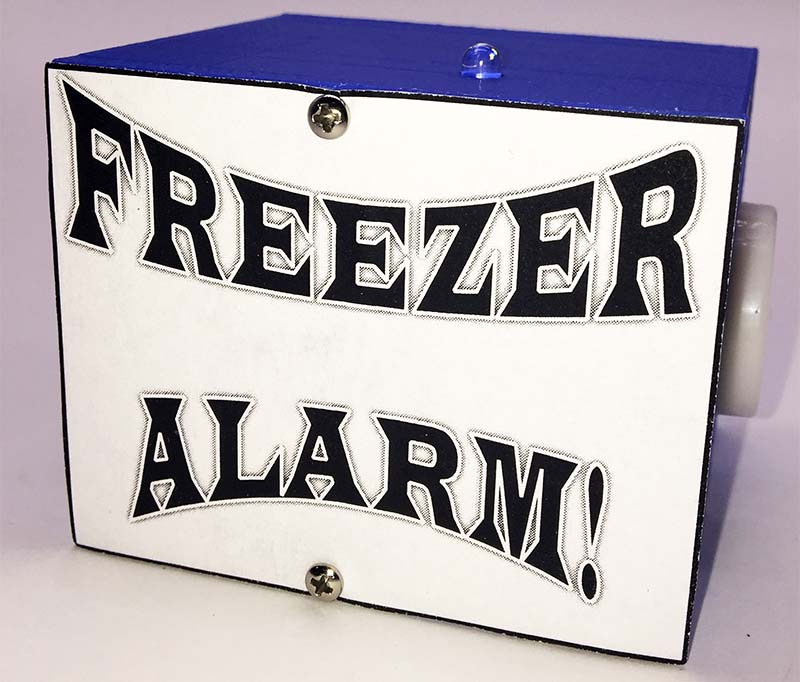
FIGURE 7.
FINAL THOUGHTS
It’s not required, but you might want to use an IC socket for IC1. After soldering all the components to the PCB, I couldn’t figure out why my circuit wasn’t working.
After I plucked out a few more hairs on my head, I decided to try replacing IC1 (555). Well, that did it! Luckily, I installed an IC socket for IC1. Otherwise, it would have been a lot harder to remove the chip from the PCB.
Finally, the hole in the enclosure for mounting the piezoelectric buzzer must be loose enough as to not crush the buzzer housing. If it’s too tight, the sound emanating from the alarm will be diminished. NV
Parts List
| QTY |
ITEM |
DESCRIPTION |
PART# |
SOURCE |
| 1 |
R1 |
Potentiometer, 1M |
3362 |
Amazon |
| 2 |
|
Resistors, 1K, 1/4W |
791-RC1/4-102JB |
Mouser |
| 1 |
R4 |
Resistor, 330 ohms, 1/4W |
660-CFS1/4C331J |
Mouser |
| 1 |
C1 |
Capacitor, 470 µF, Electrolytic |
EEU-FR1E471B |
Mouser |
| 1 |
C2 |
Capacitor, .01 µF |
594-D103Z25Z5VF63L6R |
Mouser |
| 1 |
Q1 |
Transistor, NPN, 2N2222A |
610-PN2222A |
Mouser |
| 1 |
IC1 |
555 Timer |
595-NE555P |
Mouser |
| 1 |
|
IC Socket, Two Rows, Eight-position |
575-144308 |
Mouser |
| 1 |
LED1 |
Through Hole, Red, Water-clear Dome, 640 nm, 5 mm Diameter |
604WP1503SRC/F |
Mouser |
| 1 |
PZ1 |
Piezoelectric Buzzer, 3-24 VDC, Continuous Beep, White, Industrial SFM-27 |
OD2017101303UP |
Amazon |
| 1 |
PCB |
Printed Circuit Board, Three Pack |
ADA589 |
Amazon |
| 1 |
S1 |
Tilt Switch, Metal Ball |
SW200D |
Amazon |
| 1 |
PS1 |
9V Battery |
|
Local Store |
| 1 |
|
Battery Snaps |
121-0526/I-GR |
Mouser |
| 4 |
|
Magnets |
|
Lowes |