I decided to make an electronic musical toy as a Christmas gift for my young son. I browsed the Web looking for inspiration and found the stylophone: a miniature analog stylus-operated keyboard that was invented in 1967 by Brian Jarvis. I based my own design on this; in fact, I replaced short keys with long ones, thus creating a kind of writing pad. Indeed, you can write characters and even words on this pad, and every character has its own ‘sound portrait.’
I think my stylophone can be useful for children beginning to write. It makes the learning process fun and helps kids better remember each character thanks to the unique sounds.
The Circuit
The circuit shown in Figure 1 is basically an astable oscillator built with an IC 555; you can find a description of how this circuit works if it seems unfamiliar on [url=http://www.electronics-tutorials.com]http://www.electronics-tutorials.com[/url].
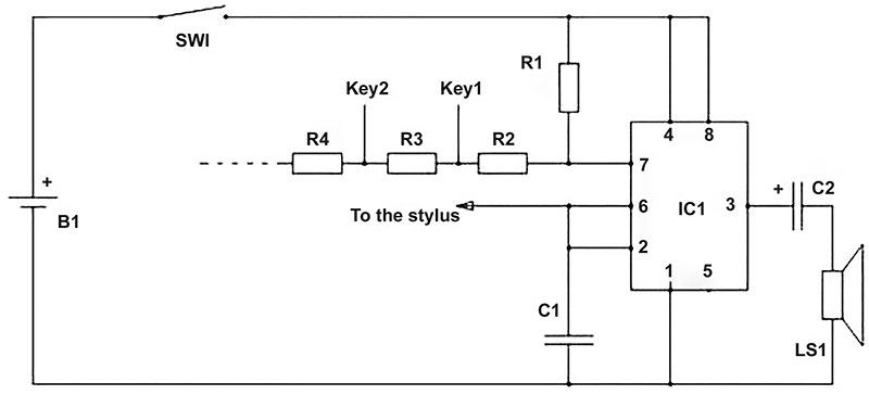
FIGURE 1. The circuit.
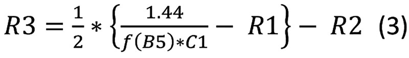
The frequency of the oscillations depends on the values of R1, R2, and C1, and is calculated as:
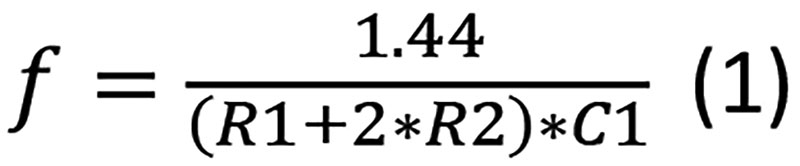
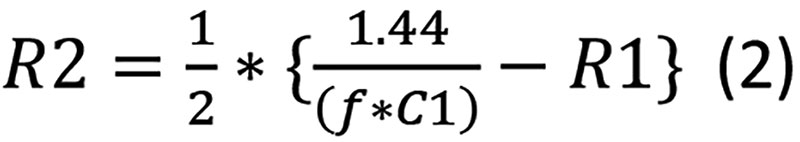
Therefore, if you want to change the frequency, you should change either R or C. When playing a stylophone, you change R2 to change the frequency of the sound. I transformed the formula (1) to separate R2:
The range of my device includes 12 notes: from C6 (chosen at will) to C5#/D5b; refer to Table 1.
| C#5/Db5 |
554.37 |
| D5 |
587.33 |
| D#5/Eb5 |
622.25 |
| E5 |
659.25 |
| F5 |
698.46 |
| F#5/Gb5 |
739.99 |
| G5 |
783.99 |
| G#5/Ab5 |
830.61 |
| A5 |
880.00 |
| A#5/Bb5 |
932.33 |
| B5 |
987.77 |
| C6 |
1046.50 |
TABLE 1. A complete table can be found at http://pages.mtu.edu/~suits/notefreqs.html.
The reason for this is purely geometrical. I used an available wooden box (198 x 98 x 31 mm) as the enclosure for the device, and aluminium strips 7 mm wide that I had on hand. Only 12 keys fit in the width of my box.
Let’s take R1 = 10 kΩ and C1 = 100 nF, then R2 for the frequency of C6 (1046.50 Hz) calculated with the formula (2), which is 1,876 ohms (rounded to the whole number). The values for other frequencies can be calculated in the same way; the lower the frequency, the bigger the value of R2.
Let’s add a series of resistors (R3, R4, etc.) to R2; then, as you touch the point ‘Key1’ with the stylus, it’s (R2 + R3) that is connected to the circuit. When you touch the point ‘Key2,’ you connect (R2 + R3 +R4), and so on. Thus, the value of R3 is calculated as:
The other values are calculated in the same way and are indicated in the Parts List. If you need to calculate new values, you can use an online calculator; for example, check out the one from www.ohmslawcalculator.com.
Since the values of the resistors are not standard, it’s necessary to combine a required value from standard ones. However, you might replace permanent resistors with trimmers and establish the required values using an ohmmeter.
The circuit is mounted on a perforated circuit board; connections are made with flexible wires. I suggest placing the components on the plate exactly as they are positioned in the circuit diagram.
Parts List
IC1 = NE555
R1 = 10 kΩ
R2 = 1876Ω
R3 = 411Ω
R4 = 438Ω
R5 = 456Ω
R6 = 482Ω
R7 = 520Ω
R8 = 546Ω
R9 = 570Ω
R10 = 626Ω
R11 = 650Ω
R12 = 690Ω
R13 = 730Ω
All resistors have a power rating of 0.125W.
C1 = 100 nF, ceramic
C2 = 10 mF x 10V, electrolytic
LS1 = speaker with impedance of eight ohms
SW1 = miniature toggle slide switch
B1 = 4 x 1.5V batteries; type AA
Physical Arrangement
You can see the inside of the device in Figures 2 and 3; you’re free to choose you own way to position the components in the box.
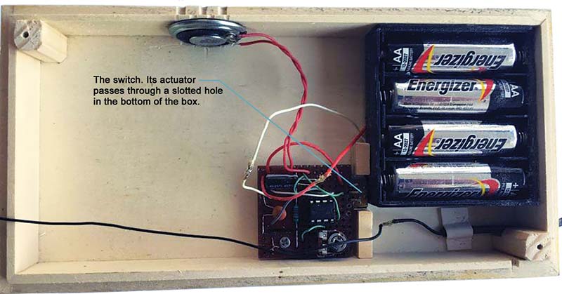
FIGURE 2. Inside view (A).
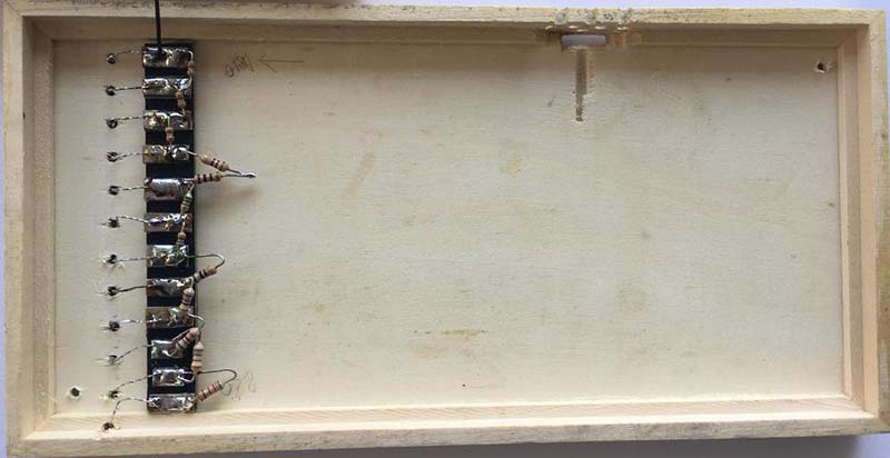
FIGURE 3. Inside view (B).
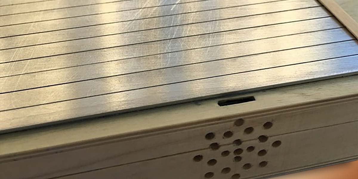
The outside is shown in Figures 4 and 5.

FIGURE 4. Outside view (A).
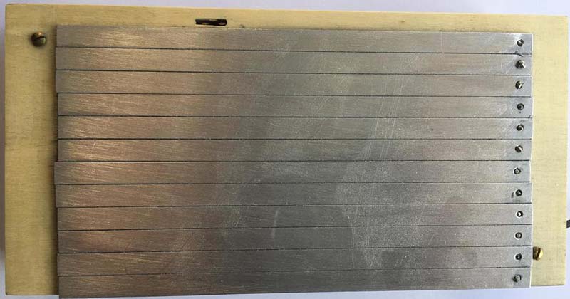
FIGURE 5. Outside view (B).
Keys
I made the keys from an aluminium strip from a cross section sized 7x1 mm. A thin layer of aluminum oxide that is formed on the surface of the keys protects them from further oxidation but does not prevent electrical contact between the keys and the stylus.
A key is shown in Figure 6, whereas Figure 7 explains how to attach wires to the keys.
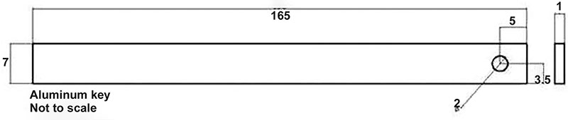
FIGURE 6. Keys.
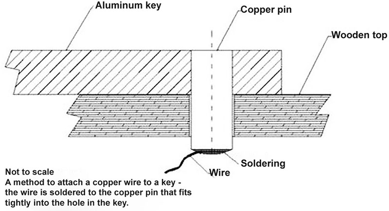
FIGURE 7. Attaching the wire to the key.
Figure 8 shows how to attach the keys to the box. It’s important that the lateral sides of the keys have no chamfers. Otherwise, the stylus would not move smoothly on the surface.
Attaching aluminum keys on the top surface of the box.
Not to scale
1 — Key.
2 — Joint between two keys. A layer of varnish should be put on the lateral sides of the keys to isolate them electrically.
3 — Layer of glue attaching the keys to the surface.
4 — Top surface of the box.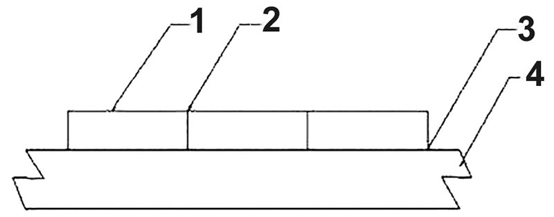
FIGURE 8. Attaching the keys to the box.
Stylus
The stylus shown in Figure 9 is made from a ball point pen that finished its service. The contact that touches the keys is, in fact, a pin of an electrical plug. I soldered a flexible wire to it, put the pin into the pen, and filled the space around the pin with a transparent resin. There is one specific requirement: The end of the pin should be half round and have a smooth surface. This is necessary to avoid scratching the keys.
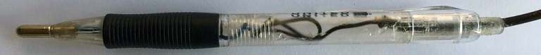
FIGURE 9. Stylus pen.
Instrument and Tools
You’ll need an ohmmeter if you use trimmers to establish required values of R3, R4, etc.; if you wish to get exact notes, you could use a camertone (tuning fork) to tune the device. A soldering iron and wire cutters will be needed to assemble the circuit; a small hacksaw, a drill, and a file are used to make the keys. However, your choice of tools depends mostly on the enclosure that you’ll make for your device; you could 3D-print it as another option.
I hope your “young ones” enjoy this project, no matter how old they are. NV
YouTube Video at https://youtu.be/wUcqAbQAk5w.