I have an MFJ-434 voice keyer that has saved a lot of wear and tear on my vocal cords over the years. It has been a big asset during ham radio contests and when I’ve been calling CQs with reduced power (QRP) transceivers.
One of my new favorite pastimes has been operating QRP radios from remote off-the-grid locations. Most of the time, it’s important to pack only the bare essentials for these mini-DXpeditions. I have never taken the MFJ keyer, primarily due to its size. An “accessory” measuring 6-1/2 x 7 x 2-1/2 inches fills up a lot of backpack. It also weighs a pound and a half. On the other hand, I’m absolutely positive the lack of a keyer has resulted in fewer radio contacts. I always run out of voice before I run out of battery.
Last winter, I was packing a QRP “Go Box” for a trip to Florida. Since that stay was planned to last longer than my normal field trips, I decided to take my MFJ keyer for its first outing. What a difference that keyer made! In less than three months, I worked stations in 31 countries and five continents running a 10 watt transmitter and a dipole antenna!
The enormous number of contacts warranted a closer look at a keyer for shorter field trips. The MFJ-434 has 11 buttons to push, three potentiometers to turn, and two LEDs to show me the keyer is doing what I told it to do. Could I get by with fewer amenities and shrink the size, weight, and power requirements to something more backpack friendly? It was worth an investigation.
The MFJ keyer stores five messages. For field operation, I could live with a single CQ. I found a 20 second record-playback module on eBay for $2.59.
I also found a repeat-cycle timer (variable on and variable off delays) on eBay for $2.38. I could use it to “turn on” the playback message, then turn it “off” for a predetermined period of time before turning it on again.
A relay could be added to key the transmitter’s PTT circuit every time my CQ message was played. The receiver would automatically listen for any replies between messages. (This might actually work!)
With all the major components available from eBay, I drew up the sketch in Figure 1 to put them together.
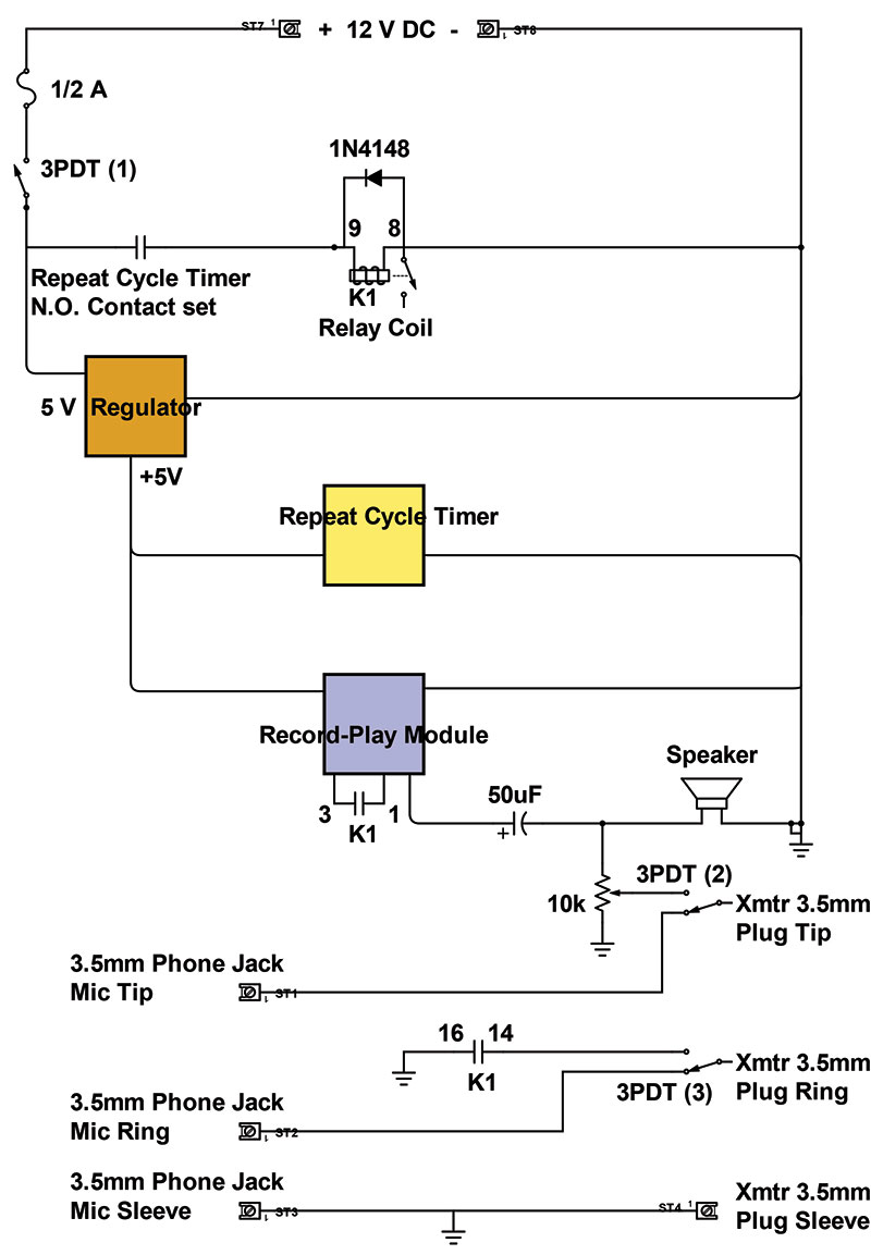
Figure 1.
Description of Circuit Operation
The circuit is simple and straightforward. Although I designed it for use with a Microbitx (µBITX) high-frequency transceiver, it can easily be adapted to any transceiver utilizing a push-to-talk (PTT) microphone. A three-conductor cord connects the two ungrounded contacts of a stereo phone plug to the center pins of a manually operated three-pole double-throw (3PDT) pushbutton switch.
In the Keyer Off position, the switch connects the original PTT microphone to the transceiver’s microphone input jack. In the Keyer On position, the switch connects the output of the Record/Playback Module to the transceiver. The 3PDT switch also controls 12 VDC power to the circuit.
The Record/Playback Module and the Repeat Cycle Timer are both 5 VDC devices. A DC-DC “buck” voltage regulator supplies power to them whenever the keyer is on.
When the pushbutton switch turns the keyer on, the Repeat Cycle Timer is energized and its normally-open output contacts close for a length of time set by the On-Delay potentiometer. At the end of that time period, the N.O. contacts open and remain open for the length of time set by the timer’s Off-Delay potentiometer. At the end of the off-delay, the On-Delay cycle starts over again. These cycles continue to repeat as long as the timer is energized.
The Repeat Cycle Timer’s normally-open output contacts are used to energize K1: a two-pole double-throw relay during the On cycles. Relay (K1) simultaneously keys the transceiver’s PTT circuit and “turns on” the playback module. The recorded message is sent to the transceiver’s microphone input.
R1 is a 10K ohm potentiometer used to set the audio input to the transceiver to around 40-50 mV. I start with R1 at zero and increase microphone input until the transceiver RF output is equal to the output with the microphone.
The recorded message being sent to the transceiver’s mic input can also be heard through the keyer’s speaker.
C1 is used to isolate the Record/Playback DC voltage from the transceiver. D1 is used as a “snubber” to short counter-electromotive voltage spikes from the relay coil to ground.
Construction
I have a decent junk box, so I found the 50 µF capacitor, two-pole double-throw relay, 3.5 mm stereo jack, and a piece of perforated board in the garage.
Even though I had some 3PDT switches on hand, I elected to buy a “Foot Pedal Stomp Switch” from eBay. It will be getting a lot of use and the heavy-duty description appealed to me.
Soon after the last parts arrived, I tack-soldered the individual components together. The concoction shown in Figure 2 worked like a charm.
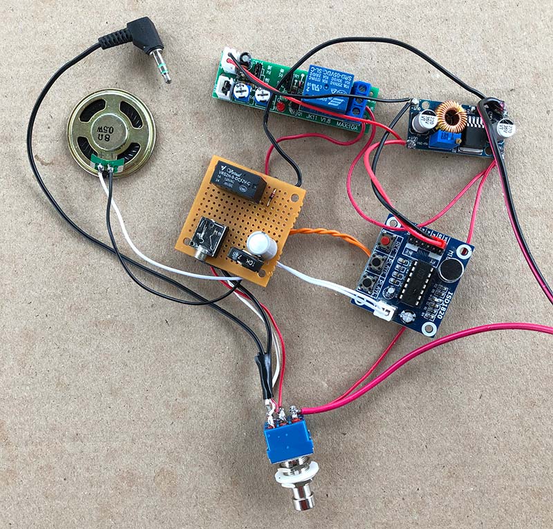
Figure 2.
The only bad news was there was no way I could fit all those boards inside the nice 1-1/2 x 2-1/2 x 5 inch project box I was planning to put them in. A bigger box would be at least a week away from West Virginia.
Fortunately, growing up on a small farm provided me lots of practical experience in the art of innovation. In times like this, I remember my dad telling me: “You can’t be running into town every time you need something. Look around and see what we have that you can make work.”
I found the 2-3/16 x 3 x 3-5/8 inch plastic junction box shown in Figure 3 at our local Lowes store.
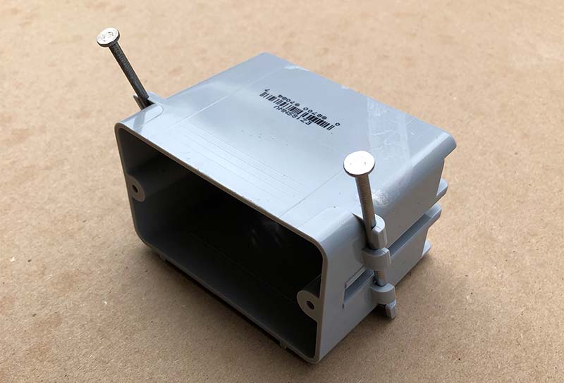
Figure 3.
It could be made to work. A little work with a Dremel tool would be needed to remove the nail brackets intended to hold the box to a wall stud. And, it would still look a lot like an electrical wall box. However, that box would allow me to complete the project on MY time schedule.
Five minutes of Dremel time knocked off both nail brackets. I drilled holes for screws to mount the boards and speaker and sprayed a coat of black paint on the entire junction box. In another hour, the components were secured. The finished product works fine. It doesn’t look terrible, but I’ll probably decide to repackage it at some point in time.
Final Thoughts
Right now, I’m happy to have a single-message CQ keyer that’s only 23% the volume and 1/3 the weight of the commercial keyer it replaces. The only disadvantage I discovered while testing my new keyer is that it pulls 110 mA when calling CQ. That was an unwelcome surprise. The MFJ-434 only sucks 65 mA while calling. Both of them consume 15 mA between calls.
The extra 45 mA won’t be a game breaker for me. The transmit duty cycle should be considerably less than 50% when I’m answering calls. Running the keyer eight hours without any downtime to answer calls will only consume 0.5 ampere-hours of the 12 Ah battery I take to the field. If I run out of battery, it will be because I’m making so many more contacts that my vocal cords will be giving out anyway.
This keyer will also work with Voice Operated Relay (VOX) circuits. It’s a solid-state version of the “Beacon CQer” I built around a cassette tape recorder and a 90-second endless-loop tape back in 1976. That project (described in a 73 Magazine article) inspired a few 6M beacon transmitters that were on-the-air during Solar Cycle 21. Another use for the backpack keyer! NV
PARTS LIST
ISD-1820 Voice Record-Playback Module with Speaker
5V DC Infinite Cycle Delay Timer Relay ON/OFF Switch Module
DC-DC-Step Down Voltage Converter, 5A, 4-38V Input, 3.3-24V Output
3PDT 9-PIN Guitar Effects Stomp Switch Pedal Box Foot Metal Switch
DPDT Relay, 12 VDC Coil, Virtual P/N VRS2H-S-DC12V-C (or equal)
1N4148 Switching Diode 75V, 0.15A
50 µF 50 VDC Electrolytic Capacitor
10K ohm Potentiometer
3.5 mm Stereo Phone Jack (or appropriate microphone connector)
PVC Wall Box & Blank Cover Plate
Screws, Nuts, and Washers from Ace Hardware