This project is a follow-on from my MIDI lyre project described in the July-August magazine. I’m going to describe how to build a MIDI autoharp. Like the lyre, this is a MIDI controller, so it doesn’t make any sounds itself. Instead, it sends instructions — called MIDI messages — to an external synthesizer. It’s the synthesizer that makes the sounds.
The MIDI autoharp is certainly the most enjoyable MIDI controller I have ever made! It’s ridiculously easy to play and strumming those big three or four oct ave chords is bound to bring a smile to your face. Every musician I have shown it to wants one.
I recommend that you build the MIDI autoharp from scratch. However, if you’ve already built a MIDI lyre, you can easily add the autoharp facility just by adding the chord keyboard and changing the lyre software.
The original MIDI lyre was built on a breadboard, but for this project, I have created two printed circuit boards (PCBs) to make the construction process easier:
- MIDI Lyre Shield PCB: This turns the lyre into an Arduino Uno shield. As well as facilitating construction of the lyre, the shield makes it very easy for you to create your own touch-controlled MIDI instruments in other form factors (see the file MIDILyrePCB005.fzz).
- Chord Keyboard PCB: This is an add-on PCB for the lyre (breadboard or shield version) that adds a 21 key cord keyboard with three user programmable keys (see the file ChordKeyboard019.fzz). However, it’s more than just an add-on! In a future article, I’ll demonstrate how to use this PCB stand-alone to create simple MIDI instruments.
We’ll see how to construct both PCBs shortly, but first, we had better find out what an autoharp is, and why you might want to build one.
What is an Autoharp?
I’m aware that many readers might not know about the autoharp because it’s one of those more unusual instruments that you have either come across or you haven’t. An example of a modern acoustic autoharp is shown in Figure 1. Technically, the autoharp is not a harp at all. It’s a member of the zither family.
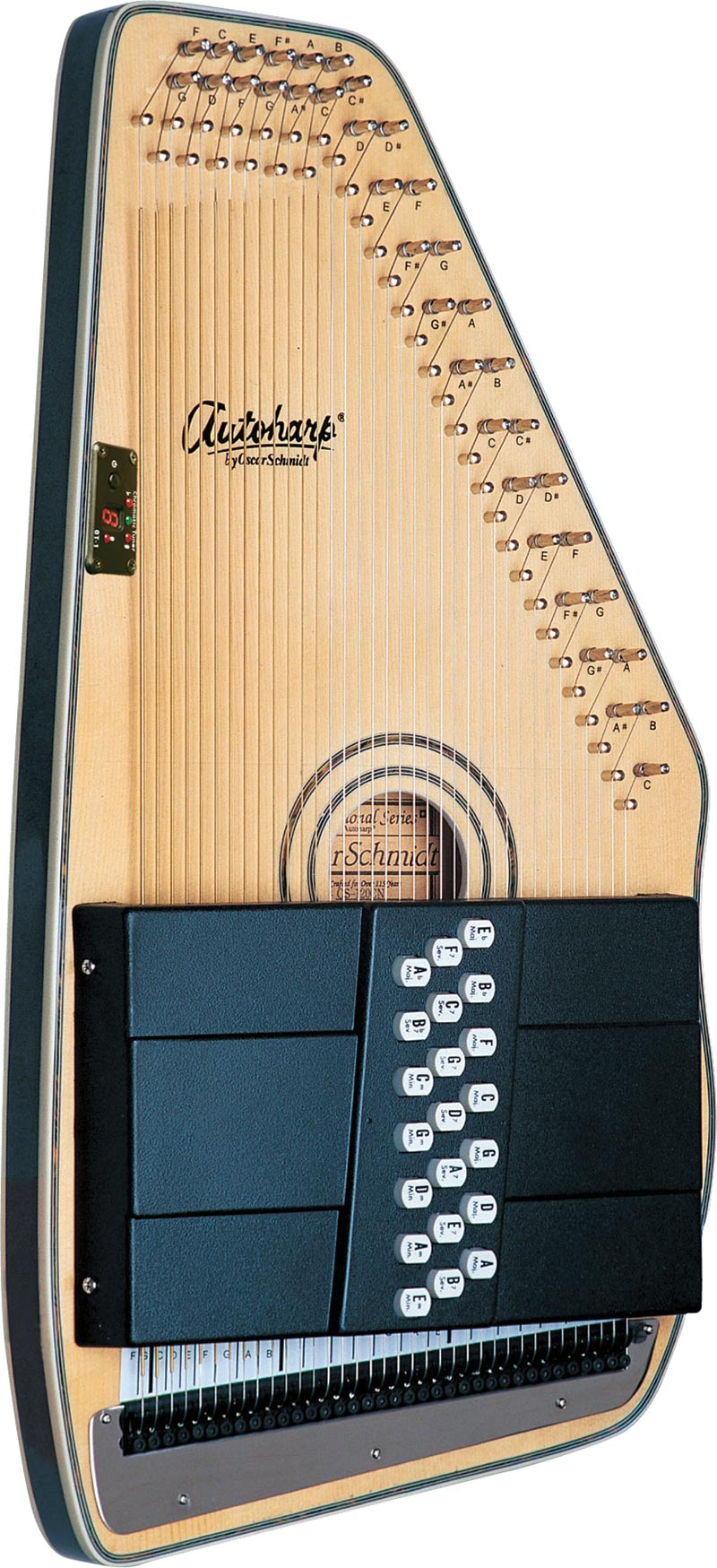
FIGURE 1. A modern autoharp with the Oscar Schmidt “Americana” tuning (photo by Alexandre Zindel; see Resources). The keyframe stretches across the strings, and pressing a button dampens some of the strings while leaving all strings for the indicated chord free to vibrate.
A zither has many strings stretched parallel to the plane of a flat soundboard and is played by plucking the strings. By comparison, harps are also played by plucking. However, by definition, they must have strings running in a plane vertical to the plane of the soundboard.
Zithers are very ancient instruments that are found all over the world. This is hardly surprising because as soon as you stretch a string over a resonant box, you have a zither! There are many kinds of zithers and it’s speculated that a type of zither tablature (which is musical notation showing the fingering for an instrument rather than notes) may well have led to the development of the five-line musical staff we use today.
Because they are quite easy things to make, America in the early 1900s experienced a sort of Cambrian Explosion of zithers, with a whole range of unusual “gizmo zithers” being produced by the Marxochime Colony of New Troy, MI, amongst others. These had various additions such as keyboards and different strumming and chord selection mechanisms.
The best known and perhaps most credible example of these is the Marxophone, which is still used today by several pop stars. If you search on your favorite online auction site, you can often find these on sale for several hundred dollars. I’ve often thought that some of these somewhat obscure “gizmo zithers” might make fun MIDI instruments.
The autoharp is a particular type of zither that was (arguably) invented by Charles F. Zimmermann in 1882 in America. The construction of the autoharp is such that it has many strings (typically 36 or more) that you usually strum, and a key-frame marked with chords that runs horizontally across the strings. When you press down the key for a particular chord, a bar pushes dampers onto some of the strings thereby silencing them. The remaining strings are open and free to vibrate and form the chord.
It’s really quite an exceptional instrument in that it’s the only “subtractive” acoustic instrument that I know of. You form a chord by subtracting strings from the vibrating set rather than by adding them. The autoharp is very easy to play (but still difficult to play really well) because there are no complex fingerings for chords. You press a button and the appropriate strings are damped to leave you with the chord you want.
Autoharps are flexible accompaniment instruments that can be used in a wide variety of different styles of music, and they are very popular today in the folk and popular music scenes. In fact, you can use an autoharp to provide a chordal accompaniment for more or less any style of music. While used mostly for chords, they are not limited to this because the more virtuosic players have worked out how to play them as melody instruments by plucking the strings like a harp.
I often wonder what the easiest instrument for a complete beginner to learn to play is, and the autoharp is always right up there at the top of the list. It’s also a uniquely joyful instrument because there is something inherently satisfying about getting large, rich, chords just by pressing a button and strumming a few strings!
As we’ll see shortly, the MIDI autoharp expands on the functionality of the acoustic autoharp by adding the almost infinite flexibility provided by MIDI output. However, like the MIDI lyre, it tries to keep itself as true as possible to the performance characteristics of the acoustic instrument on which it is based. The MIDI autoharp generates truly massive three and four octave chords making it a bit of an accompaniment powerhouse. It also has a “Lyre mode” that turns it into an enhanced transposing MIDI lyre, so you can play melody if you want.
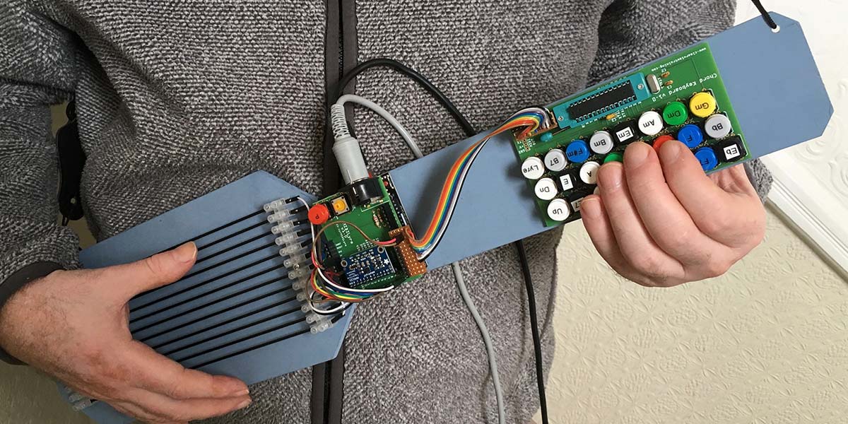
You can see a completed instrument in Figure 2. I have built this one in a ukulele or guitar form factor because I find that shape most comfortable to play. The chord keyboard is on the neck of the instrument; the Arduino/MIDI lyre shield is just above the body; and the 12 strings stretch across the body.
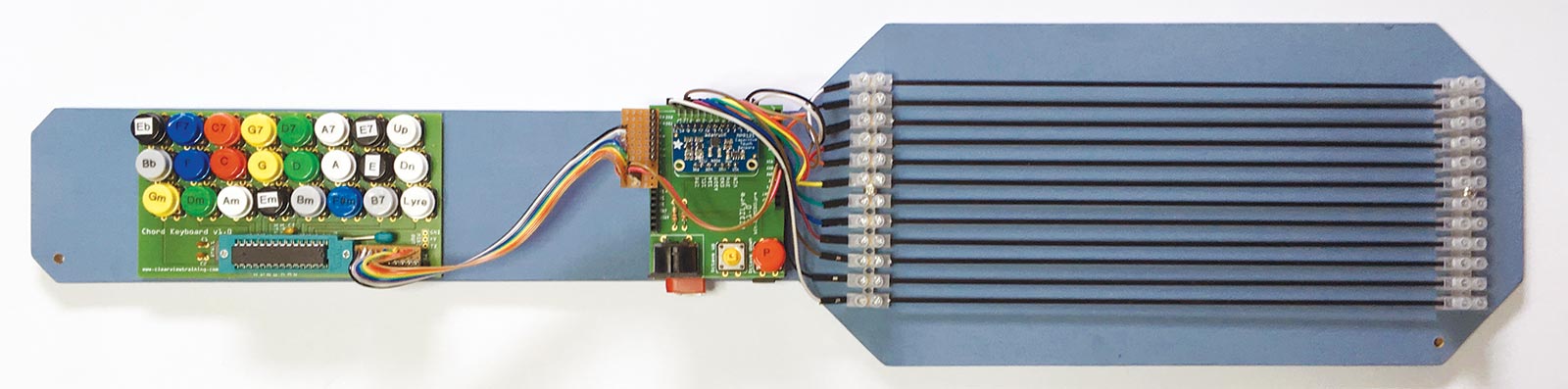
FIGURE 2. The completed MIDI autoharp in a ukulele form factor.
I’ll discuss mechanical construction of the autoharp in more detail towards the end of this article, but for now, it’s good to get an idea of what it looks like.
If you want a MIDI controller that is easy and fun to play and that makes a great accompanying instrument for just about any style of music, the MIDI autoharp is for you!
The Arduino Platform and Fritzing
I created this project on the Arduino platform to make it easy for anyone to build. If you aren’t familiar with Arduino, you’ll need to at least be able to download Arduino programs (called sketches) to the Arduino Uno board. I won’t go into details of this here because you can find complete instructions online at https://www.arduino.cc.
If you’re new to the platform, I suggest you start with “What is Arduino?” on that page, and then set yourself up with an Arduino development environment at https://create.arduino.cc.
Tip: Always start by downloading the Blink example program to your Arduino board to check that your development environment works!
The second piece of software you’ll need is Fritzing (http://fritzing.org/home). This is an amazing piece of free software that makes the process of creating electronic projects from breadboard through schematic to PCB accessible to the amateur. I created many of the diagrams in this article in Fritzing, and I also used it to create the PCBs.
You’ll find the PCB layouts in the Fritzing files (MIDILyrePCB005.fzz and ChordKeyboard019.fzz) with the article downloads. You can order PCBs directly from within Fritzing from Aisler (https://aisler.net), who I have found to be efficient, friendly, and reliable. I used Aisler myself, and for your convenience, the PCBs are already staged (https://aisler.net/p/BIBJNFMV, https://aisler.net/p/EXUZOKSL). Once you’re set up with Arduino and Fritzing, you are ready to go!
Designing the MIDI Autoharp
To create the MIDI autoharp, we need three things:
- A set of strings to strum.
- A set of chord buttons to select chords.
- MIDI output.
The first and third requirements have already been met with the MIDI lyre, and we’ll extend this instrument to meet the second requirement by adding a chord keyboard. We’ll see how to do this shortly.
This autoharp works somewhat differently to the acoustic version. As we mentioned above, in the acoustic autoharp, strings are damped and thereby subtracted from the vibrating set. We don’t need to do this in the MIDI version. Instead, when a chord button is pressed, we will dynamically retune all the strings to create precisely the chord we want. This means that we can get chords with a full three or four octave range with only 12 strings.
This is a very elegant solution because all 12 strings can be used all the time. We’ll discuss options for the MIDI lyre component next, and then move on to the chord keyboard.
The MIDI Lyre Revisited
The MIDI lyre was originally described in the July-August 2018 issue as a simple project that you could construct on a breadboard. Since then, I’ve designed an Uno shield that holds the lyre electronics more securely. This is shown in Figure 3 (and Figure 2). The shield makes the MIDI lyre very easy to construct and makes it a lot more robust than the breadboard version. Therefore, I recommend you use the shield for the MIDI autoharp project.
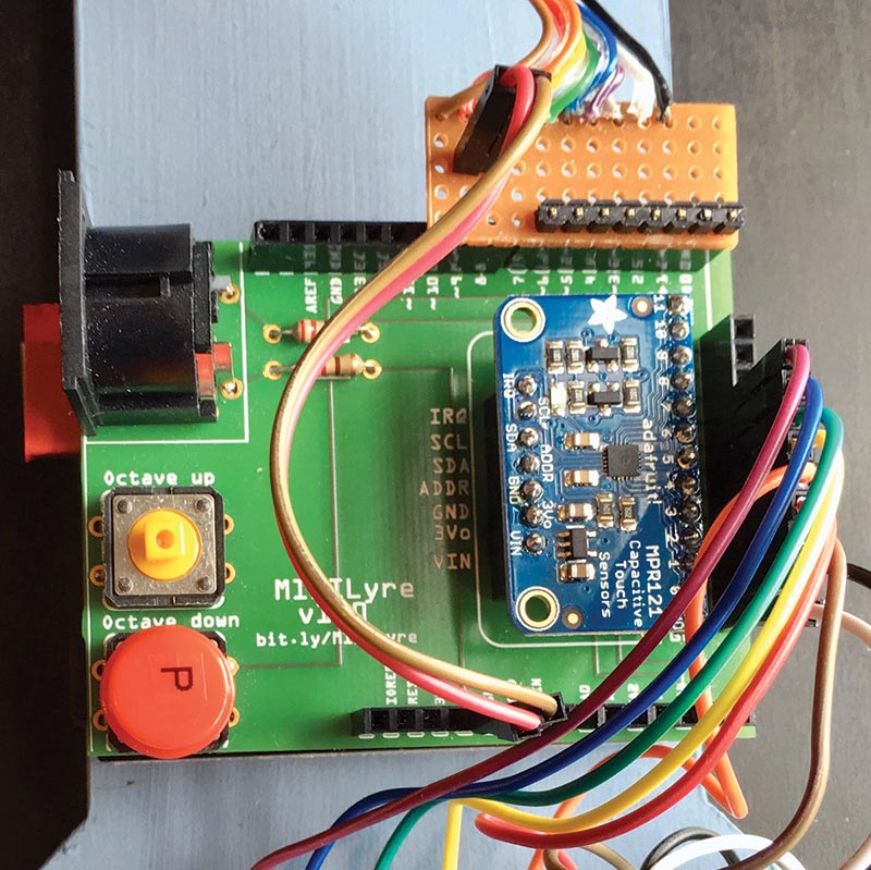
FIGURE 3. The MIDI lyre shield makes it simple to construct a MIDI lyre.
However, if you want to stick with the breadboard version, that will work just fine. You’ll just need to take 5V power for the breadboard from the Uno stripboard header (see later). You must also ensure that you have installed (at least) the octave down tactile switch because we’ll need it.
The MIDI lyre shield schematic is shown in Figure 4. You’ll find both the schematic and the PCB design in the Fritzing file MIDILyrePCB005.fzz. Note that the circuit is exactly the same as the original lyre.
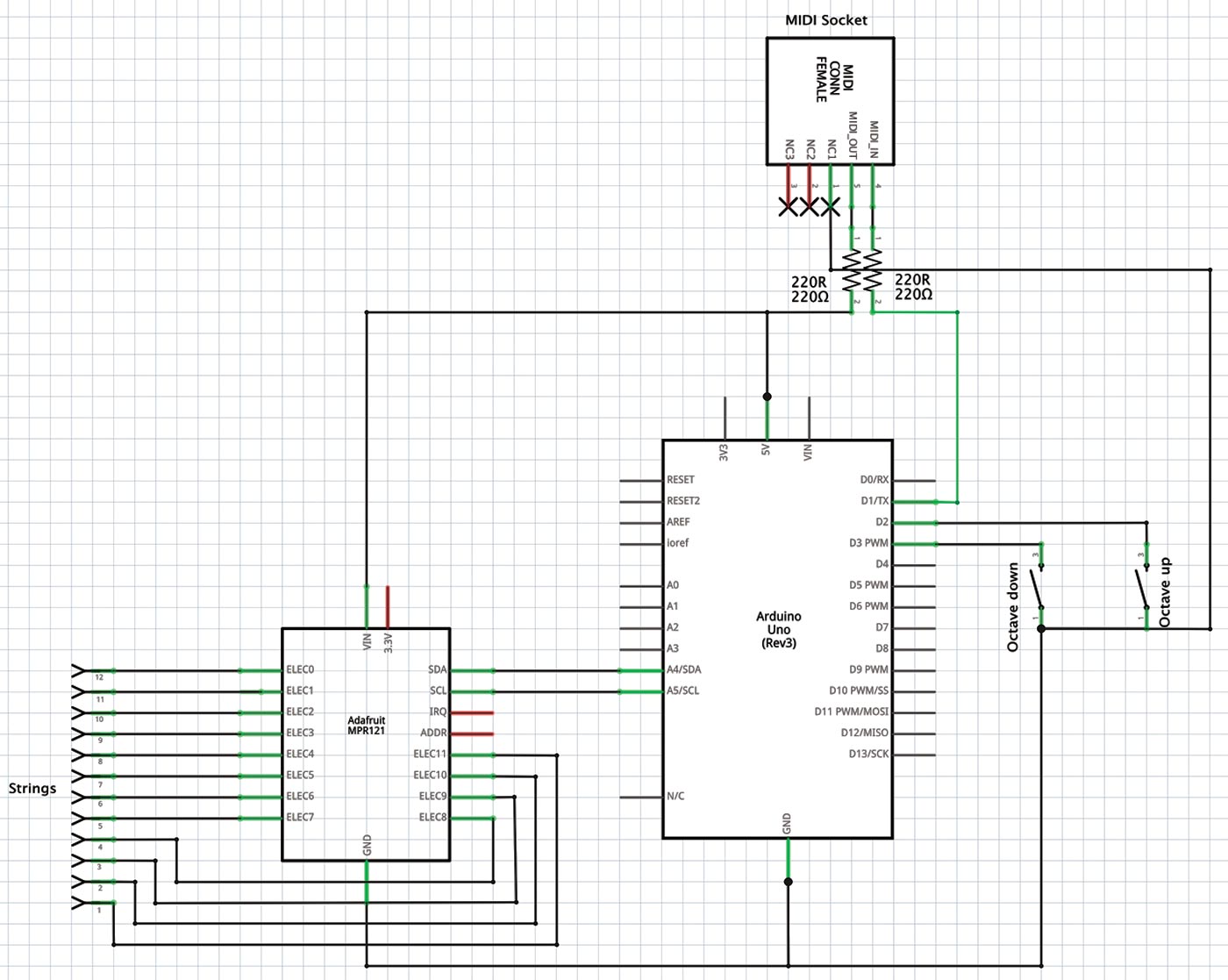
FIGURE 4. MIDI lyre shield schematic.
I suggest that you assemble the shield in the following sequence: Start by preparing the MPR121 breakout board. This comes with some headers that you need to solder in place. There are full instructions on the Adafruit site at https://learn.adafruit.com/adafruit-mpr121-12-key-capacitive-touch-sensor-breakout-tutorial/overview.
Next, solder all the headers onto the MIDI lyre shield. There are two types of header: the shield stacking headers with very long pins; and normal female headers for the MPR121 board and the string inputs. I suggest you begin with the shield stacking headers because these are the most critical.
Soldering these headers can be a bit tricky because you need to ensure they are correctly aligned to plug into the Uno. There is always just enough slack in the holes in the PCB to make this a challenge! The easiest way I have found to do it is as follows:
- Offer the lyre shield up to the Uno and insert the stacking headers so that the two boards are held together by the headers (see Figure 5).
- Flip the sandwich over so that the bottom surface of the Uno is facing upwards. Place it on a flat surface so that gravity holds the shield down against the bottom of the stacking headers.
- Gently ease the Uno away from the shield so that you expose a few more mm of the long header pins.
- Tack each header in place by soldering its first and last pins to the shield.
- Remove the Uno and solder the rest of the pins.
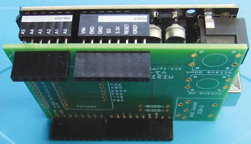
FIGURE 5. Aligning the stacking headers with the female headers on the Arduino Uno prior to soldering.
This procedure guarantees that the stacking header pins are accurately lined up with the Uno female sockets. Once the stacking headers are soldered, check by plugging it into your Uno. You’ll find that it’s a tight fit and that there is probably some interference with the Uno USB and power sockets because these extend above the top of the Uno female headers.
At this point, cover the top of the Uno USB port with a piece of masking tape to prevent any possibility of it shorting out the MIDI socket. THIS IS VERY IMPORTANT! Do it even if there is no interference because it’s better to be safe than sorry. It’s a “feature” of the Uno design that this port can easily short out shields because it raises above the board headers.
The shield headers for the MPR121 board comprise a seven-way and 12-way female header. If you can’t easily find a seven-way female header (I couldn’t), take an eight-way female header and snip off the last pin as close to the plastic as you can to make it seven-way. You can leave the final unconnected socket in place; it won’t do any harm.
Solder the seven-way header into the row of seven pads in the MPR121 footprint on the shield. Next, take a 12-way header and solder this into pads 0 to 11 of the row of 13 pads (0 to 11 plus GND) in the MPR121 footprint. Do not solder to the GND pad because it’s never used.
At this point, check how the MRP121 breakout board fits in the headers. Solder the 12-way female string input header. If you like, you can omit this header and solder the wires for the strings directly. I prefer to use a header so that I can use the board with different sets of strings.
To complete the board, solder in place the two 220R resistors, the two tactile switches, and the MIDI socket. The shield is a tight fit against the Uno USB and power ports, so you’ll need to trim the pins of the MIDI socket as far back to the board as you can.
To install the shield on the Uno, push it firmly into place making sure all the long stacking header pins are well seated. You typically won’t get the full length of the pins all the way into the Uno headers, but so long as you push everything firmly together, it will be fine. Double-check that the Uno USB port is protected by masking tape (as I mentioned earlier) and that there are no shorts to the underside of the MIDI socket. The completed MIDI lyre shield is shown installed in the MIDI autoharp back in Figure 3.
As I said above, this shield is a direct replacement for the original breadboarded MIDI lyre, and will work just fine with the original MIDI lyre software. However, for the MIDI autoharp, we’ll need different software that I will describe shortly.
The Chord Keyboard
The lyre shield takes care of the strings and MIDI output. So next, we need to consider a way to select the chords. We’ll create a chord keyboard comprised of 24 tactile switches arranged in a typical autoharp pattern.
There are many possible autoharp chord keyboard layouts with different numbers or arrangements of keys. We’ll use the layout for a 21-chord autoharp shown in Figure 6. This is the popular Oscar Schmidt “Americana” layout that is particularly useful for pop, folk, and Bluegrass music because it has E major, F# minor, and B minor chords. Of course, you can tune the MIDI autoharp however you like, but it’s sensible to stick to a standard tuning and key layout for compatibility with acoustic instruments.
For convenience, the tonics in Figure 6 are color-coded. I was fortunate enough to find a set of tactile switches that had seven different colored key caps (as shown in the figure), so I could color each of the seven tonics (C, D, E, F, G, A, B) differently. Therefore, all C chords (C major, C7, and C minor) are red, all G chords (G major, G7, and G minor) are yellow, and so on.
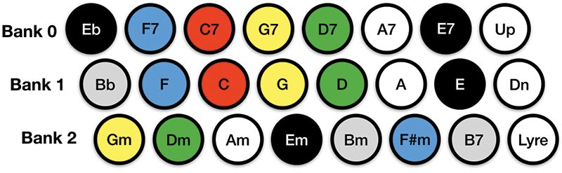
FIGURE 6. Key layout for the MIDI autoharp.
If you want to make music very easy to play, take a piece of music that has the chords already marked and color each chord according to the chord keyboard. Note that I had to use white because the keycap colors for the tactile switches I used is very limited. You can use an underline or circle for marking the white chords. The non-chord Up, Dn, and Lyre keys can be any color you like. It’s worth taking the time to understand the chord layout of the chord keyboard. Consider Table 1/Bank 1, which is the middle row. This row contains the major chords, and the layout is based on a circle of fifths which means there is a fifth between the tonics of adjacent chords
| Column |
0 |
1 |
2 |
3 |
4 |
5 |
6 |
7 |
| Bank 0 |
Eb
Eb G Bb
0 |
F7
F A C Eb
1 |
C7
C E G Bb
2 |
G7
G B D F
3 |
D7
D F# A C
4 |
A7
A C# E G
5 |
E7
E G# B D
6 |
Up
7 |
| Bank 1 |
Bb
Bb D F
8 |
F
F A C
9 |
C
C E G
10 |
G
G B D
11 |
D
D F# A
12 |
A
A C# E
13 |
E
E G# B
14 |
Dn
15 |
| Bank 2 |
Gm
G Bb D
16 |
Dm
D F A
17 |
Am
A C E
18 |
Em
E G B
19 |
Bm
B D F#
20 |
F#m
F# A C#
21 |
B7
B D# F# A
22 |
Lyre
6 |
TABLE 1. This table shows the three banks of chords. For each chord (top to bottom), we have the chord’s name, the three or four note chord, and the switch number. If you decide to retune the MIDI autoharp to your own specifications, you should begin by making a similar table.
For example, we start at the left with Bb major (Bb D F), the next chord begins on the fifth of this chord (F) and is F major (F A C); the next chord begins on the fifth of this and is C major (C E G), and so on for the rest of the row.
Bank 2 (bottom row) contains the minor chords and is also based on the circle of fifths up to and including F#m. We then have a useful B7 chord thrown in breaking the pattern. This is purely a matter of pragmatics because B7 is musically more useful than the expected C# minor.
Bank 0 starts with the equally useful Eb major (rather than the more obscure Bb7) and then has seventh chords starting on F7 that are again based on the circle of fifths.
The rationale for this layout is that most popular music only uses three chords, and these chords are usually a fifth apart. For example, D major is the most popular key for folk music, and most songs in this key use D major, G major, and A major (or seventh) chords. These are situated right next to each other on the keyboard. In fact, the layout arranges the 21 chords for maximum convenience.
Given that the chords for the vast majority of three chord tunes are close together on the keyboard, you can prepare to play a tune by placing one finger on each of the three chords. Then, all you need to do is press the right finger down at the right time and strum. Even better, with the MIDI autoharp, you can release the key once you have pressed it and the instrument will hold the tuning for that chord until the next chord key is pressed.
The instrument ignores successive presses of the same chord key. The action of each chord key is to retune the whole instrument (more or less) instantaneously to the selected chord.
At the end of each bank are “user” keys that I have assigned for octave up, octave down, and Lyre mode. Unlike the chord keys, the octave keys don’t latch but have a rather generous 0.5 second debounce time. This means that you can press the same octave key repeatedly and the octave will increment or decrement.
Lyre mode toggles the autoharp strings from a chord pattern to a diatonic pattern in Mixolydian mode as originally described in the MIDI lyre article. All that Mixolydian mode means is that the scale starts three notes below the tonic. So, if the last chord button pressed was C, the tonic is C, and the scale for the 12 strings is C major (starting on G), G A B C D E F G A B C D.
If the last chord button pressed was D, the tonic is D, and the scale is D major (starting on B), B C# D E F# G A B C# D E F#. It’s important for the scale to start at least three notes lower than the tonic because many tunes have a “lead in” that starts one, two, or three notes below the tonic.
Notice that Lyre mode turns the autoharp into a melody instrument where the strings can be tuned to one of the scales F, C, G, D, A, E, Bb, and Eb (= F#). The Bb and Eb tunings are particularly useful for playing with transposing instruments such as clarinets, saxophones, and trumpets.
In Table 1, we see that we have 21 different chords in total, but there are only three types of chord: the major; the minor; and the seventh. We can express the notes in these chords as numbers of semitones above a tonic as shown in Table 2. This creates a chord pattern that describes the structure of each type of chord relative to an arbitrary tonic.
| Chord type |
Major |
Minor |
Seventh |
| Semitones above tonic |
0, 4, 7 |
0, 3, 7 |
0, 4, 7, 10 |
| Example (tonic = C) |
C, E, G |
C, Eb, G |
C, E, G, Bb |
TABLE 2. The patterns of semitones above the tonic for each type of chord.
In the lyre project, we learned that MIDI represents each note as an integer in the range 0 to 127 where MIDI number 60 is (usually) middle C, and each semitone is one unit. Thus, given a starting tonic and a chord type, we can calculate the MIDI numbers for the notes in that chord just by applying the appropriate chord pattern. For example, the MIDI numbers for the notes in the C major chord starting on middle C would be:
60 + 0, 60 + 4, 60 + 7 = 60, 64, 67
Our MIDI autoharp has 12 strings. This means that for the three-note major and minor chords, we have enough strings to repeat the chord pattern four times, giving us massive four octave chords! For the four-note seventh chords, we can repeat the pattern three times giving us three octave chords. The appropriate numbers are shown in Table 3 where the brackets indicate octaves. Note that the corresponding notes in each octave always differ by 12 because there are 12 semitones to an octave.
| Chord type |
Chord pattern over 12 strings |
| Major four over octaves |
(0, 4, 7), (12, 16, 19), (24, 28, 31), (36, 40, 43) |
| Minor four over octaves |
(0, 3, 7), (12, 15, 19), (24, 27, 31), (36, 39, 43) |
| Seventh three over octaves |
(0, 4, 7, 10), (12, 16, 19, 22), (24, 28, 31, 34) |
TABLE 3. The pattern of semitones for three and four octave major, minor, and seventh chords. The brackets indicate octaves.
To calculate the MIDI numbers for a specific four or three octave chord, we just have to add the MIDI number for the tonic of that chord to each value in Table 3. In this way, we can tune the MIDI autoharp for any chord we like.
The Chord Keyboard Electronics
The schematic for the chord keyboard is shown in Figure 7. You’ll find this schematic and the PCB design in the Fritzing file ChordKeyboard019.fzz. Although there are a lot of wires on the schematic, the design is actually very simple.
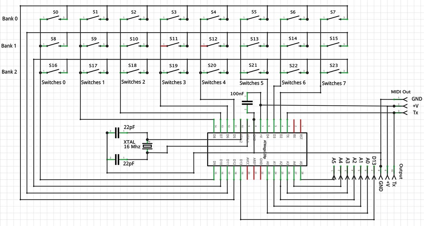
FIGURE 7. Schematic for the MIDI autoharp chord keyboard. We’re using a specially programmed ATmega328p chip to act as a bespoke keyboard encoder for the 24 keys. The MIDI Out header is for future projects.
There is a 3x8 matrix of tactile switches that is scanned by a specially programmed ATmega328p, which is the chip used in the Uno. The crystal and two capacitors provide a clock for the chip.
Because of the large number of switches, the best way to construct this is on a PCB unless you like lots of point-to-point wiring. The chord keyboard is what we might call a “smart peripheral” because it contains its own specially programmed ATmega328p microcontroller. In fact, this makes it a very flexible component, and we will see in a follow-on article that it can be easily turned into a stand-alone MIDI instrument.
The ATmega328p scans the 3x8 matrix of 24 tactile switches and outputs a binary number corresponding to the key number for each key as shown in Table 1. Matrix encoding is the best way to handle a lot of switches because for an n by m matrix, you only need to use n + m microcontroller pins rather than the n x m pins you would need if each switch was individually connected.
Back in the late 1970s, there was a great little chip called the 74922 that was a 16-key encoder chip (a 4 x 4 matrix). A couple of these would have done very nicely for the MIDI autoharp. Sadly, these chips are now obsolete, although they are so useful you can still get old stock or clones.
If you’re interested in matrix keyboards, it’s well worth taking the time to look at the 74922 datasheet because it explains how to do key encoding very clearly (http://ee-classes.usc.edu/ee459/library/datasheets/MM74C922.pdf).
We’ll make our own keyboard encoder for the chord keyboard using a specially programmed ATmega328p. It’s very easy to program these chips using an Arduino Uno board, and you can then run them stand-alone by adding a 5V power supply, a 16 MHz crystal, and a couple of 22 pF capacitors. If ever you need bespoke chips for your own projects, you should consider this approach because it’s very easy.
To program the chip, you’ll need the following:
- The MIDI autoharp chord keyboard encoder sketch chord_keyboard_scanner001.ino.
- An ATmega328p chip with bootloader.
- An Arduino Uno.
You can buy ATmega328p chips from the usual sources (I recommend Adafruit or SparkFun), but you must make sure that you buy a chip that has the Arduino bootloader installed! This is essential because the ATmega328p needs the bootloader to function in an Arduino board, and we’ll be using an Arduino board as a simple programmer.
When a chip with a bootloader is placed in an Uno, the bootloader runs and enables sketches to be downloaded in the usual way via the USB port. Chips without bootloaders simply won’t work!
You’ll find lots of ATmega328p chips with bootloaders advertised on Amazon or eBay from a range of sellers, but my experience with this is that you tend to get what you pay for, and, if the chip seems very cheap, there may be problems.
It’s worth mentioning in passing that you can buy “raw” ATmega328p chips and install the bootloader yourself. This is not difficult, but is beyond the scope of this article. Go to https://www.arduino.cc/en/Tutorial/ArduinoToBreadboard for details.
Program the chip as follows:
- With the power off, carefully remove the existing ATmega328p chip from an Arduino Uno board. I recommend using a chip puller for this (it’s a very worthwhile investment!), but you can use a small screwdriver to carefully ease the chip out of the socket, working slowly from each end in turn. Be careful not to bend the pins.
- Insert your new ATmega328p (with bootloader!) into the empty socket. If the pins are a bit splayed out, you may need to bend them in a little first. You can use a pin straightening tool (sometimes known as an “IC straightener” — another great investment), or just place the chip on its side on a flat conductive surface and gently rock the chip back and forth to bend the pins inward a bit.
- Program the chip with the chord keyboard sketch chord_keyboard_scanner001.ino in the usual way.
- With the power off, carefully remove the programmed chip, and re-insert the original chip to get your Arduino back in operation just as it was before.
The chips are static sensitive, so be sure to take all the usual precautions such as working on an anti-static mat, and grounding yourself before touching the pins. Also, make sure every one of the pins is seated correctly in the socket and not bent under the chip.
Congratulations! You have now made your own bespoke keyboard encoder chip for the chord keyboard!
The Chord Keyboard Encoder Software
If you look at the keyboard encoder software (chord_keyboard_scanner001.ino), you’ll see that it is quite generic. It organizes the keyboard into NUM_BANKS banks of NUM_SWITCHES switches; for the MIDI autoharp, there are three banks of eight switches. Switches 0..6 in each bank are for chords (see Table 1), and switch 7 in each bank is a “user” switch that behaves somewhat differently as we will soon see. When a key is pressed, the keyboard encoder returns a five-bit binary number on pins A0 to A4 calculated as follows:
b is the bank number, s is the switch number in the bank, and there are NUM_SWITCHES switches per bank.
Therefore:
SwitchNumber = (NUM_SWITCHES * b) + s
For the MIDI autoharp chord keyboard NUM_SWITCHES = 8, 0 <= b <= 2, and 0 <= s <= 7, so:
SwitchNumber = 8*b + s
The first switch (bank 0, switch 0) is numbered 0 and corresponds to the Eb major chord; the last switch (bank 2, switch 7) is numbered 23 and is Lyre (for Lyre mode). You should be able to see from the code how the keys are scanned. Each bank, b, is made low in turn, and each switch number in the bank, s, is read. So, we don’t have to use any pull-up resistors. The pins that read the seven switches in each bank (pins 9, 8, 7, 6, 5, 4, 3, 2) are defined INPUT_PULLUP and each bank pin (D10 = Bank 2, D11 = Bank 1, and D12 = Bank 0) is active low.
In other words, when one of the seven switch pins goes low, this means that the button for that switch in the currently active low bank has been pressed. The result of a keypress is that the keyboard encoder outputs the appropriate binary number on pins A0...A4 and pulses A5 to indicate the change. A positive edge on A5 indicates that there is a valid binary number on A0...A4.
For the chord keys (i.e., all keys except the “user” keys 7, 13, and 23), the output latches. This means that pins A0...A4 hold the value of the key until a different key is pressed. This has a couple of advantages.
Firstly, it makes the keyboard very ergonomic because you don’t have to hold a key down; you only have to press it once to select a chord. Secondly, it means we don’t have to worry about debouncing the switches. When a key is pressed, that value is latched until a different key is pressed, so switch bounce has no effect.
The three “user” keys work somewhat differently to the chord keys. The user keys are debounced and behave (more or less) like normal non-latching keys on a computer keyboard. This is necessary because we may need to press the same user key several times to increment or decrement the octave, or to toggle Lyre mode.
Assembling the Chord Keyboard PCB
Construction of the chord keyboard PCB is very simple. Begin by soldering the 24 tactile switches. If the switches have key caps, I suggest you remove these prior to soldering so that you can ensure that each switch is seated all the way down on the PCB. Next, solder the 28-pin DIP socket for the ATmega328p and the 10-way female header. After that, you can add the 16 MHz crystal, the two 22 pF capacitors, and the 100 nF decoupling capacitor.
Finally, insert the ATmega328p you programmed as a keyboard encoder chip. Be sure to insert it the right way; the notch on the chip points away from the crystal and towards the 10-way female header.
The completed chord keyboard is shown in Figure 8. Notice that I have used a slimline 28-pin ZIF (Zero Insertion Force) socket to make the chip easily removable for reprogramming. You don’t need to do this, but I found it to be very useful when I was developing the code and had to reprogram the chip a lot.
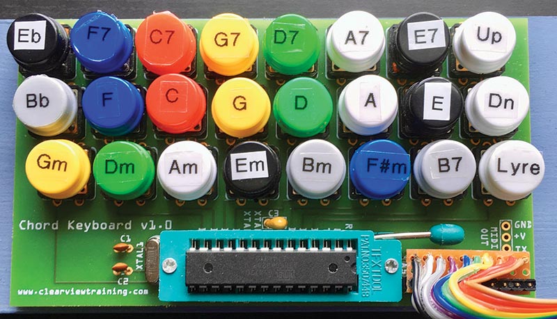
FIGURE 8. The completed chord keyboard PCB. You don’t need to use a Zero Insertion Force (ZIF) socket for the ATmega328p unless you want to make a lot of software changes. I used a labelling machine with clear and white tapes to label the switches according to Figure 6.
When a tactile switch is pressed, a binary number is output on the header pins as shown in Table 4. If you power the board up with 5V, you should find the binary number 01010 = 10 (decimal) on the output. This is the default chord, C major, which corresponds to Bank 1, Key 2 (see Table 1).
| Header Pin |
A4 |
A3 |
A2 |
A1 |
A0 |
| Bit |
24 |
23 |
22 |
21 |
20 |
TABLE 4. The chord keyboard outputs a binary key number on header pins A4...A0. Pin A5 is used as a positive edge clock to indicate a valid output is present.
Each time a tactile switch is pressed, the output number changes according to Table 1, and the board outputs a positive edge on A5. You can check for this edge if you have an oscilloscope or a logic probe that detects pulses.
We use this positive edge to trigger an interrupt on the MIDI lyre shield to tell it to read the chord keyboard. Remember that the chord keyboard is latching, so once you press a key, the keyboard output holds that number even when the key is released.
The MIDI Autoharp Software
The MIDI autoharp software is in the Arduino sketch midi_autoharp_001.ino that you can get from the article downloads. You should load this into the Uno that has the lyre shield attached in the usual way. This software is a version of the original MIDI lyre software that has been extended to work with the chord keyboard. If you look at midi_autoharp_001.ino, the new software should be reasonably clear, especially if you are already familiar with the MIDI lyre software.
The loop( ) function — which is the standard Arduino main loop — calls the negativeEdge( ) function, which works out what strings have just been released and sends the appropriate MIDI note on messages to the synthesizer via the MIDI socket. This is exactly what the original MIDI lyre software does. The loop is kept very tight with minimal code, so that the latency (the time between “plucking” a string and the synthesizer sounding) is as small as possible. In fact, it is not perceptible.
The big difference between the MIDI lyre and the autoharp software is in the way interrupts are handled. In the original MIDI lyre, interrupts on pins 2 and 3 were connected to the Octave Down and Octave Up buttons, respectively. In the MIDI autoharp, we connect the interrupt on pin 2 (Octave Down button) to the A5 pin of the chord keyboard. When there is a positive edge on this interrupt, the function interruptHandler( ) is called. This is where all the interesting MIDI autoharp stuff happens! This means that when the lyre shield is used with the chord keyboard, this button doesn’t actually do anything, so you can leave the key cap off. The interrupt on pin 3 (Octave Up button) is connected to the panicInterruptHandler( ) function that sends a note off to all 127 MIDI notes. This “MIDI panic” lets you stop all notes that are playing.
You should label the Octave Up button on the lyre shield “P” for “Panic”! A MIDI panic button is always useful on a MIDI controller! It’s especially helpful on the MIDI autoharp because it doesn’t send MIDI Note Off events. So, if you select a voice with sustain, the voice will continue to play rather than die away. We’ll consider choice of voices more carefully later.
When a chord key is pressed, the interruptHandler( ) function works as follows:
- Read the binary number from the chord keyboard and convert this to the integer CurrentKey.
- Find the tonic for the key which is Tonics[CurrentKey].
- Find the 12-number chord pattern array for the key which is Chords[CurrentKey].
- Retune the strings by calculating the new MIDI number for each string according to the following pseudo code:
For j in 0..11<br />
  Strings[ j ] = Tonics[CurrentKey] + Chords<br />
  [CurrentKey] [ j ] + octave * 12
The array Strings[ ] contains the current tuning as a MIDI number for each of the 12 strings. The octave variable is an integer 0 <= octave <= 6. To convert this to a MIDI number, we must multiply it by 12 because there are 12 semitones in an octave. This is added to each note to transpose it into the right octave.
If the key pressed corresponds to user key 0 (U0 in the code), the interruptHandler( ) function increments the octave variable keeping it in range, and recalculates the string tuning in Strings[ ] as above. Similarly, if the key is U1, octave is decremented keeping it in range, and the string tuning is recalculated.
If the key number is U2, this puts the MIDI autoharp into Lyre mode. In this mode, the tuning for the strings is calculated exactly as above, but we now use the chord pattern in the array LyreTuning[ ] rather than Chords[CurrentKey].
This chord pattern tunes the strings in a diatonic scale in Mixolydian mode on the current tonic (Tonics[CurrentKey]) in the current octave. Notice that Lyre mode picks up the last tonic and octave that was set. So, for example, to play in Eb, you would press the Eb key, select the octave you want, and then press Lyre. We already described Lyre mode in a bit more detail in the “The Chord Keyboard” section above.
You can change some constants in the code if you want to customize the tuning of the MIDI autoharp. The constant arrays Maj[ ], Sev[ ], and Min[ ] contain the chord patterns for major, seventh, and minor chords, respectively. If you want other chords — say, diminished seventh chords — then you can make up your own chord pattern arrays for them.
The assignment of the chord patterns to the keys is done in the constant array Chords[ ]. The assignment of the tonics to the keys is done in the constant array Tonics[ ]. By modifying these two arrays, you can assign new tonics and chord patterns to each chord key.
I’ve kept the code as simple as possible with everything in its own array, to try to make it as transparent and easy to modify as I can. Also, there is quite a bit of debugging code. If you uncomment the line:
//#define DEBUG
at the top of the file, then MIDI will be disabled (!) and debugging information will be printed out on the serial port. You can see this information in the online Arduino development environment by selecting “Monitor” in the leftmost pane. This can help you out if you do any customizations. However, don’t forget to comment out the line again when you want to test your new code! Otherwise, you can spend quite a long time wondering why nothing is happening.
Connecting the Chord Keyboard to the MIDI Lyre Shield
The chord keyboard and MIDI lyre are linked by a 10-way ribbon cable with a stripboard adapter at both ends (Figure 9). I’ll assume that you are using the MIDI lyre shield, but if you’re using the breadboard version, you should plug the stripboard adapter directly into the Uno and take 5V power for the breadboard off the adapter as mentioned earlier.
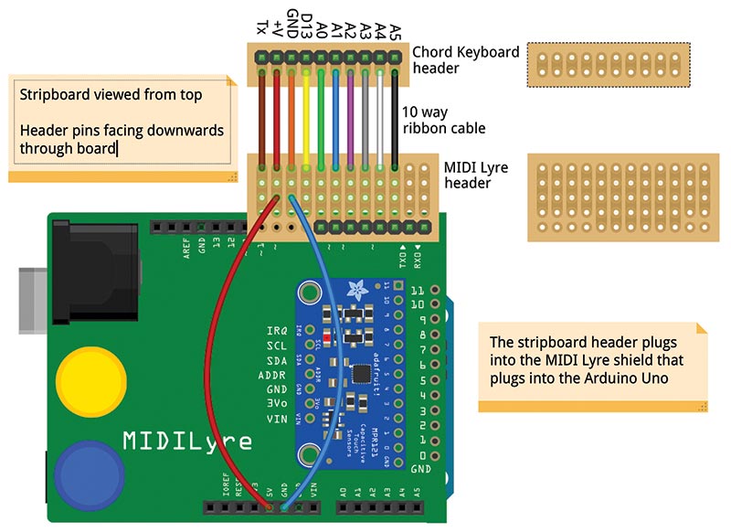
FIGURE 9. Ribbon cable and stripboard adapters plugged into the MIDI lyre shield. Note that the stripboard is shown from above (the non-copper side). The red and blue wires are Dupont male/male leads soldered directly into the MIDI lyre header. The ribbon cable is not shown to length and should be about 15 cm.
I suggest you start by preparing the male headers for both pieces of stripboard. The male header pins need to protrude through to the back of the board and extend enough so that they can be plugged into the MIDI lyre shield and chord keyboard female headers.
Unless you can buy male headers with extra long pins, you’ll need to modify them slightly so that the pins protrude more than normal.
There is a trick to doing this. Hold the header upright on a flat surface so that it stands on its shorter row of pins and place the appropriate piece of stripboard on top of it. Gently press the stripboard down until the plastic part of the header touches the surface and you can push no farther. I find it’s best to press one end down a bit, then press the other end down in a sort of rocking motion. Work gradually until you get the hang of it, then it will go very quickly. You should now have a header with long pins on one side only.
You can insert this from the top face of the stripboard, and even after soldering the copper side, there will be plenty of pin left to make a secure connection with the Uno and chord keyboard. Obviously, try to solder neatly without smearing solder up the length of the pins.
Next, prepare two pieces of stripboard as shown in Figure 9. Note the positions of the track breaks and carefully cut the tracks. Solder the male and female headers remembering that the male header pins point down through the board.
Solder the 10-way ribbon cable between the two pieces of stripboard as shown. Finally, check your work with a multimeter as follows:
- Check for shorts between adjacent tracks.
- Check the ribbon cable assembly for continuity according to Table 5.
| MIDI Lyre Shield |
Chord Keyboard Header |
| Rx |
N/C |
| Tx |
N/C |
| 2 |
A5 |
| 3 |
A4 |
| 4 |
A3 |
| 5 |
A2 |
| 6 |
A1 |
| 7 |
A0 |
| N/C |
D13 |
| GND |
GND |
| 5V |
+V |
| N/C |
Tx |
TABLE 5. Connections between the MIDI lyre shield and the chord keyboard.
Stringing the MIDI Autoharp
The MIDI autoharp is strung exactly the same way as the MIDI lyre, so if you have made the lyre, you’ll know all the tricks. There are 12 “strings” made of 200 mm lengths of 3 mm diameter extruded carbon fiber rod. This is readily (and cheaply) available online or from hobby shops and is usually sold by the meter. It’s stiff enough so that we don’t need to tension it, and conductive enough so that it makes a decent touch sensor.
Note that for the original MIDI lyre, we used 333 mm long strings because this is a good length for a small lyre, and we can get three strings to the meter. The MIDI autoharp is a strummed instrument rather than a melody instrument, so we can use shorter strings that are closer together.
I find that 200 mm strings give plenty of room for strumming, and you can get four of these from a one meter rod, so you only need three rods for a set of 12 strings. Take a look at Figure 10.
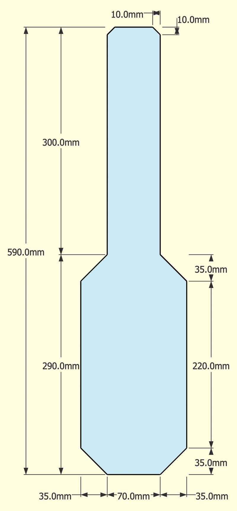
FIGURE 10. Plans for a ukulele form-factor MIDI autoharp cut out of 6 mm MDF sheet.
To prepare the strings, cut 12 pieces of carbon fiber rod 200 mm long. A good approach is to tape three one meter lengths of rod together at each end with masking tape. Tape and mark the three 200 mm sections and cut all the rods together with a hacksaw or bandsaw. Carbon fiber rod is surprisingly easy to cut.
Once you have the rods, you need to insert them into the barrier strip. For the MIDI lyre, we used two 12-way terminal barrier strips with a 12 mm spacing between terminals (this is usually the 15A rated model). This gives a comfortable string separation so that each note can be played individually.
However, as I have already said, the MIDI autoharp is (primarily) a strummed instrument, so for ease of strumming we should go for a narrower string separation of 8 mm. This is normally the 5A rated model. Ensure that you get a terminal barrier strip that has the brass tube screw terminals.
Other types of terminal may or may not accept the rods! As I described in the MIDI lyre article, there is a very particular way to string this instrument, unless you want a lot of frustration!
- Loosen all the screws in a barrier strip so that you can pass the rods right through it until the strip is about halfway along the rods.
- Take the second barrier strip and open one row of contacts and close the other.
- Pass each rod into the open contact of the second barrier strip until it stops against the closed contact and tighten the open contact to just hold the rod firmly.
- Slide the first strip down so that it’s flush with the ends of the rods and gently tighten both rows of screws.
Carbon fiber rod is quite easy to crush, so make sure you don’t tighten the nuts too much. You will now have a set of 12 strings stretched between the two barrier strips, and one of the strips will have a row of closed contacts that you can use to connect male-to-male DuPont connectors that will connect the strings to the MIDI lyre shield.
Assembling the MIDI Autoharp
You can see back in Figure 1 that the acoustic autoharp has unique ergonomics because the keyframe is stretched across the strings. It can be played when placed on a table, but if you look at performers on YouTube, you generally see them holding the instrument to their chests, and reaching around it to strum and press the keys. In fact, this is a reasonably comfortable playing position, although it does dampen the sound of the instrument slightly.
Arlow’s Law — based on almost 25 years of luthierie — states that “all plucked instruments aspire to the condition of the guitar.” This is because in many ways, the guitar has near optimal ergonomics, which is surely one of the reasons for its popularity. We will therefore construct the MIDI autoharp in a guitar-like or ukulele-like form factor.
However, if you want a more traditional “autoharp” looking instrument, feel free to do that, but remember that the strings are capacitive touch sensors, so there are important constraints. You don’t want to hold the strings too close to your body or have your left hand (chord keyboard) too close to your right (strings).
In particular, you should probably not have the chord keyboard running across the strings. This pretty much rules out a completely traditional autoharp form-factor!
My original MIDI autoharp was assembled on a base of 6 mm MDF cut into what is pretty much a tenor ukulele shape. The plans are given in Figure 11. I used small screws through the barrier strips to mount the strings, and blobs of hot melt glue to mount the chord keyboard and the Uno.
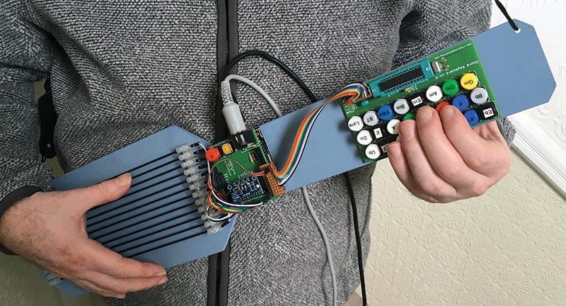
FIGURE 11. The author using a guitar strap with the MIDI autoharp.
Tip: Put the blobs of glue on the baseboard (not the PCBs) and then offer up the PCBs to the glue. Figure 10 shows me playing the MIDI autoharp, and you can see the ukulele form-factor gives a very comfortable playing position — especially when used with a guitar strap as illustrated.
Voices for the MIDI Autoharp
Both the MIDI autoharp and the MIDI lyre impose a constraint on what synthesizer voices you can use. The constraint is that the voice should not have any sustain. I rather skimmed over this in the MIDI lyre article, so I will go into a bit more detail here.
In a synthesizer, the envelope generator allows you to control how the amplitude of the note varies with time. All envelope generators have a minimum of two adjustable parameters (Attack and Decay), but usually they have at least four:
- Attack: Determines how quickly the amplitude of the note rises to its maximum value immediately after a MIDI Note On event. The amplitude is set to the maximum of 127 for the MIDI autoharp and lyre. With keyboards, the maximum amplitude usually depends on how hard you press a key.
- Decay: How quickly the note decays to its sustain level.
- Sustain: The amplitude the note maintains after the decay until a MIDI Note Off event.
- Release: How quickly the amplitude of the note decays to zero after a MIDI Note Off event.
This combination of Attack, Decay, Sustain, Release creates what is known as an ADSR envelope. You can see it graphed in Figure 12.
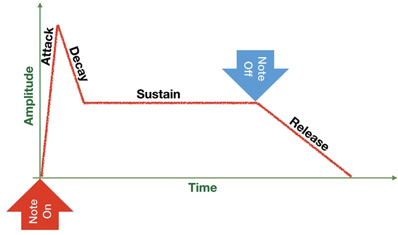
FIGURE 12. A simple ADSR envelope. There are more complex variants of this that have even more adjustable parameters. Envelopes with Sustain are not suitable for use with the MIDI autoharp and lyre.
Notice that sustain holds the volume until a MIDI Note Off event. The MIDI autoharp and lyre do not send MIDI Note Off events, so any voice that has a non-zero sustain is unsuitable because it will just keep sounding once it‘s activated. What we need are voices that have sustain set to zero as shown in Figure 13.
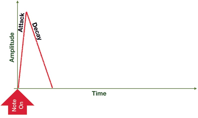
FIGURE 13. An Attack Decay envelope. Sustain is set to zero, so there is no wait for a MIDI Note Off event and therefore no Release. This sort of envelope is suitable for the MIDI autoharp and lyre.
This kind of envelope has no Sustain, and therefore no Release, and it does not wait for a MIDI Note Off event. As such, it behaves similarly to a plucked instrument — and this is exactly what we want. To make voices compatible with the MIDI autoharp and lyre, go into the envelope generator of your synth and set the sustain to 0.
Final Notes
I’ve noticed that a few software synths don’t process MIDI Note On events for notes that are already on. I’m not sure whether this is a valid interpretation of the MIDI specification or not (it seems wrong to me), but it sometimes happens. Obviously, such synths are not suitable for use with the MIDI autoharp and lyre because once a note is on, it can’t be retriggered.
To find a good set of voices for your MIDI autoharp (or lyre) some experimentation is required. But that’s all part of the fun! NV
Parts List
| QTY |
DESCRIPTION |
| PCBs |
| You can get the PCBs manufactured directly from the Fritzing application. |
| Electronics |
| 1 |
Arduino Uno |
| 1 |
12-Key Capacitive Touch Sensor Breakout - MPR121 (Adafruit ID 1982) |
| 1 |
ATmega328p with Arduino Bootloader (Uno) (SparkFun DEV-10524) |
| 2 |
220R Resistor |
| 2 |
22 pF Ceramic Capacitor |
| 1 |
16 MHz Crystal (SparkFun COM-00536) |
| Tactile Switches |
| Note: Look for these tactile switches on Amazon because you can often find boxes of 25 with the right cap colors. Search for “Tactile pushbutton switch” and look for sets that have seven colors. You can also find suitable switches at SparkFun (COM-10302) or Adafruit (ID 1009), but they only have five cap colors. Sets of key caps in seven colors are usually available on Amazon or eBay directly from China. Search for “Round Mixed Color Tactile Button Caps 12x12x7.3.” |
| 4 |
Tactile Switch (TSA12110, B3F-5050, or similar) 12x12x7.3 Black |
| 3 |
Tactile Switch (TSA12110, B3F-5050, or similar) 12x12x7.3 Gray |
| 6 |
Tactile Switch (TSA12110, B3F-5050, or similar) 12x12x7.3 White |
| 3 |
Tactile Switch (TSA12110, B3F-5050, or similar) 12x12x7.3 Red |
| 3 |
Tactile Switch (TSA12110, B3F-5050, or similar) 12x12x7.3 Yellow |
| 3 |
Tactile Switch (TSA12110, B3F-5050, or similar) 12x12x7.3 Green |
| 3 |
Tactile Switch (TSA12110, B3F-5050, or similar) 12x12x7.3 Blue |
| Other Hardware |
| 1 |
DIN 41524, 5/180º mini-DIN Connector, right angle, PCB mounting (CUI, Inc., SDS-50J or SparkFun PRT-09536) |
| 1 |
DuPont Jumper Wire Connectors 6 inch (approx) male-to-male (SparkFun PRT-12795) |
| 1 |
DIP Socket Solder Tail - 28-pin 0.3” (SparkFun PRT-07942) |
| 1 |
Arduino Stackable Header Kit - R3 (SparkFun PRT-11417) |
| 1 |
Header - 12-pin Female (PTH, 0.1”) (SparkFun PRT-14321) |
| 1 |
Header - 10-pin Female (PTH, 0.1”) (SparkFun PRT-11896) |
| 1 |
Header - 8-pin Female (PTH, 0.1”) (SparkFun PRT-11895) |
| 1 |
Break-Away Headers - Straight (SparkFun PRT-00116) |
| 1 |
0.1 inch Stripboard (about 4 cm x 4 cm) |
| 1 |
Ribbon Cable - 10-wire (3 ft) (SparkFun CAB-10649) |
| 1 |
5A 12-way Terminal Barrier Block (with screw fixings to take carbon fiber rod) 8 mm pitch |
| Strings |
| Note: eBay seems to be a good source of carbon fiber rod |
| 4 |
2 mm diameter x 1 m length Extruded Carbon Fiber Rod |
Resources
The MIDI Association — Everything about MIDI
www.midi.org
Details of the Adafruit MPR121 Breakout Board
https://learn.adafruit.com/adafruit-mpr121-12-key-capacitive-touch-sensor-breakout-tutorial/assembly
Everything about the Arduino
https://www.arduino.cc
The Arduino Web Editor
https://create.arduino.cc
Adafruit MPR121 Datasheet
https://learn.adafruit.com/adafruit-mpr121-12-key-capacitive-touch-sensor-breakout-tutorial/downloads
Oscar Schmidt Autoharps
https://www.oscarschmidt.com/instrument-type/autoharps/
MIDI Lyre Shield PCB
https://aisler.net/p/BIBJNFMV
Chord Keyboard PCB
https://aisler.net/
Downloads
What’s in the zip?
Source Code