You experience music with your eyes as much as your ears. Front row and center at a concert, you look up at a guitar player and see the lights halo his outline in pink, white, and gold and you know this is a true rock star. The music turns somber and a soft green and blue sweeps across the stage giving you a sense of peace and longing. Suddenly, the strobe flashes and you can’t help but dance.
From classical symphonies to the Rolling Stones, the lighting on stage sets the tone and energy for the show. Some of the best performances I’ve ever seen have also included coordinated light shows that correspond to the music. The stage lighting artists spend hundreds of hours perfecting their craft and the specially designed lighting transitions to reflect the tones and tempo. There are some digital alternatives for viewing music at home, but few (if any) can come close to the skill of a lighting artist.
I play pedal steel guitar and banjo in several bands, and we enjoy performing all over northern California. However, as small independent artists we aren’t performing in venues with full lighting boards. I’ve been searching for a way to give our performances the kind of visual elements that can otherwise only be achieved by true lighting artists.
Years ago, I saw a piece that could light up with different colors to the bass, mid-range, and high frequencies in a recording, but I wanted more. Likewise, audio software on standard PC and Mac computers has visualization software that seems to respond to the music, but it lacks the satisfaction of analog art and doesn’t respond to all the unique sounds and rhythms.
As a musician, inventor, and laser enthusiast, I decided to draw on all my hobbies and try to make something myself. By programming the software and combining lasers, stained glass, and motors, I have created a light machine that has unique responses to each tone, frequency, and beat, and can enhance the listening experience for live shows or recordings of your favorite music.
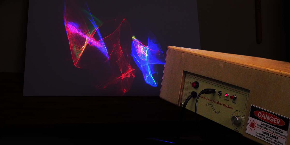
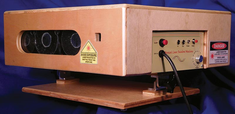
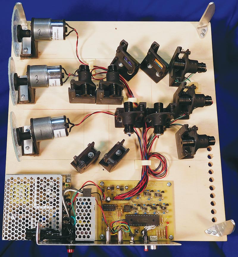
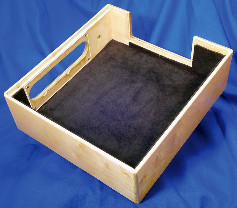
FIGURE 1. Outside view shows the control panel and laser aperture.
How It Works
It’s five inches tall (7.5” with stand), 14 inches wide, and 15 inches deep, and is made of wood, plastic, motors, and electronics. I directed the lasers through slowly rotating pieces of clear bumpy stained glass.
The music is divided into six different frequency bands which then control the brightness of the lasers. Two sets of red, green, and blue lasers combine into each of two beams with all three colors, and another separate laser shows a pure red beam.
I thought that the three beams combined would give me one color that is the sum of the three colors. Then, there would be three beams: one red, and two of some different colors. I was wrong, but it turned out even better than I hoped. I got rainbows!
The inexpensive laser diodes are not perfectly shaped round beams, so even lining them up nicely does not combine them perfectly. Also, the bumps in the stained glass separate the colors slightly, just as a prism separates white light into its component colors. The colors are programmed to change in response to the music, and the different patterns from different beams through different pieces of glass make shapes and colors change and evolve into moving rainbows. Check out the video below and see what it does with five different pieces of music. The video doesn’t capture the vividness of the colors or the unique character that laser light has, but it does give you a general idea.
The music is input through an op-amp mixer, combining right and left channels into one. A graphic equalizer display filter (MSGEQ7) analyzes the music and separates it into six frequency bands. A microcontroller (PIC18F4620 at 40 MHz) reads this information and puts it out through constant-current LED drivers (MAX16819) to control the lasers and make them individually reactive to each of the six frequencies. The code imparts a small delay in the decay of the laser light at the peaks, so that the lasers have a little more “sustain” than the music. This keeps the lights from being too jumpy and smooths out the display.
To combine the lasers, a green laser goes through an angled laser-combining filter/mirror that allows the green to pass, but reflects red. I’ll call it a mirror for this article. The red laser comes in from the side and the result is a combination of the red and green beams. This beam then goes through an angled mirror that passes the red/green beam, and reflects blue. The blue laser comes in from the side, and now the three beams are combined.
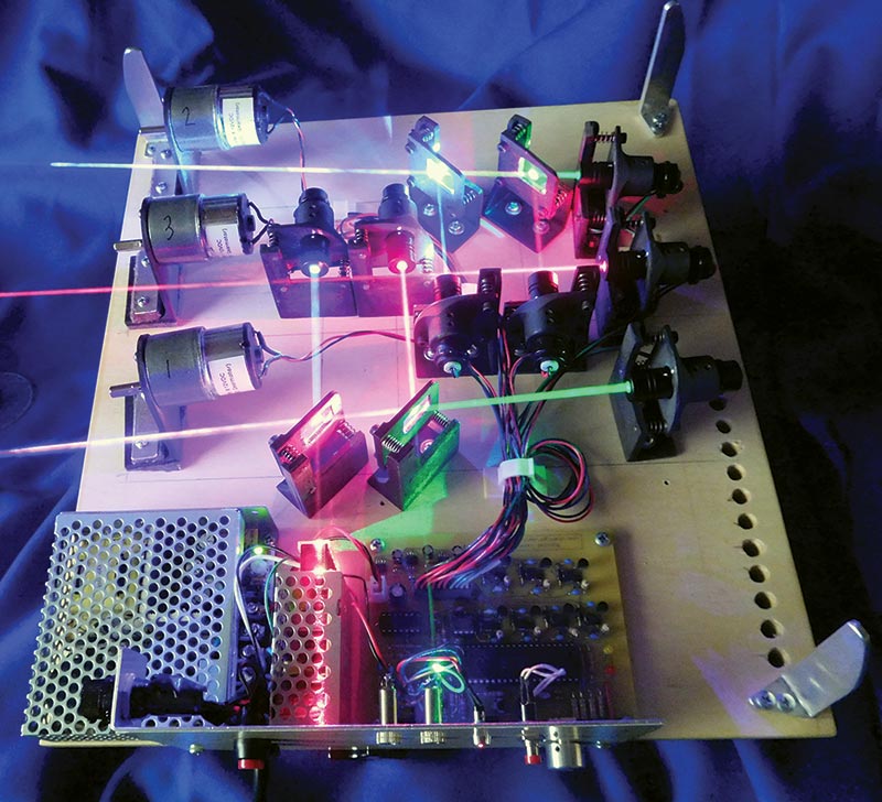
The laser beams can be seen by the use of smoke in Figure 2. The third beam is just red, since red is somewhat dominated by the blue and green, and I thought some red should stand alone in one beam.
FIGURE 2. The paths of the laser beams. Smoke makes them visible.
The three beams (two multicolored and one red) are shone through three disks of stained glass, which are slowly rotating and distort the beams into wonderful light patterns. I chose uncolored textured glass for its clarity and pattern, but you could experiment with other colors and patterns. The wave-like pattern on the glass that I used makes the refraction look a little like the waves of sunlight on the bottom of a clear ocean floor.
The video is filmed from a 4-1/2 ft distance to a wall 6-1/2 ft wide, from the left side of the screen to the corner of the room toward the right. Doubling the distance also doubles these dimensions and gives four times the area.
Music
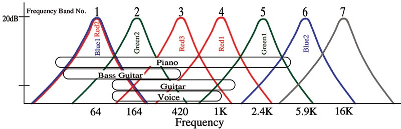
Figure 3 shows the frequency bands with the laser colors and the range of some instruments.
FIGURE 3. Frequency band distribution, with typical instrument's frequency ranges.
I found the seventh band to be so noisy that I couldn’t tell the music from the noise, and well above what most instruments are producing in pitch, so I left it out. I measured the frequencies with the components I selected, which are slightly different than the datasheet. Three combined colors appear projected on the left (which I numbered “1”); three more combined colors appear projected on the right (#2); and the solo red laser is in the middle (#3). The physical arrangement is shown in Figures 4 and 5.
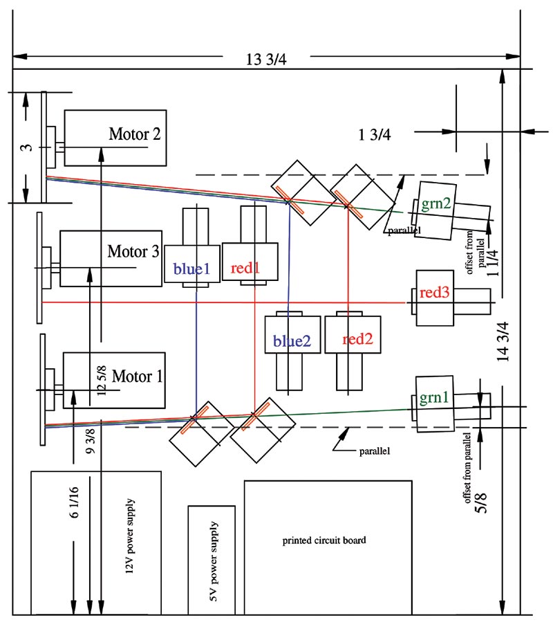
FIGURE 4. View from above.
FIGURE 5. Layout of everything, with some important dimensions.
The lowest band has the bass, the bass drum, and other lowest notes. This is where much of the rhythm resides, so some blue on the left and some red on the right allows the whole projected display to pulse with the beat. The solo red laser covers some midrange tones. The highest range that I am using (5.9 kHz) holds the treble notes, some percussion, and overtones of the other instruments. Since this includes much of the snare and cymbal sound, this is also an important part of displaying the beat.
While developing this project, I found the app “E-Scope 3-In-1” very useful. It’s free on the iPad and has a signal generator that allowed me to check the response of individual frequencies. You can also play a 10 kHz signal into your stereo and hear what you’re not really going to miss by giving up the seventh band.
Lasers
First, I should say that lasers can be dangerous. I made a small laser test circuit on a piece of perfboard, and was using it to test a blue laser. I had my laser safety glasses on, and was beaming it at a block of wood while trying the focus and brightness. Soon I realized there was smoke coming from the wood where the laser was burning it!
If you’re thinking of a laser light show, be aware that there are laws governing this. Permits, variances, and certifications need to be obtained, and the laws vary by state and country. The regulations are for commercial use of the lasers, so personal use is much less restrictive. If you’re using it for friends and neighbors, it’s not being sold by you, and it’s not used in an event where people pay admission, then you are often free of bureaucratic complications. The regulations aside, it’s always bad practice to fry your friend’s eyeballs.
While none of the lasers as used in this device will burn your skin, I imply nothing in the way of this being safe, and you should be aware of the danger involved. Also, use caution in avoiding looking directly at the laser beam, and perhaps even more caution is needed for reflection off a shiny surface that could bounce the beam into one’s eyes. The beam should always end at a light absorbing material or a diffusing screen, and not be directed randomly around the room where it can hit something shiny and reflective.
That said, there are ways to be safe. It can be made safer by keeping the cover on when it’s in use. These lasers are very bright, but they are throttled down in their intensity by limiting the current. The strong blue one is especially attenuated.
After the beams go through the glass disks, they become stretched out to cover a much larger area, and thus the intensity of any given spot is greatly reduced. Pulse Width Modulation (PWM) is used to control the intensity of the beams, and much of the time each beam is running at a fraction of its power.
It’s feasible that through amazing coincidence, a loud passage of music could turn on three lasers in one beam to a stronger intensity at the same time someone decides to look right at the laser. If a person’s eye happens to be in the exact location that the beams are together and intense, it could become possible for eye damage to occur. I suggest several things to protect yourself while setting this up. When you’re aligning lasers, set the selector switch so that the lasers are at a very low intensity. For operating the machine, a cover is necessary for the lasers and disks so that no stray beams can get into your eyes. Especially watch out for beams reflecting off of the back of the glass disks. Since the best glass for this is very lumpy on the outer surface and slightly wavy on the inner surface, the inner surface could reflect some light back at an angle in an unexpected direction.
Laser safety glasses are available. I have one pair to block red and green, and another to block blue. You can also view the lasers through a digital camera, as the laser light doesn’t come through the screen — only an image of the laser. The lasers shining off a diffused screen such as white foamboard or the wall is not dangerous but looking into the beam itself is. A shiny mirror-like surface can bounce the beam directly into your eye, and mirror-reflected laser light is nearly as dangerous as a direct hit.
When working on it, place it below eye level so you can see it with less chance of a beam going into your eye. In the machine’s final position, if it’s mounted above eye level and the projected beams are high enough on the wall so they also are above eye level, then nobody can get into a position of looking right at the beams coming out. A tall wall would be perfect for this.
An alternative would be to project onto a screen from behind. A label should be prominently displayed on the outside warning that lasers are involved. A sign at a local company that uses high power infrared lasers says: “Do not look into beam with remaining eye!” Check out Sam’s Laser FAQ (www.repairfaq.org/sam/lasersam.htm) for a ton of information on lasers and safety.
The laser diodes need to be mounted in the focusable housing/heatsink laser holders. Take the housing apart so you just have the inner brass diode holder. The diodes are press-fit into the hole in the holder. For me, the hole was a little too tight, so I filed it out a little until the diode would fit tightly, but not too tight. I used a drilled-out rod that was wider than the laser diode’s flange, and the hole inside allowed the diode’s pins to not have any pressure on them.
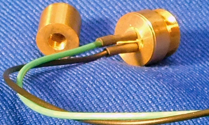
My diode pressing tube is shown in Figure 6. An arbor press was used to push the diode into the housing with the tubing, or a hammer can be used to gently tap it in. If it’s too loose, put a rod larger than the holder’s hole on the inside, take a smaller rod on the outside, and then with a hammer smash the edges of the hole a little. This will push some metal into the hole and tighten it up.
FIGURE 6. Laser diode mounted in a holder, and the metal pusher to get the diode into place.
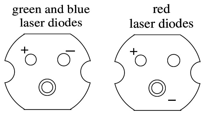
After pressing the diode onto the holder, the wire leads are soldered to the laser diode, using a heatsink on the pin near the diode to protect it. Notice from the diagram in Figure 7 that the pins are wired differently for the red than for the green and blue. I used black for negative, and the laser color for positive.
FIGURE 7. Wiring of the laser diodes.
When it’s put back together, a small drop of oil on the threads that go into the focusing collar helps when it comes time to adjust everything. When it was focused, I put some drops of paint on the collar and the housing to remember where it was.
I aligned the beams with the disks removed from their motors, so that the lasers are hitting the wall. Intensity is set low. A 20” x 30” piece of white foam board makes a nice display and setup screen for projection from two feet. (Figure 5 shows the placement of everything.)
The motors were placed on the mounting board first. Then, back lasers were mounted on the board (two green and one red). Make sure they’re going in the right direction and hitting the right location on the disk by holding up some paper to make sure the beam hits the right place — preferably while wearing safety glasses.
The outer laser beams are placed at an angle so that the pattern diverges as it gets farther from the projector, and the patterns don’t end up on top of each other. A line was drawn on the board that goes under each laser beam, which helps keep track of the beam’s location when everything is off. I put a pass-green/reflect-red mirror at a 45 degree angle with the green beam going through the middle. I marked the holes, then drilled and screwed the mirror bracket to the mounting board. The red laser is mounted so that it aims at the mirror.
Now, the adjustment screws can aim the red laser at the spot where the green laser goes through, and then the mirror’s adjustment screws can be used to line up the dots projected on the wall or paper. The beam’s spots on the mirrors are difficult to see at this low intensity, so I didn’t wear the safety glasses for this.
As mentioned, extra caution should be exercised for where the beams will hit so that they don’t make contact with a shiny surface. With everything screwed down, careful placement will have the beams directed down where they won’t hit anyone’s eyes.
Once you’re sure a beam can’t bounce directly into an eye, there is a slightly brighter setting that will help to see it better. Breathing on the mirror will fog it up and allow you to see where the beam is hitting. I placed the blue-reflect mirror in the same manner. All three beams are now aligned.
Once the glass disks are fastened onto the motors, a cover (Figure 8) should be in place so that everything inside is shielded from view.
FIGURE 8. Inside the cover, with the blanket fleece lining and the acrylic window.
A final focusing and aligning of the mirrors can be done while looking at the patterns on the wall. After the beams were aligned in the mirrors, alignment adjustments are made only with the mirrors, and not the lasers. Focusing the laser on the glass disk is different from focusing at a distance. The intensity is set at dim with all lasers on (Program 13). A cover over only the glass disks protects your eyes from what bounces off the back of the disk.
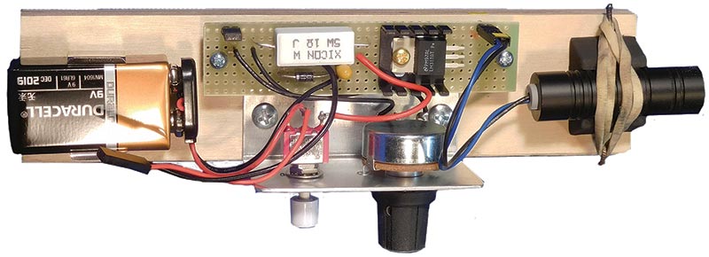
A laser test circuit (Figure 9) was made to get some of the details ironed out on how the lasers worked. It’s not essential for this project, but it enabled me to be sure I got the lasers working correctly before connecting them into the main circuit. It uses an LM317 as a constant current driver, and has a potentiometer to adjust the intensity of the beam. Some header pins allow an ammeter to be connected, and a shorting block is used to short these pins when an ammeter is not being used.
FIGURE 9. The laser tester.
This circuit is shown near the main circuit in Figure 10. The green laser may not work with the 9V battery; a 12V supply is needed for it, and it will still be rather dim using this circuit. The battery is removed when hooking the circuit to 12 volts. The laser tester is useful to take to the stained glass store and pick out pieces of glass, or a laser pointer can be used for this.
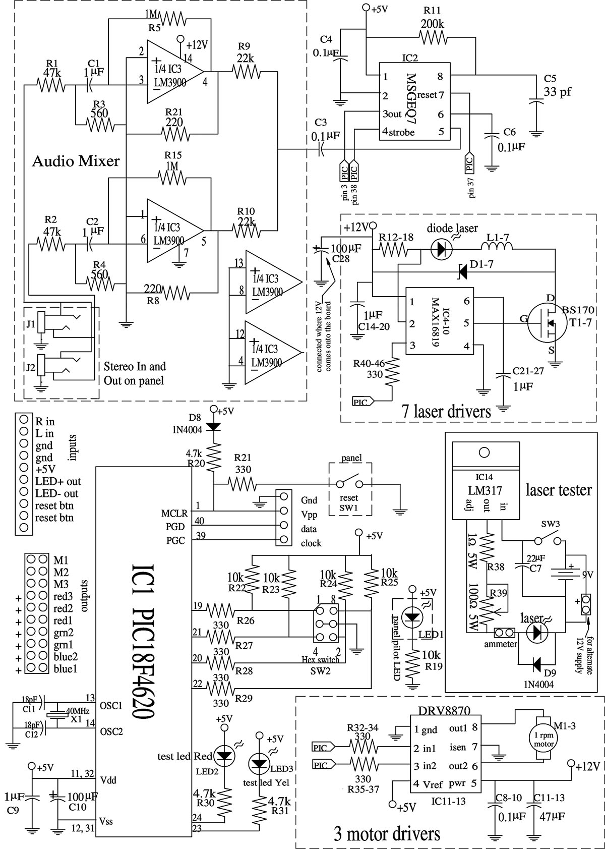
FIGURE 10. The circuit diagram.
Electronics
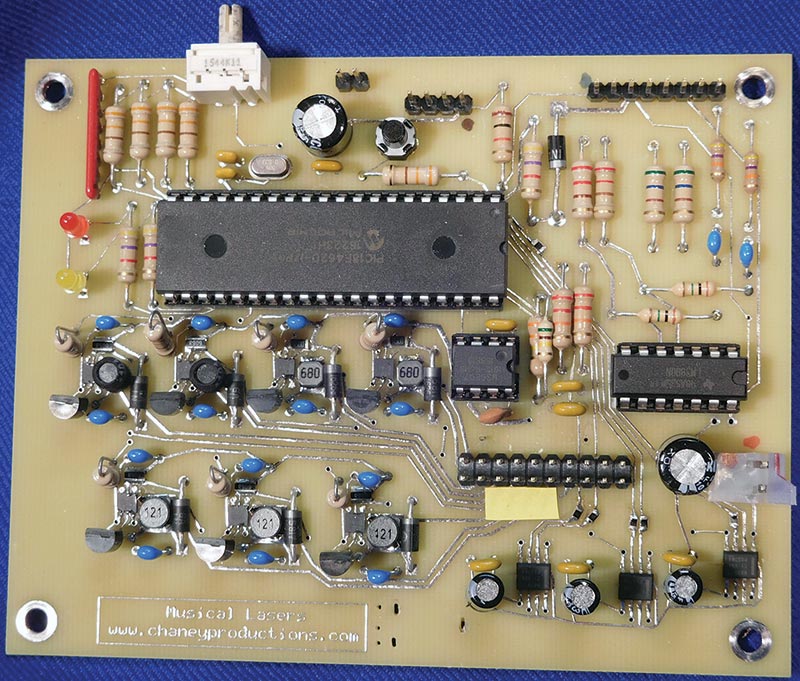
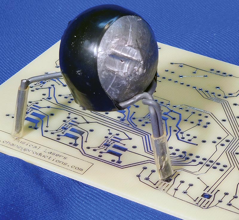
Some of the components are only available in surface-mount (SMD) packages. I designed a printed circuit board (PCB; Figure 11) for expresspcb.com to make for this. I consider myself relatively inexperienced at surface-mount soldering, but this was the only way to do it. I used through-hole components where I could.
FIGURE 11. The wired circuit board.
If you’re intimidated by SMD soldering, look at some YouTube videos (search: SMD soldering), get some flux, tiny solder wire and a tip, some type of magnification, and dive in! It’s not that bad.
There are a few SMD resistors for space considerations, but if you make it through the LED controllers and the motor controllers, then the resistors are easy in comparison. I made a little “hold-down” device with a 6 oz lead fishing weight, steel wire, and plastic tubing (Figure 12) that helped me a lot for getting the first contact of each part soldered. The SMD LED driver and motor controller chips are soldered through the hole from the bottom of the PCB so that they are connected to the pads at the top and bottom for heat dissipation.
FIGURE 12. SMD parts "hold-down" of wire and fishing weight.
The lasers are driven by constant-current LED drivers. The circuit diagram has one driver circuit, and the table shown in Figure 13 holds the values for the individual parts of the circuit for each laser. The laser drivers are supposed to have the components close together, so the 330Ω resistors are mounted on the end to get them in tight.
LED (Laser) Driver Parts
Laser
PIC Pin
IC
Intensity Resistor
Value (ohms)
Inductor
Inductor Value (µH)
Input Resistor
Pin 1 Capacitor
Pin 6 Capacitor
Blue1
33
IC4
R12
0.5
L1
68
R40
C14
C21
Blue2
27
IC5
R13
0.5
L2
68
R41
C15
C22
Green1
26
IC6
R14
0.909
L3
100
R42
C16
C23
Green2
25
IC7
R15
0.909
L4
100
R43
C17
C24
Red1
34
IC8
R16
0.909
L5
120
R44
C18
C25
Red2
29
IC9
R17
0.909
L6
120
R45
C19
C26
Red3
28
IC10
R18
0.909
L7
120
R46
C20
C27
FIGURE 13. Table of values for the seven LED laser driver circuits.
Some of the components are very sensitive to static electricity. I used a bench anti-static soldering mat, a grounded soldering iron, and a grounding wrist strap for the placement of all the components. In theory, once everything is soldered in place, the parts are not quite so sensitive.
The motors are speed controlled with DRV8870 chips. I originally thought I would vary the speed and direction of the motors with the music for even more variation in the display. It turns out that the motors do not respond fast enough to tell that any changes are due to the music. The lasers are so responsive to the music that changing the motor speed and direction is not really needed.
Although it may work without speed control to some extent, I found that being able to set the motor to the best speed is important. Different types of glass will look better at one speed than at others, so it was useful to be able to set the speed for each glass wheel.
The speed that is important is really the number of inches per minute that the glass is going by the laser. This is a function of the speed of the motor, but also the distance from the center of the disk (radius) that the laser beam hits. This may be found by the formula:
I’m using glass speeds of 2.9, 1.8, and 5.5 inches per minute for motors 1, 2, and 3, respectively. Adjusting the speed of the glass is very helpful to get the best out of each piece of glass. Adjusting the motor speed is the easiest way of doing this, since you just need to change one number in the code. Adjusting the position of the motors/disks will work to some extent.
To make the design for the front panel, I drew it first with my computer using TurboCAD for Windows. I printed it on photo paper, and then laminated it with 3 mil plastic. I used Grafix double tack archival film to stick the design to the aluminum panel. The Grafix film was also useful to make laser warning labels to stick on the outside of the box. This was inspired by a great Instructables article, called “Make Your Own Front Panels.”
My front panel design is available with the downloads for this article. The circuit board is mounted on 3/16” spacers off the mounting board, and then the shaft of the hex switch lines up with the hole in the front panel.
Mechanical Things
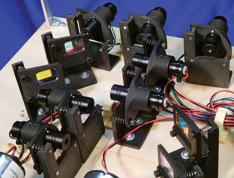
I printed brackets for the mtors, spindles for the glass disks, the laser brackets, and the laser mirror brackets with a 3D printer using ABS plastic. The laser and mirror holders can be seen up close in Figure 14.
FIGURE 14. Close-up of laser and mirror mountings.
If I didn’t have the printer, I would have made them out of 0.050 inch thick sheet brass, which is easy to cut, file, bend, drill, tap threads, and solder, and could be made to do the same thing.
I created the plastic parts with Autodesk Fusion 360, which is an excellent free program. The references for files for designing and making these parts can be found in the Resources sidebar. The .stl files that you can put directly into slicer software (such as Cura) are also available with the article downloads.
Each laser and mirror is adjusted with three 6-32 Allen cap screws, and springs hold the tension on the pieces. The lasers and mirrors can then be adjusted in two directions. I recommend a ball-end Allen wrench, which can engage the socket on the cap screws from a wide angle of directions and helps you get in there to make any adjustments.
Where the adjustment screws go through the moveable laser holders and mirror holders, it’s possible for the plastic to bind on a screw thread where the spring will not overcome this. I put a #26 (0.147”) drill into those holes. While spinning the drill, I moved the electric drill’s body in a circular manner to widen the holes at the outer edges. When adjusting these to aim mirrors or lasers, the adjustments will be most reliable if done while tightening the screws.
If the screw is tightened past the best point, it is backed up and done again until the best point is reached while tightening. This will keep the moving part from catching on a thread and then loosening later when the whole thing is jarred. My first adjusters used springs that were a little thin, and jarring the machine could knock the lasers out of alignment. The lasers are each held in their holders by two 6-32 Allen setscrews. The glass disk mounting spindles are held to the motor shaft by 6-32 setscrews. There are holes in the brackets and spindles that need to be drilled out and threaded for the 6-32 screws. I use a #36 drill (0.106”), and a “gun tap.”
A gun tap is for through-holes, has two flutes, and pushes the cuttings out the far end of the hole. You can chuck it in your electric drill, and motor the tap into and back out of the hole in short order. Other taps will load up with the cuttings and must be slowly cranked in and out by hand in tiny steps to avoid the cuttings jamming it all up. For brass, use a little cutting oil; ABS plastic doesn’t need it.
The mirrors are held in their holders by tiny spots of silicone sealant at the corners. Notice that the mirror holders for lasers blue1 and red1 are a mirror image to the holders for mirrors blue2 and red2. This way, the supports and adjusting screws stay out of the way of the laser beams. The motor brackets have larger holes in the base than seems necessary for the mounting screws. This gives some room to move the glass disks a little to get some different angles. For some disks, changing the angle a little can improve the patterns generated. Also, there is room in the holes for the mounting screws to not touch the edges of the holes.
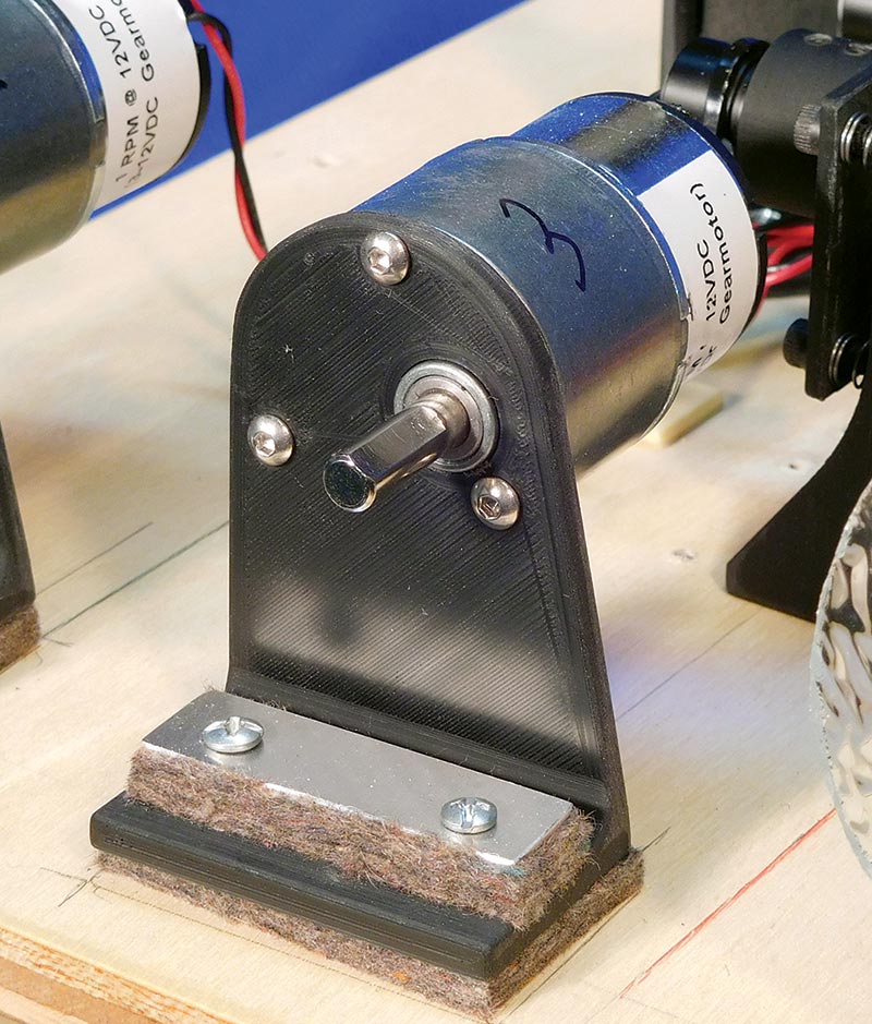
The motor brackets need to be acoustically insulated from the mounting board as shown in Figure 15. Otherwise, the vibrations of the motor go into the mounting board which acts like a sound board, and the noise of the motors is too loud. A 1/4” piece of felt goes under the bracket; another piece of 1/4” felt on top of the bracket’s foot; and a small piece of 1/16” aluminum over that creates a cushion for the motor bracket. The felt pads dampen the vibrations nicely.
FIGURE 15. Motor mount, with felt sound-dampening spacers.
The 3” glass disks come from a stained glass supplier. I recommend going to a store and try shining a laser through different pieces of glass while moving the laser very slowly along the glass. Be sure to shield your eyes from reflections off the back side of the glass, and just look at the patterns on the wall or floor coming from the front of the glass.
The best varieties of glass are very lumpy on one surface and wavy on the other. Different kinds of glass produce different kinds of patterns, and it’s nice to have several kinds among the three pieces. Sometimes one piece of glass looks the best in the store but isn’t as good as others when put in very slow motion by a motor.
I picked up 2-3 disks each of four different types of glass, glued them to the spindles, and tried them out. If a single dot of laser beam makes it through the glass without being dispersed into a pattern, then that piece of glass is not lumpy enough.
The spindles are glued to the smoothest side of the disks with silicone sealant/glue. If you don’t want to cut the glass yourself, bring it to a glass store with a bunch of 3” paper circles and ask them if they will do it for you. They can glue the circles onto the glass to help cut them out. Compared to making stained glass creations, cutting circles is a piece of cake.
They’ll use a wet diamond glass grinder to smooth the sharp edges or you can do it with wet carborundum sandpaper. There is also lumpy glass available for bathroom windows and shower doors. Some of it is tempered, thick, and very difficult to cut. A stained glass dealer will have many more varieties of very useful glass.
My mounting board and outer cover are made of 1/2” thick plywood. The big window for the lasers is covered on the inside with 1/8” acrylic, with two 1/2” holes placed out of the laser paths for ventilation. The acrylic helps make it quieter.
I lined the inside of the box with thick black blanket fleece to absorb the light and sound, and make the motors quieter. Another hole in the wood allows me to plug in my PIC programmer while the cover is on. There are also some ventilation holes in the mounting board.
After operating my machine at room temperature for an hour, the electronics inside feel barely warm enough to detect with my fingers. There are aluminum guide posts at three of the corners of the board, so I’m less likely to bump something out of alignment when placing or removing the cover. They aren’t necessary if you’re very careful, but I took the cover on and off a lot of times during development and it sure was handy.
Programming
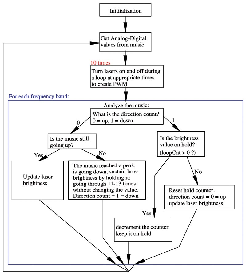
The flowchart in Figure 16 outlines the music program. I programmed it with PICbasic Pro, and a little bit of assembly language. I like the ease of use of the PICbasic language, and the low cost of the chips. This microcontroller is very fast, and can give a PWM display that is fast enough to not give an appearance of “flicker.” I tried to liberally add comments to my code, to help you figure out what is happening.
FIGURE 16. Flowchart of music programming.
First, by way of a 16-position switch, a program is selected (Figure 17). There are three programs with music driving them at three different intensities.
Program Selector Switch
Program
Function
0
Music, dim intensity
1
Music, medium intensity
2
Music, bright intensity
3
No Music, dim intensity
4
No Music, medium intensity
5
No Music, bright intensity
6
example of my number measurement routine
7
lasers very bright, no motors, for smoke photos
8
unused
9
3 motors on fast, to get the screws around for loosening
10
RGB lasers #1 on dim for setup
11
RGB lasers #2 on dim for setup
12
all lasers on very low for testing, motors on, no music
13
all lasers on low for testing, motors on, no music
14
all lasers on very low for testing, motors off, no music
15
all lasers on low for testing, motors off, no music
FIGURE 17. List of programs selected by the rotary switch.
There are three programs that make a laser show without music controlling it (also at three different intensities). There are other programs for setting up the system. Having a number of programs made setting all of this up easier, and was also helpful in determining frequencies and amplitudes in the process of getting it all to work. The different switch positions combined with the red and yellow LEDs on the board made it possible to discover a lot about how the program was working, and to find the levels of noise and maximum amplitude as a function of frequency. Program 6 gives an example of what I did to find this. Now that the machine works, the switch is convenient for making different display programs and setup routines.
When a program to make musical displays is chosen, the first step is to retrieve the data from the graphic equalizer display filter by analog-to-digital (A-D) conversion. Each channel’s level is a brightness number for determining what to do with the lasers. This brightness level is then remapped through a lookup/lookdown process to remap the values. Below a value of 25 is noise, so this is all assigned a value of zero, and the rest of the values are reassigned to new numbers. Some bands are not bright enough, so they get a boost. All of this is done so that each color/frequency-band/laser gets a more equal treatment as far as the amount of light from the laser for each channel. There are three different sets of color maps for dim, normal, and bright intensity programs.
The brightness values for the lasers are put into a small loop that turns on each laser for a fraction of time, which determines the intensity of the color using PWM. The small loop repeats 10 times. When a value of the frequency band reaches a peak, the intensity number is not refreshed for several times through the big loop to add more “sustain” to the colors. It is fast enough to catch the beats, and this delay in the intensity decay keeps it all from being too jumpy. The whole thing repeats inside a bigger loop, starting again with the A-D value retrieval. The values are refreshed in the bigger loop about 60 times a second, and so the lasers are flashed about 600 times a second.
This was a very fun project to build. I love how the colors express the different passages in the music. The colors and the laser coherent light are really beautiful. Lasers produce a kind of light that is different from others, and its unique character defies description on paper or visualizing in video. The interference patterns cause moving bands of color, accentuating the rainbow effect. The Musical Laser Rainbow Machine brings a new visual dimension to music. NV
Victor Chaney is a dentist by day and a maker/electronics enthusiast in his spare time. He has a degree in Physics, but much of his electronics knowledge has been self-taught with a lot of help from the internet and books. He plays in a country/rock band on weekends. Previous articles in Nuts & Volts are “H-2-Opus” (June 2003) and “The Flying Marbellos” (December 2005). His website is www.chaneyproductions.com, and you can reach him by email at [email protected].
I would like to thank my daughter-in-law, Eli Fox Chaney, for her help in editing the text of this article.
Parts List
Part
Value
Qty
Type
Part Number
Supplier
R1, R2
47K Ω
2
1/2 watt resistor
R3, R4
560 Ω
2
1/2 watt resistor
R5, R15
1M Ω
2
1/2 watt resistor
R9, R10
22K Ω
2
1/2 watt resistor
R8, R21
220 Ω
2
1/2 watt resistor
R11
200K Ω
1
1/2 watt resistor
R12, R13
0.5 Ω
2
Surface-mount resistor 1206
331-0.5LWCT-ND
digikey.com
R14-18
0.909 Ω
5
Surface-mount, lW, 0612
541-2511-1-ND
digikey.com
R21, R26-29, R40-46
330 Ω
12
1/2 watt resistor
R20, R30, R31
4.7K Ω
3
1/2 watt resistor
R19
10K Ω
1
1/2 watt resistor
R22-25
10K Ω
1
Resistor strip
4608X-1-103LF-ND
digikey.com
R38
1 Ω
1
SW wirewound resistor
660130
jameco.com
R39
100 Ω
1
SW potentiometer, linear
140514
jameco.com
R32-37
330 Ω
6
Resistor SMD, 1/4W
311-330ECRT-ND
digikey.com
C1, C2, C9, C14-27
1 µF
17
Disc ceramic capacitor, 25V
445-173583-1-ND
digikey.com
C3, C4, C6, C8-10
0.1 µF
6
Disc ceramic capacitor
544921
jameco.com
C7
22 µF
1
Tantalum capacitor 16V
545852
jameco.com
C11-13
47 µF
3
Electrolytic capacitor, 35V
1945428
jameco.com
C10, C28
100 µF
2
Electrolytic capacitor, 25V
330740
jameco.com
C29, C30
18 pF
2
Disc ceramic capacitor, 50V
BC1004CT-ND
digikey.com
C5
33 pF
1
Disc ceramic capacitor
BC1007CT-ND
digikey.com
L1, L2: Inductors
68 µH
2
Inductor, SMD
SRN4018-680MCT-ND
digikey.com
L3, L4
100 µH
2
Inductor
RLB0608-101KL-ND
digikey.com
L5, L6, L7
120 µH
3
Inductor, SMD
PCD1358DKR-ND
digikey.com
ICl: PIC18F4620
1
Microcontroller
PIC18F4620-I/P-ND
digikey.com
IC2: MSGEQ7
1
Graphic eq. disp. filter
COM-10468
sparkfun.com
IC3: LM3900 op-amp
1
Audio amplifier
24168
jameco.com
IC4-10: MAX16819
7
Constant current LED driver
MAX16819ATT + TCT-N D
digikey.com
ICll-13: DRV-8870
3
Motor driver, SMD
296-42660-1-ND
digikey.com
IC14: LM317
1
Adjustable regulator
192268
jameco.com
Dl-7
7
Schottky diodes, 20V, lA
1N5817RLGOSCT-ND
digikey.com
D8, D9
2
1N4004 diodes
35991
jameco.com
Ml-M3
3
Gear motors, 1 RPM
638150
servocity.com
Xl
1
40 MHz crystal
XC1769-ND
digikey.com
SWl, SW2: Switches
2
Momentary pushbutton
26623
jameco.com
SW3: Hex rotary switch
1
Rotary DIP hex switch
GM7262-ND
digikey.com
SW4: Power switch
1
Pushbutton SPST
164494
jameco.com
Tl-7: B5170
7
MOSFET T0-92 transistor
1217519
jameco.com
Jl, J2: Stereo audio jack
2
3.5 mm stereo jack, female
SC2590-ND
digikey.com
Red laser diodes
3
Mitsubishi LPC-840 650 nm
322910534230
ebay.com
Green laser diodes
2
OSRAM LD PL520 520 nm
381195527655
ebay.com
Blue laser diodes
2
OSRAM PLTB450B 450 nm
331385061153
ebay.com
Laser diode holders
7
Focusable housing/heatsink
190994318510
ebay.com
Power supply, 5 VDC
1
5V, 3A
1919043
jameco.com
Power supply, 12 VDC
1
12V, 4.2A
323396
jameco.com
Four-pin header
1
Cut 4 and 10 from 20
2229036
jameco.com
10-pin header
1
See above
"
jameco.com
Double 10-pin header
1
53480
jameco.com
.156" header, two pins
1
Cut to two pins for 12V
879887
jameco.com
.156" housing, two pins
1
Cut to two pins for 12V
104433
jameco.com
.156" crimp pins
2
736544
jameco.com
Fuse holder
1
Panel mount
18703
jameco.com
Fuse, lA
1
10373
jameco.com
Laser beam combiners
2
Reflect/pass beams
262721209424
ebay.com
Heatsink for LM317
1
Heatsink
70658
jameco.com
Laser safety glasses
1
Green/blue blocking
381343636062
ebay.com
Laser safety glasses
1
Red blocking
381343636062
ebay.com
Wire comp. springs
33
.240 dia., 5/8" L, .020" wire
06810444
mscdirect.com
6-32 x 3/4" machine screws
33
Allen socket head
91251A151
mscdirect.com
#6 x 1/2" sheet metal screws
22
Mounting lasers & mirrors
90190A148
mscdirect.com
#6 x l" sheet metal screws
6
Mounting motor brackets
90190A153
mscdirect.com
6-32 gun tap
1
For threading holes
2523A446
mscdirect.com
6-32 x 1/8" setscrews
17
For lasers and spindles
91375A142
mscdirect.com
0.050" brass sheet
6X6"
If no 3D printer available
8956K445
mscdirect.com
7/64" Allen wrench
Ball-end, L-key
5503A17
mscdirect.com
Grafix double tack mounting film for panel and warning signs