These days, small single-board computers are very popular. Examples include the Raspberry Pi, BeagleBone Black, Arduino, and many more. This is a big change from the early days of microcomputers where the size was quite large (bigger than a bread box you might say).
So, I got an idea: Could an Altair-style (Intel 8080 compatible) computer be built the size of one of today’s small computer boards? Could it fit in the metal tin of a popular mint? Well, yes it can!
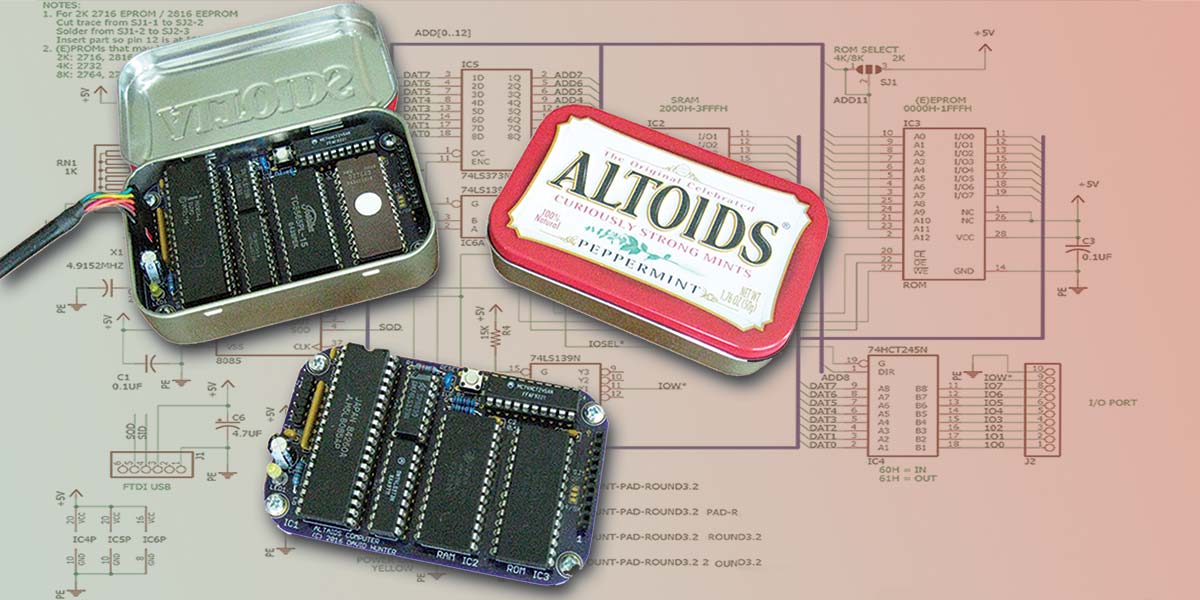
I present to you an Altair-style computer in an Altoids™ tin: “The Altaids Computer” (see Photo 1).
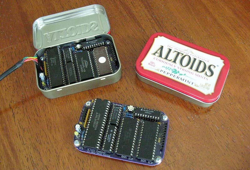
PHOTO 1.
In developing this computer, I wanted to use parts that would have been used in the late 1970s/early 1980s (so, no surface-mount!). Other features I wanted were that it should have a monitor for program development, include tiny BASIC, have a serial port, and at least one I/O port. In particular, I wanted it to run 8080 programs just like an Altair computer.
Hardware
The microprocessor used in the Altaids computer is the Intel 8085. It’s an improved version of the Intel 8080 that the Altair computer used. The 8085 runs off a single +5V supply and doesn’t require the support parts that the 8080 required. In addition, the 8085 has one serial in pin and one serial out pin that can function as a “bit-banged” (software) serial port.
A 4.9152 MHz crystal is used to generate a processor clock of 2.4576 MHz. I picked this frequency because it’s easy to derive serial baud rates from. It turns out, however, that wasn’t necessary, but after I got things working, I didn’t bother to change it.
Since I had several 8K SRAMs and EPROMs in my parts bin, they were chosen for the design. This resulted in the equivalent of a 16K Altair. While 16K might not sound like much today, it was a lot of memory back in the early 1980s. Rounding out the design, I added a little bit of logic for decoding and latching the address, plus an eight-bit I/O port. To provide a serial interface for user interaction, an FTDI USB to +5V serial cable is used. The USB cable also provides the +5V power to the computer.
The schematic is shown in Figure 1. It’s a typical 8085 design.
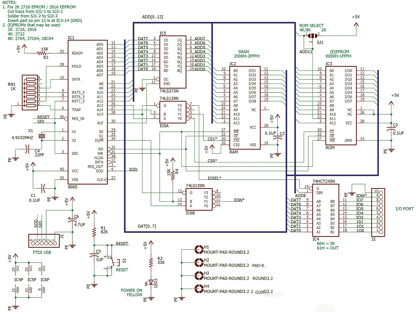
FIGURE 1.
The EPROM socket can be configured to support different sizes (2K or 4K and 8K) by changing a solder jumper. The default is for 8K EPROMs. To program the EPROM, I found a very inexpensive programmer called the MiniPro. The write line for the EEPROM is connected to the processor so it could be reprogrammed on the board, but I haven’t implemented software to do that.
As I mentioned, all these parts are still available these days. The part cost (not counting the tin and the PCB [printed circuit board]) is about $25. The suppliers I used were Mouser and Jameco. The full set of parts can be seen in Photo 2. The Parts List includes alternate parts (highligted in yellow) if availability is a problem.
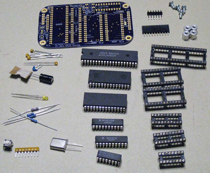
PHOTO 2.
The I/O port is a bidirectional eight-bit port with an output strobe on a 10-pin single row receptacle. For the I/O port hardware, I used a 74HCT245 buffer. Using an HCT part allows for interfacing to both TTL and CMOS signals. (An HCT part has a CMOS output but accepts a TTL level input [low = 0.8V, high = 2.2V].) It can also handle +3.3V logic signal inputs, although it will output +5V logic signals. Since the power available from a USB port is limited, I decided that external devices should have their own power supply. So, there’s no power output on the I/O port. The buffer also offers protection to the microprocessor data bus.
I first developed a prototype using wire wrapping to test the design out. Having done a prototype really helped the final board to work the first time. I then did a PCB design in Eagle. I was able to use a board outline that I got from the Adafruit Eagle library. The layout is quite dense, so I was unable to get all the traces and power supplies to fit on two layers. Therefore, I went to a four-layer design with the inner layers being ground and +5V.
This worked out well, and I can still make modifications to signal lines if there’s a problem. The layout (without layers 2 and 3) is shown in Figure 2.
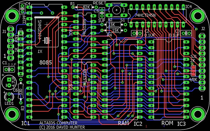
FIGURE 2.
A complete set of design files is available with the article downloads. I had the boards made at OSHPark and they turned out super nice. It was my first time using their services and I was really pleased. The price was very reasonable, and I got the boards in about two weeks. Their website was extremely useful because I could see what my board would look like after I uploaded the Eagle files. This really helped me fix the layout. After making fixes, I could re-upload the files and see if I had everything correct. This enabled me to get the boards right the first time.
The build is straightforward because only through hole parts are used. Most of the components are mounted to the top of the board. To fit in the tin with the lid closed, the crystal is mounted on the bottom of the board (see Photo 3). Sockets are optional, but I would recommend as a minimum a socket for the ROM.
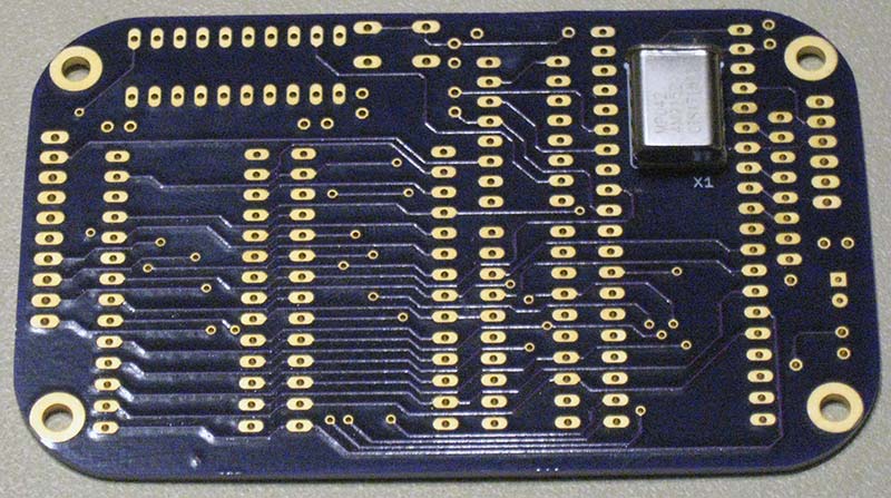
PHOTO 3.
The board uses 1/4” 4-40 spacers to keep from shorting out to the bottom of the tin. I found I needed to angle the board a little when inserting it into the tin. I didn’t mount the board to the enclosure. Instead, I used some foam weather-stripping on the lid to keep the board from moving around when closed up. A completed board assembly is shown in Photo 4.
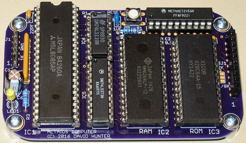
PHOTO 4.
Memory and I/O Addresses
The memory map for the Altaids computer is:
Address (hex) Device
0x0000 ROM
0x2000 RAM
0x4000 Unused
0x6000 Reserved
0x8000 Unused
The decoding for the I/O port is also decoded on the memory bus, so address 0x6000 is reserved. The input port is at address 0x60 and the output port is at 0x61.
Software
The original Altair used toggle switches to enter programs into memory and didn’t have a ROM. Because of the tediousness of this, EPROMs with monitor programs were very popular in the early days of computers that didn’t have disk operating systems. The computer would boot to the monitor program and communicate with a serial port.
A monitor program provides a user interface to replace the need for a front panel of lights and toggle switches. The Altaids monitor provides a set of commands for program development as seen in Screenshot 1.
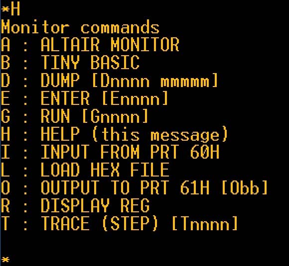
SCREENSHOT 1.
In addition, the EPROM contains an adapted Altair monitor, a typical 8080 monitor and Tiny BASIC. To communicate with the Altaids computer, I use a free terminal emulator called TeraTerm. It runs under Windows and provides a nice interface to the serial port. Also, the FTDI VCP (virtual communications port) drivers need to be loaded. The host PC communicates and powers the computer over the FTDI USB cable.
The serial port settings for TeraTerm are:
Serial interface: 2400 baud, 8N1, Flow control: None
Because of the time to process serial data by the Altaids computer, sending text files from TeraTerm requires delays for characters and lines. I found these transmit delay settings to be very reliable:
50 msec/char
200 msec/line
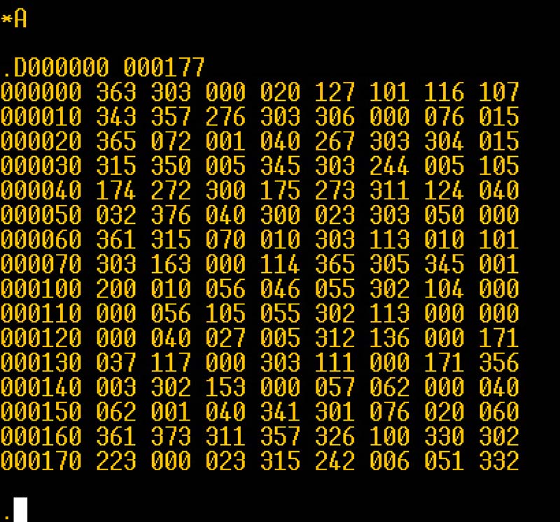
Entering “A” at the monitor prompt will start the Altair monitor. This is adapted from the Altair turnkey monitor (TURMON). This monitor was added to provide a “taste” of operating the Altair in “the old days.” An example session with the Altair monitor is shown in Screenshot 2.
SCREENSHOT 2.
The Altair has three commands:
Mxxxxxx - Change memory location xxxxxx (octal)
- Enter three octal digits for new data
- Press <SPACE> to skip to next location, any other character to exit
Dxxxxxx xxxxxx - Dump data (in octal) from start to end address
Jxxxxxx - Jump to location
All values are entered in octal with a space automatically sent when six digits are entered. Note, the D command was modified to be a more typical memory dump, where the original TURMON generated a punch tape format.
Entering “B” at the monitor prompt will start Tiny BASIC. This version of BASIC is based on the very popular Palo Alto Tiny BASIC (PATB). In the early days of microcomputers, BASIC provided a much easier programming environment over machine language. I’ve added some features to the original PATB, so I’m calling it “Palo Altaids Tiny BASIC.” Combined to the original PATB core are input and output commands, string handling, PEEK and POKE, and an improved random number generator.
Other additions are one-dimensional arrays using the DIM command.
Also included in this BASIC is the ability to load and save programs to a host PC using the Xmodem protocol which TeraTerm supports. With BASIC in ROM, about 7K of memory is available for programs. Another very handy feature added is a simple editor of BASIC lines. I don’t like having to re-type a line if I don’t have to.
In the Altair days, a line editor was very common and I found several that were written, but I definitely don’t like using them. (If you don’t know what a line editor is, be thankful!)
The editor provides a one-line screen using ANSI terminal commands (make sure TeraTerm is set for VT100 emulation). To edit a line, the command “EDIT linenumber” is entered. An editor prompt (“]”) is displayed, followed by the line to be edited.
You can use the left and right arrow keys to move through the line. Use delete/backspace to remove characters.
Characters typed will automatically be inserted at the cursor. The F1 key is used to exit the editor. The enter (return) key will clear to the end of the line and exit. While simple, the editor is useful and eliminates a lot of re-typing. The keywords and commands that BASIC has are shown in Table 1.
| DIRECT COMMANDS |
OPERATORS |
KEYWORDS |
FUNCTIONS |
| NEW |
+ |
REM |
RND |
| LIST |
- |
LET |
ABS |
| RUN |
* |
IF |
PEEK |
| EDIT |
/ |
GOTO |
USR |
| XLOAD |
= |
GOSUB / RETURN |
INP |
| XSAVE |
<> |
INPUT |
SIZE |
| BYE |
< |
PRINT |
FREE |
| RANDOMIZE |
> |
STOP / END |
|
| |
<= |
CLS |
|
| |
>= |
FOR / TO / STEP / NEXT |
|
| |
|
DIM |
|
| |
|
GET$ |
|
| |
|
PUT$ |
|
| |
|
POKE |
|
| |
|
OUT |
|
TABLE 1.
Screenshot 3 is an example of communication with the computer. It shows the sign-on message of the monitor and a sample session in tiny BASIC.
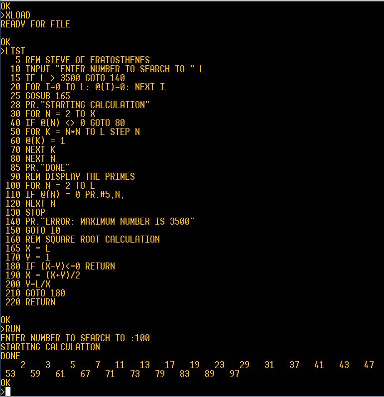
SCREENSHOT 3.
Most BASIC computers use a control-C input from the keyboard to stop the program. Usually, there would be an interrupt from the UART to the microprocessor to handle this. However, there wasn’t room for a UART in the tin. So, I had to recognize the control-C in another way. Since a control-C is 0x03 in ASCII, the serial data (LSB first) we would have available would be the bit sequence as shown in Table 2.
| Start |
Bit 0 |
Bit 1 |
Bit 2 |
Bit 3 |
Bit 4 |
Bit 5 |
Bit 6 |
Bit 7 |
Stop |
| 0 |
1 |
1 |
0 |
0 |
0 |
0 |
0 |
0 |
1 |
TABLE 2.
On the 8085, RST7.5 is an interrupt input that can detect a rising edge. So, I connected RST7.5 to the serial input. When the transition from the start bit to bit 0 occurs, the interrupt RST7.5 is triggered. The interrupt routine then captures the additional bits of the serial word. If the word is control-C, the BASIC restart is performed. Otherwise, it’s ignored.
I’ve noticed that sometimes “garbage” characters will show up on TeraTerm when I enter control-C, but they don’t hurt anything. With this interrupt routine, control-C can be used to stop a running program without having to hit the RESET button and start over. To keep normal keyboard input from causing interrupts, the interrupt is only enabled when BASIC is running (and not waiting for user input) or a program list is being displayed.
The other monitor provides typical commands for the era. Typing “H” will show a brief summary of the commands available. The usual dump, enter, and go commands are present. There are commands to input and output to the I/O port, as well as display the register values. You can also load a hex file using the “L” command. To help debugging assembly programs, a single step trace command is provided. With the trace running, a key press will execute a single instruction. The instruction and register values are displayed with each trace. Here’s an example of a single trace:
PC :SP :A SZ_A_P_C:B C :D E :H L
200B 3F02 24 00010100 1C05 15B8 2000 JMP 2000
Low-Level Programming
The primary function of the monitor is to allow low-level programming of the computer. This is either assembly or machine language. The original Popular Electronics article about the Altair (1975) included a simple demo program. I adapted it for the Altaids computer; the assembly listing is:
; DEMO.ASM
;
; ALTAIDS computer demo
; based on Altair demo from Popular Electronics, Feb 1975
;
; COMMAND TO ASSEMBLE:
; a85 demo.asm -l demo.prn -o demo.hex
;
;
2000 ORG 2000H
2000 3a 80 20 DEMO: LDA VAR1
2003 47 MOV B,A
2004 3a 81 20 LDA VAR2
2007 80 ADD B
2008 32 82 20 STA VAR3
200b c3 00 20 JMP DEMO
;
2080 ORG 2080H
2080 1c VAR1: DB 1CH
2081 08 VAR2: DB 08H
2082 00 VAR3: DB 0
2083 END
After assembling the program, the demo.hex file can be sent to the computer with the “L” monitor command. Screenshot 4 shows single stepping through the demo program. Each step shows the next program counter (PC) address, the current register values, and the assembly language of the next instruction at the PC.
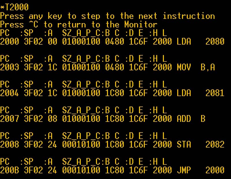
SCREENSHOT 4.
I/O Demo
To show how to use BASIC with the I/O port, a simple demo was built up to simulate the roll of a single six-sided die (like for a board game). The schematic is shown in Figure 3 and a photo of a hardware prototype on a solderless breadboard is shown in Photo 5.
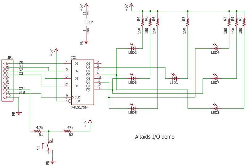
FIGURE 3.
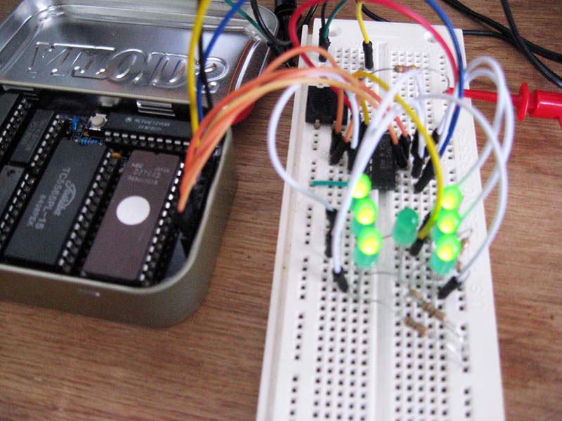
PHOTO 5.
A 74LS175 Quad D flip-flop is used to latch the output port data. A switch is read on the upper bit of the port. A series 4.7K resistor is added to keep bit 7 of the output port from being shorted to ground by the switch and possibly damaged. The BASIC program ROLLEM.BAS is:
1 REM DIE ROLL
5 PRINT “LET ‘EM ROLL”
10 IF INP(96) > 128 D=RND(6):GOTO 10
20 FOR I = 1 TO 30
30 D=RND(6):GOSUB 100
40 NEXT I
50 PRINT “ROLL=”,D:GOTO 10
99 REM DISPLAY DIE VALUE
100 IF D=1 OUT 97,1:GOTO 180
110 IF D=2 OUT 97,2:GOTO 180
120 IF D=3 OUT 97,3:GOTO 180
130 IF D=4 OUT 97,6:GOTO 180
140 IF D=5 OUT 97,7:GOTO 180
150 IF D=6 OUT 97,14
180 RETURN
200 END
Line 10 of the program polls the I/O port looking for the switch to be pressed. Calling RND() while polling helps to randomize the value even more since the random number seed updates every time the function is called.
If the pushbutton is pressed, line 10 is not executed and the program continues to line 20.
The program then runs through a loop at lines 20-40 to simulate the die rolling ending on a final value which is displayed in line 50.
The subroutine starting at line 99 outputs the roll to the latch on the I/O port that drives the LEDs.
The program shows some of the features of Palo Altaids Tiny BASIC. It also demonstrates how the I/O port can be used. Feel free to experiment! (There are some other programs included with the article downloads.)
One of the programs (IABENCH.BAS) is a benchmark program from (the now gone) Interface Age magazine. I modified it slightly for tiny BASIC.
Running the benchmark shows the Altaids performance to be comparable to other computers of the Altair era. (When run, it scored 1,694 seconds which placed its speed between the Sinclair ZX-80 [1631s] and the Processor Technology SOL-20 [1812s].) Check the website at https://archive.org/details/computermagazines to find an archive of computer magazines.
A host computer can be used for storing and loading BASIC files. The XMODEM (checksum) protocol is used to transfer files to a host computer. In TeraTerm, it can be executed under the menu File->Transfer->XMODEM and by selecting either Receive or Send. To save a program on the host computer, type XSAVE <CR> at the BASIC prompt. Then, perform an XMODEM Receive to a file. (I use *.TBI for an extension.)
These files are not text files but memory images, so they won’t look right in a text editor. To load a program from the host computer, type XLOAD <CR> at the BASIC prompt. Then, perform an XMODEM send of the desired tiny BASIC file.
For developing the ROM software, I used an 8085 assembler called A85. It’s available as a free download from www.retrotechnology.com/restore/a85.html#cug and works very well. There are many assemblers and simulators available online, so an assembler is not included.
Wrap-Up
I had a lot of fun working on this project. I hadn’t done any 8080/8085 assembly language programming in quite some time (I learned the 8085 in college), and it was fun to do it again.
The Altaids computer shows that retro-computing doesn’t need to take up a lot of space. If you want to relive the early days of computing with a small 8085 computer board, go out and build your own Altaids computer.
The 8085 has a much simpler assembly language to learn compared to modern processors. It’s also easy to design with, requiring only a single 5V supply. Interfacing to the processor is straightforward.
I hope I’ve shown that you can build a retro-computer that has useful capabilities such as Tiny BASIC without a lot of investment. Again, the schematic, PCB, and software files for this project are all included with the downloads. A complete kit (not including the mint tin) is available at https://store.nutsvolts.com/project-kits/sku17498. NV
Parts List
| Qty. |
REF DES |
Distributor P/N |
Distributor |
Description |
| 3 |
C1,C2,C3 |
75-1C10Z5U104M050B |
Mouser |
CAPACITOR, CER, 0.1 µF |
| |
|
332672 |
Jameco |
CAPACITOR, CER, 0.1 µF |
| 1 |
C4 |
75-1C10C0G220J050B |
Mouser |
CAPACITOR, CER, 22 pF |
| |
|
332541 |
Jameco |
CAPACITOR, CER, 22 pF |
| 1 |
C5 |
810-FK18X5R1E105K |
Mouser |
CAPACITOR, CER, 1 µF |
| |
|
544956 |
Jameco |
CAPACITOR, CER, 1 µF; Re-bend leads to 0.1” |
| |
|
545588 |
Jameco |
CAPACITOR, TANT, 1 µF |
| 1 |
C6 |
647-UVR2C4R7MED1TD |
Mouser |
CAPACITOR, ELECT, 4.7 µF, 160V |
| |
|
667-ECA-2CM4R7 |
Mouser |
CAPACITOR, ELECT, 4.7 µF, 160V |
| |
|
546071 |
Jameco |
CAPACITOR, TANT, 4.7 µF, 25V |
| 1 |
IC1 |
52062 |
Jameco |
MICROPROCESSOR, 8085 |
| 1 |
IC2 |
42892 |
Jameco |
SRAM, 8K x 8 |
| |
|
913-AS6C6264A-70PCN |
Mouser |
SRAM, 8K x 8 |
| 1 |
IC3 |
74827 |
Jameco |
EEPROM, 8K x 8 |
| 1 |
IC4 |
45031 |
Jameco |
74HCT245N |
| 1 |
IC5 |
47600 |
Jameco |
74LS373N |
| |
|
595-SN74LS373N |
Mouser |
74LS373N |
| 1 |
IC6 |
46623 |
Jameco |
74LS139N |
| |
|
595-SN74LS139AN |
Mouser |
74LS139N |
| 1 |
J1 |
153700 |
Jameco |
MALE HEADER, 1x6 |
| |
|
538-22-28-4063 |
Mouser |
MALE HEADER, 1x6 |
| 1 |
J2 |
2172560 |
Jameco |
FEMALE HEADER, 1x10 |
| |
|
649-75915-310LF |
Mouser |
FEMALE HEADER, 1x10 |
| 1 |
LED1 |
2155241 |
Jameco |
LED 3 MM |
| |
|
755-SLI-343Y8C3F |
Mouser |
LED 3 MM |
| 1 |
R1 |
660-MF1/4LCT52R823G |
Mouser |
RESISTOR, 82K, 1/4W |
| |
|
691323 |
Jameco |
RESISTOR, 82K, 1/4W |
| 2 |
R2,R4 |
603-MFR-25FRF5215K |
Mouser |
RESISTOR, 15K, 1/4W |
| |
|
691147 |
Jameco |
RESISTOR, 15K, 1/4W |
| 1 |
R3 |
660-MF1/4LCT52R331J |
Mouser |
RESISTOR, 330, 1/4W |
| |
|
690742 |
Jameco |
RESISTOR, 330, 1/4W |
| 1 |
RN1 |
652-4608X-1LF-1K |
Mouser |
RESISTOR NETWORK, SIP, 7POS, 1K |
| |
|
97826 |
Jameco |
RESISTOR NETWORK, SIP, 7POS, 10K |
| 1 |
SW1 |
162886 |
Jameco |
PUSHBUTTON, SPST, 4P |
| 1 |
X1 |
774-MP042 |
Mouser |
CRYSTAL, 4.9152 MHz, HC49U |
| 1 |
IC1-S |
41136 |
Jameco |
Socket, 40P 0.6” DIP |
| |
|
571-5-1571552-2 |
Mouser |
Socket, 40P 0.6” DIP |
| 2 |
IC2-S,IC3-S |
40328 |
Jameco |
Socket, 28P 0.6” DIP |
| |
|
571-2-1571552-9 |
Mouser |
Socket, 28P 0.6” DIP |
| 2 |
IC4-S,IC5-S |
38623 |
Jameco |
Socket, 20P 0.3” DIP |
| |
|
575-913204 |
Mouser |
Socket, 20P 0.3” DIP |
| 1 |
IC6-S |
37402 |
Jameco |
Socket, 16P 0.3” DIP |
| |
|
571-2-1571552-4 |
Mouser |
Socket, 16P 0.3” DIP |
| 4 |
H1,H2,H3,H4 |
761-2100-440-AL-7 |
Mouser |
Hex Female Standoff, 0.25”, 4-40 |
| |
|
133613 |
Jameco |
Hex Female Standoff, 0.25”, 4-40 |
| 4 |
H1,H2,H3,H4 |
2094389 |
Jameco |
Screw, Pan Head, Phillips, 0.25”, 4-40 |
| |
|
534-9900 |
Mouser |
Screw, Pan Head, Phillips, 0.25”, 4-40 |
Downloads
What’s in the zip?
Code Files
Eagle Design Files
Parts List