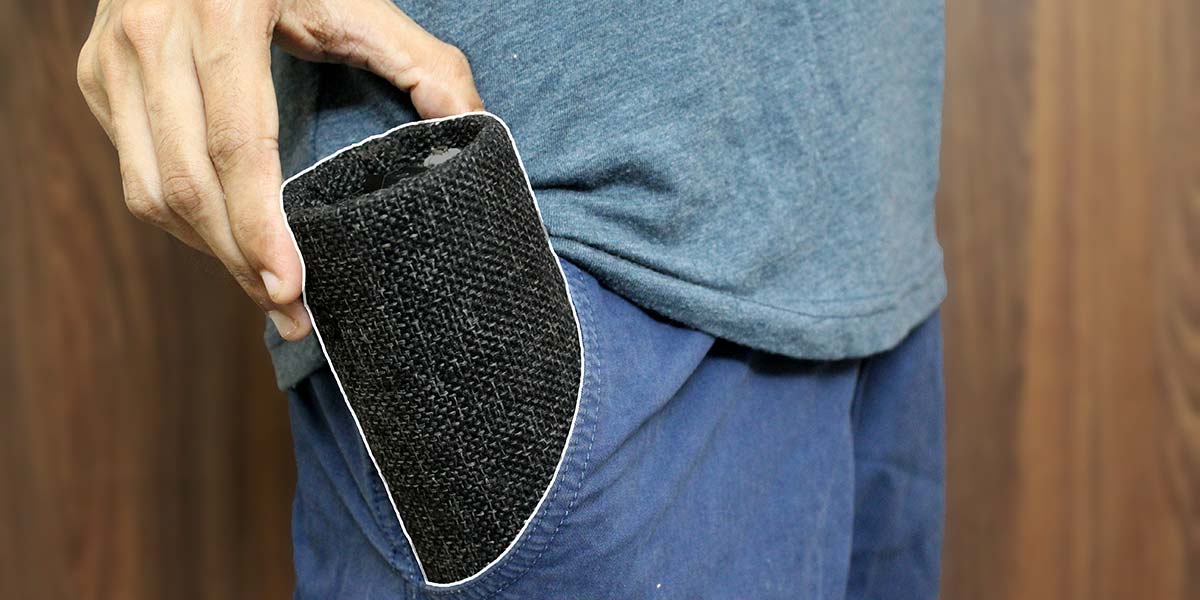
This project takes you through the build of a compact pocket-sized vacuum cleaner. It’s portable, convenient, and super easy to use. It includes features like powerful suction, reverse mode for blower, built-in nozzle storage compartment, and line-in mode to power from an external power brick. So, without any further ado, let’s dive into the build.
Design Overview
To have a cost-effective and robust design, most of the structures are made from cutting and forming standardized PVC pipe fittings. The finished product has a tubular design with a removable front head section (Figure 1 and Figure 2).
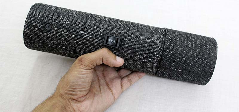
FIGURE 1. The finished vacuum cleaner.
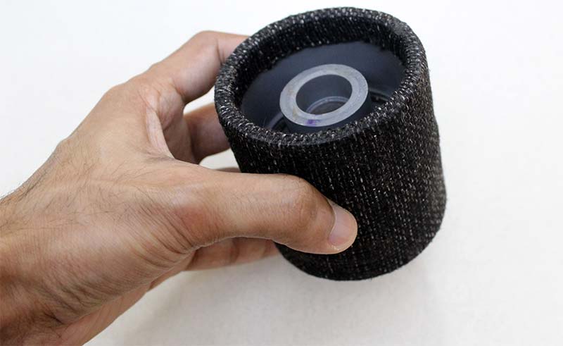
FIGURE 2. The removable front head section.
It collects all the dust and includes a separate compartment for storing nozzle attachments. This eliminates the burden of carrying the nozzles separately and helps reduce the chance of losing them. The nozzle compartment can be accessed by opening the cloth lid on the front head section (Figure 3).
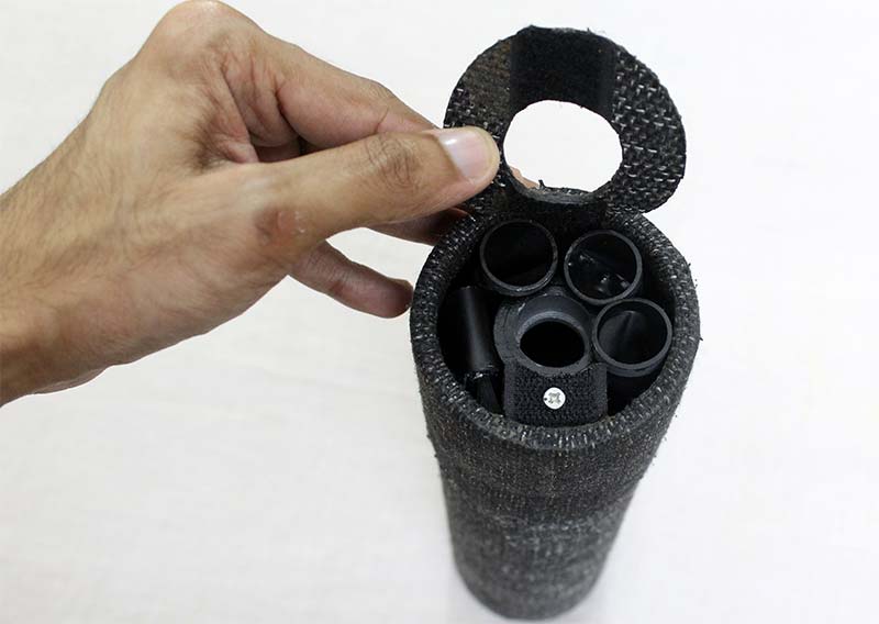
FIGURE 3. Nozzle storage compartment at the front.
The front head section is made by inserting a 1.5-0.5 inch PVC reducer inside a two inch coupler (Figure 4).
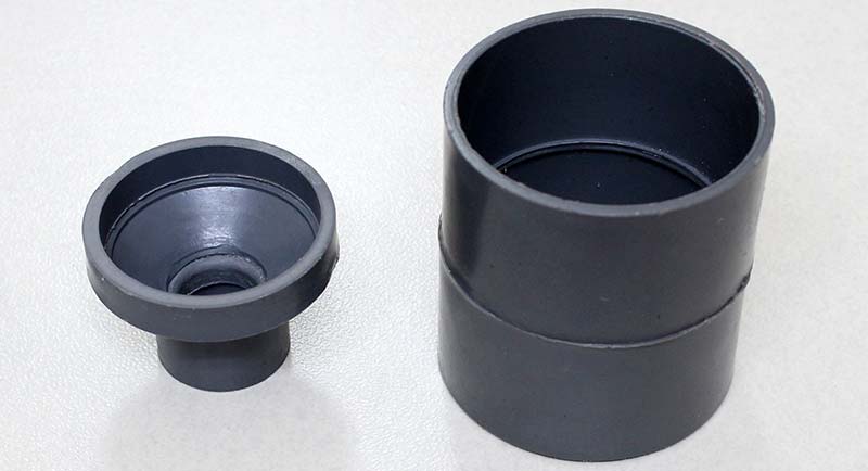
FIGURE 4. The PVC reducer (left) and the PVC coupler (right).
The reducer is held in place by drilling four holes along the surface of the coupler and then fixing it with bolts. The joint is further applied with epoxy putty for an air tight seal.
The reducer is fixed towards one end of the coupler so that it leaves some space on the other end. This space is later used to store the nozzle attachments; the dust particles are collected within the PVC reducer. For a better aesthetic look, a layer of black jute cloth is glued over the section and the excess cloth is trimmed with a hot soldering iron.
A two inch PVC pipe is now placed over a piece of the same jute cloth. By using it as a template, a circular section is cut out by running the soldering iron around the pipe (Figure 5).
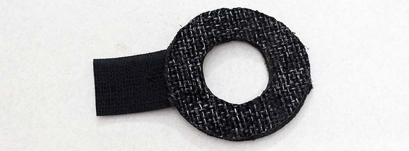
FIGURE 5. The circular cloth lid to cover the nozzle storage compartment.
This circular section is then fixed with Velcro™ strips on the front section. This acts as a lid to cover the nozzle storage compartment.
The nozzle attachments are made by warming a 0.5 inch PVC pipe with a heat gun and then applying some hand pressure (by using gloves of course!) to form the desired shape (Figure 6).
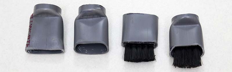
FIGURE 6. Three different nozzles and a cleaning brush (second one from the right).
Special attention should be given to make sure that only one end of the pipe is deformed to the nozzle shape. The other end should be totally isolated from the heat and deformation.
In short, this end should retain the same 0.5 inch diameter from the beginning. It helps to get a perfect fit while inserting it onto the PVC reducer within the front head section.
Three different nozzle attachments were made and one of them is fitted with a small brush using epoxy resin. The finished nozzles were given a small coat of black paint to avoid the raw look of the PVC pipe. These can now be stored in the empty space within the front head section while not in use.
The other portion on to which the front head section slides into is the main body section (Figure 7).
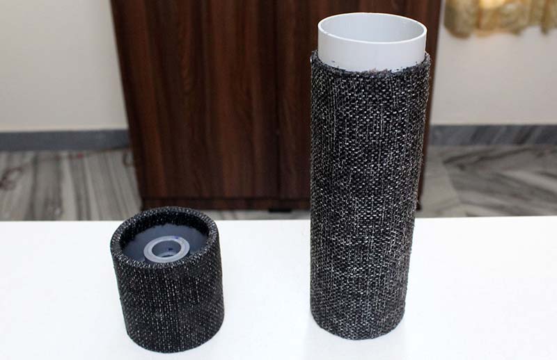
FIGURE 7. The main body section (right) and front head section (left).
t’s made from a two inch PVC pipe section having a length of 21 cm. The DC motor and the impeller (which creates the suction) are arranged towards its front (Figure 8 and Figure 9).
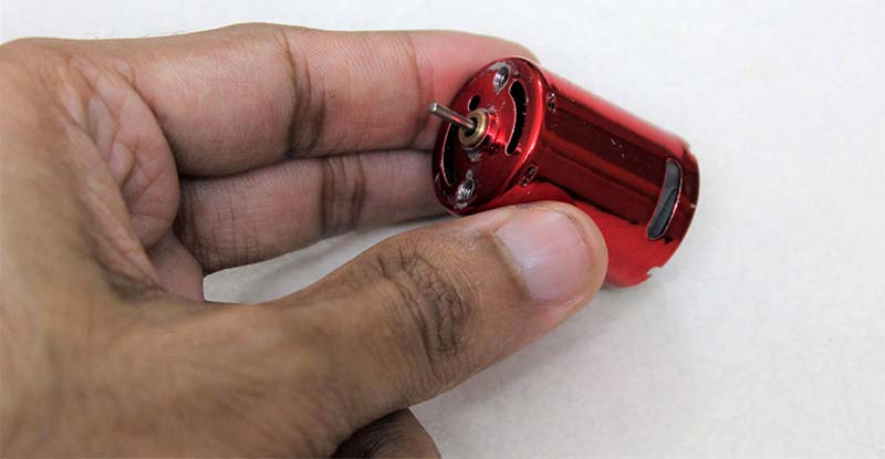
FIGURE 8. The DC motor which creates the suction.
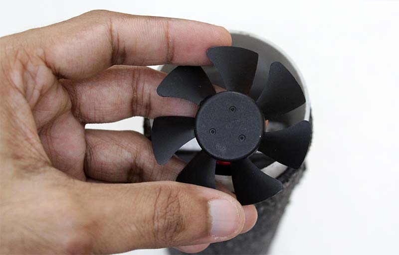
FIGURE 9. The impeller which is later attached on to the motor.
The other end of the main body section carries a DC socket for an external power supply, a micro USB port for charging, and a DPDT switch to toggle between vacuum and blower mode (Figure 10).
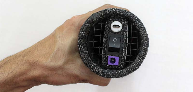
FIGURE 10. DC socket (bottom), DPDT switch (middle), and micro USB socket (top) at the rear side.
This section also consists of another DPDT switch towards the middle body (refer back to Figure 1). This toggles power between the internal battery pack and the external power supply via the DC socket. The main body section is also glued and covered with a black jute cloth just like the one we did before.
Electronic Components
The electronic components include two 18650 Li-Ion cells, a BMS (battery management system) module, a charging module, and a constant current/constant voltage (CC/CV) buck converter (Figure 11).
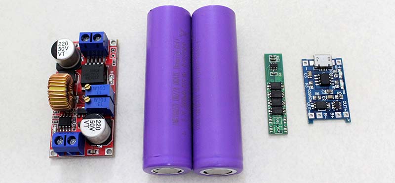
FIGURE 11. The CC/CV buck converter, two Li-Ion cells, the BMS module, and the charging module.
Wires were soldered from all the circuit terminals, so that it’s easy to make the connections at a later stage.
The components were arranged over a piece of fiberglass sheet and the outlines were notated with a marker (Figure 12).
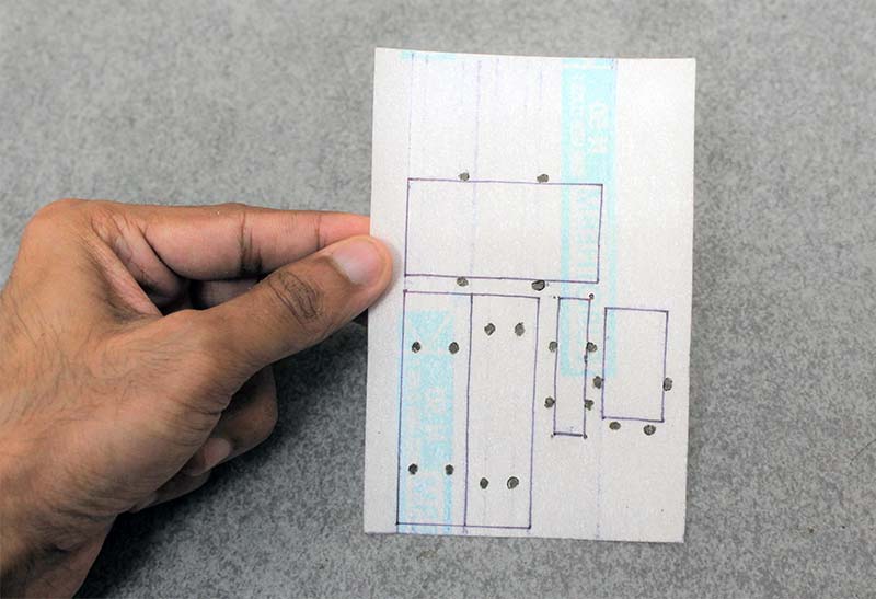
FIGURE 12. The fiberglass sheet onto which the electronic components are fixed.
Then, a few holes were made near the outline and zip ties were passed through. The components are now fixed onto the sheet by tightening them.
Zip ties were used because the components were lacking proper screw holes for the attachment — especially the Li-Ion cells, which were very easy to fix by this method.
Arranging all the components over the fiberglass sheet makes things more organized when installing it within the vacuum cleaner at a later stage (Figure 13).
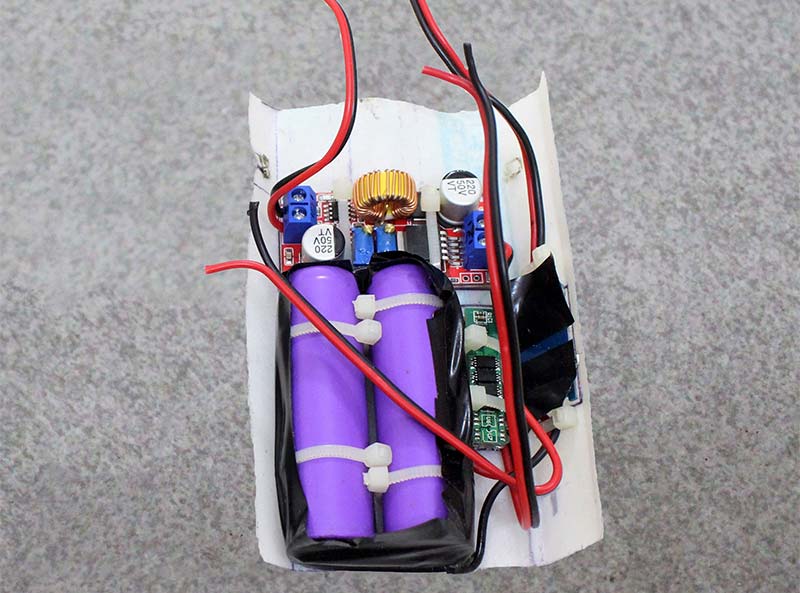
FIGURE 13. The electronic components fixed with zip ties.
Wire Connections & Terminals
Please refer to the wiring diagram while reading this section.
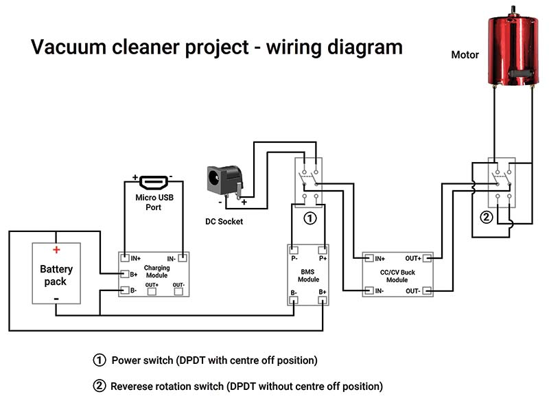
Wiring diagram
The 18650 Li-Ion cells have a capacity around 2,600 mAh and are connected in parallel fashion (1S2P). Using a battery spot weld is recommended for connecting the cells. Before connecting them, each cell should be fully charged with a charging module to keep both the cell voltages at the same value. This prevents the risk of uncontrolled charging between the higher voltage and the lower voltage cell. At a later stage of build, the exposed terminals are covered with an insulation tape to prevent any short circuits.
Talking about the charging module, it’s very convenient and easy to use. The B+ and B- terminals are connected to the positive and negative side of the battery pack. The IN+ and IN- terminals are the positive and negative charging input terminals. The out+ and out- are the positive and negative output terminals which drives the load; in our case, it’s the motor.
The output terminals are also equipped with the necessary safety feature of overcharge and undercharge protection of the battery pack. However, the output terminals are not rated for the higher current requirement of the motor. Hence, the terminals are left alone and a separate BMS module is used at the output side.
The BMS module offers the same protection of that of the charging module and also has a higher current rating. The P+ and P- are the positive and negative output terminals which drive the motor. The B+ and B- terminals are connected to the battery pack just like the charging module. By coupling these two modules, the charging module only swings into action while charging and the BMS output terminals drive the motor while running.
The motor which I have used is super powerful and power hungry. At its rated voltage of 7.4V, it was consuming around 4A to run at its full throttle. Since 7.4V is a non-standardized value for the power bricks, a buck converter would be necessary to drop the voltage to the required level. Also, the 4A current draw is heating up the motor much faster than I anticipated. This was the reason behind adding a CC/CV buck converter to regulate both the voltage and current for the motor.
In order to set the module, it’s first powered with a 12V power brick with a multimeter hooked up at its output. By setting the multimeter to voltage mode and turning one of the onboard potentiometers, the voltage was set to 7.4V.
Likewise, the multimeter is set to current mode (10A mode); turning the other onboard potentiometer, the current draw was set to 3A.
While setting the current draw, make sure that it’s done quickly so that the internal resistor within the multimeter is not over-heated. The module is now properly set and ready to use.
By having a trial run of the motor with the module, everything was observed normal and the motor was only heating at optimum level as expected.
Since the CC/CV module could drop any input voltage (up to 32V) to an output of 7.4V, it also gives us more flexibility to use any DC power brick (up to 32V) to run the motor. The module’s output is directly fed to the motor, and its input is connected to the BMS output terminals (P+ and P-) and DC socket through a DPDT switch. This switch helps to toggle the power between the battery pack and the external power via a DC socket.
The Motor and Impeller
Raising the impeller size or motor RPM or both would significantly increase the suction power. Since making a compact and portable vacuum cleaner is the main focus of the project, using a larger impeller was not an option. To compensate for that, a motor having higher RPM was chosen. The RS-370SD — a mighty 50,000 RPM DC motor — was perfect for this purpose (refer back to Figure 8). It’s fixed inside the main body section, just above where the front head section slides into. Two one inch L clamps were used to attach it with the help of some bolts (Figure 14).
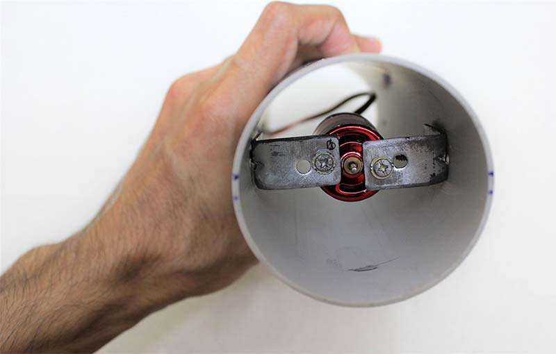
FIGURE 14. The DC motor fixed with two L clamps.
For the impeller, I chose an old DC cooling fan which was lying around my house. The diameter of the fan should be close to two inches. All the windings and armature were removed to expose the bare fan (Figure 15).
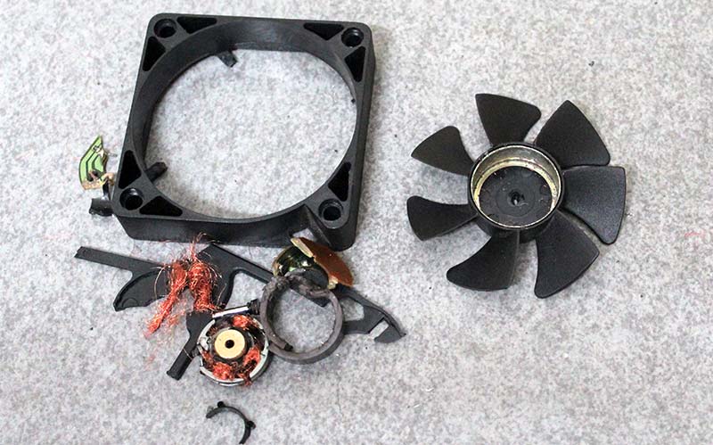
FIGURE 15. The impeller from a DC cooling fan (on the right).
Since the fan doesn’t have any setup to fix it on to the motor shaft, a separate attachment was required. The motor also had a thin shaft diameter, making it harder to find a readily available shaft coupler attachment. This called for an unconventional method for fixing the impeller.
I’ve often noticed that the toy fans in hobby kits have a perfect hole setup for attaching on to the motor. Hence, I thought of using that with the impeller. First, the blades were cut off to leave behind the center portion which carries the hole (Figure 16).
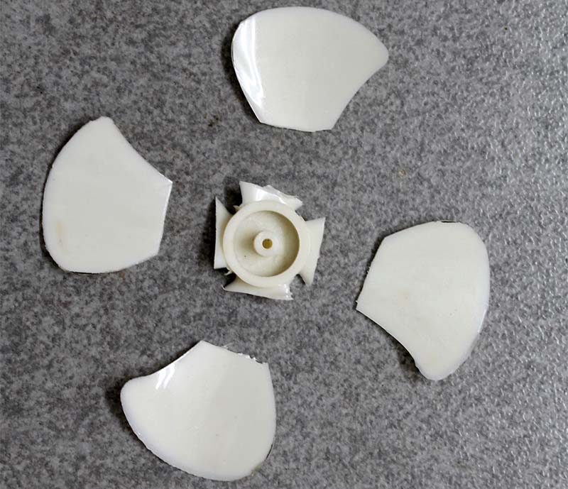
FIGURE 16. The center portion cut from a toy fan.
This is then fixed on to the center of the impeller using epoxy putty. Once the epoxy is cured, attach it on the motor shaft using super glue (Figure 17).
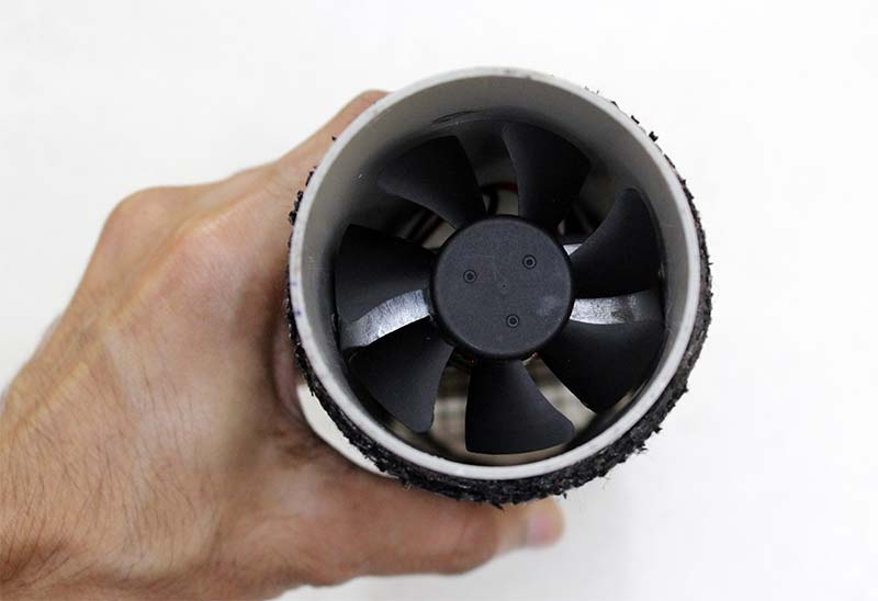
FIGURE 17. The impeller fixed on to the motor shaft.
A metal dust mesh placed between the main body and front head section prevents the dust from impacting the impeller, thus containing the dust within the front head section (Figure 18).
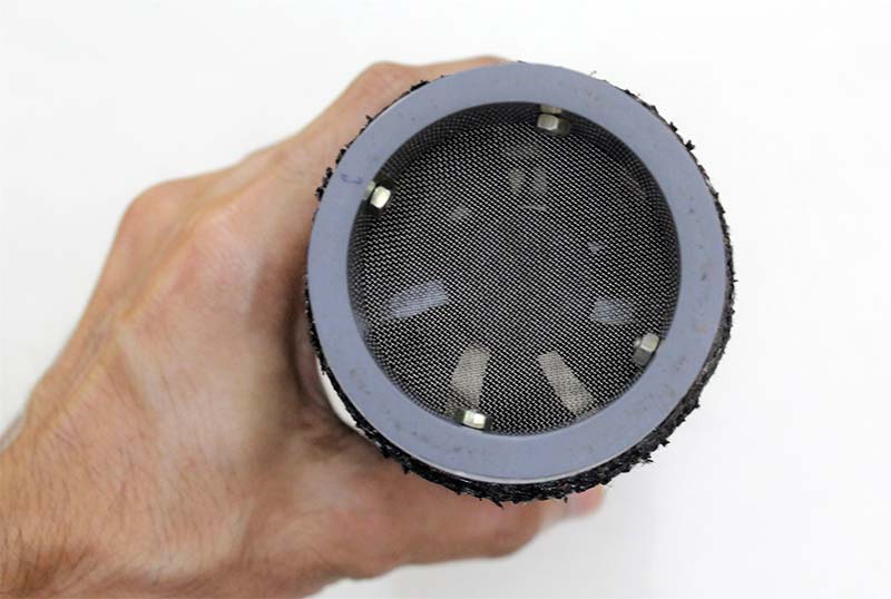
FIGURE 18. The dust mesh at the front of the impeller.
It’s made from a 1.5 inch PVC end cap. Its closed end is cut open to form a ring-like structure. Then, a fine metal mesh (from a tea strainer) is folded over the end and fixed with bolts along the sides (Figure 19 and Figure 20).
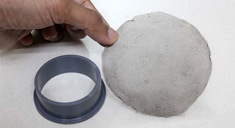
FIGURE 19. The 1.5 inch PVC end cap and the metal mesh.
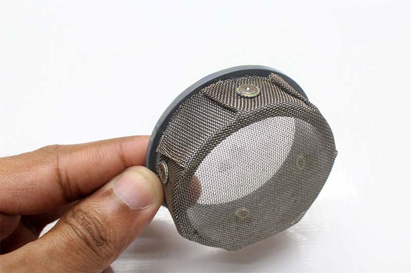
FIGURE 20. The finished dust mesh.
This forms a simple and effective dust mesh for the vacuum cleaner. It’s then inserted (mesh side up) on to the front side of the main body section (Figure 18).
The Casing for the Circuit Components
The circuit components are securely fixed inside a rectangular casing made from a 1.25 inch PVC pipe. For acquiring the shape, a rectangular die is made from cutting a plywood section (Figure 21).
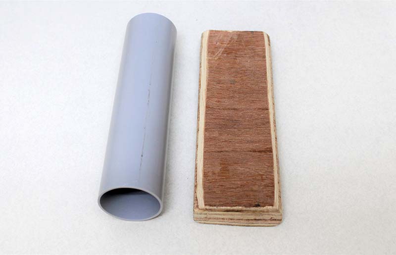
FIGURE 21. The 1.25 inch PVC pipe and wooden die.
It has a width of 5.5 cm, length of 16 cm, and a thickness of 2 cm.
Once the PVC pipe is thoroughly heated, the plywood die is slowly inserted from one side until it reaches the other end. Once the PVC is cooled, it tightens up the die, making it difficult to be pulled out.
The casing was again slightly heated to loosen up the friction, making it easy to pull out the die from the casing. Further, four slits were made on the corners. These were then folded on top of each other to fully close that end. This completes the custom PVC casing for enclosing the circuit components (Figure 22).
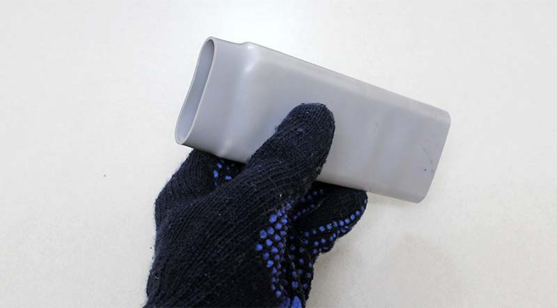
FIGURE 22. The PVC casing made from inserting the wooden die.
On the other open end of the casing, a DPDT switch, a DC socket, and a micro USB port are fixed. For this, I used the previous heating and folding technique to make a C shaped PVC section. This section should act like a lid where the two legs should go inside the casing.
Using a soldering iron, cut-outs were made on this section for the sockets and the switch. Once they are inserted, it’s fixed using epoxy putty (Figure 23). Another cut-out for the second DPDT switch is also made on the casing.
FIGURE 23. The top lid section consisting of the DC socket, micro USB port, and DPDT switch.
Things are almost done now. The fiberglass sheet with the components attached can now be inserted into the casing (Figure 24).
FIGURE 24. The circuit components inserted into the PVC casing.
The wires extending from it can be connected to the lid section consisting of the sockets and switch as shown in the wiring diagram. This setup is now inserted into the main body section and fixed in place using a bolt. The second DPDT switch on the main body section is also now properly soldered and fixed.
Conclusion
The vacuum cleaner is all done and ready to use now!
Making this project was truly a great experience and I was able to work on both the electronics and designing aspects of building a prototype. Since it’s very compact, you don’t need a particular place for storing it.
It’s very useful in cleaning laptops, air conditioners, and all sorts of stuff. The only thing it can’t do is deep clean sofas and cushions.
For everything else, you can count on it. I hope you enjoy the build. NV
Parts List
PVC Pipe Fittings
1.5-0.5 inch PVC reducer x1
2 inch coupler x1
0.5 inch PVC pipe — around 30 cm length
2 inch PVC pipe — 21 cm length
1.25 inch PVC pipe — 16 cm length
1.5 inch PVC end cap x1
Electronic Components
18650 Li-Ion cells x2
1S 18650 BMS (battery management system) module x1
Lithium battery charging board x1
Constant current/constant voltage (CC/CV) buck converter x1
DC motor x1
DC cooling fan (diameter close to two inches) x1
Switches & Sockets
Female DC power socket x1
Female micro USB port x1
6A rated DPDT switch with three positions (ON-OFF-ON) x1
6A rated DPDT switch with two positions (ON-ON) x1
Other Main Parts
Epoxy putty — 100g pack
Synthetic rubber adhesive — around 300 ml
Zip ties — 10 nos
Jute cloth piece — 50 cm x 50 cm
Fiberglass sheet — a small piece
Velcro strips — a small piece
A tea strainer for metal mesh
A plywood piece — width 5.5 cm, length 16 cm, thickness 2 cm
DC motor toy fan x1
One inch L clamps x2