Knowing your pet’s location is invaluable. With modern technology, there are commercial solutions giving accurate GPS location for days on end. However, these options are costly. So, as a useful and educational project, I built my own tracker using a simple radio beacon.
Sitting on my porch, I watched the neighborhood cat roll around in the gutter, then stroll off down the sidewalk. I wondered where he might have gone. This project is an attempt to answer that question and learn about radios along the way.
Tracking animals is not a new idea. If you do some research about electronic locators for small animals, you’ll quickly be presented with options costing upwards of $100 that use GPS to locate the collar and a cellular connection to report back the device’s location. If you look for cheaper options, most use Bluetooth and simply notify you when the device is out of range. None of these options were what I was looking for. So, in the spirit of amateur radio, I set out to do it myself.
The scientific community has driven the development of animal tracking technology since the ability to follow movements of animal species can reveal very useful information about their behavior. They often use a simple transmitter that produces a carrier wave on the desired frequency in short bursts.
To utilize this, a person with a radio receiver tuned to the same frequency uses a directional antenna such as a Yagi-Uda antenna to determine the area where the signal is coming from. This direction is referred to as the angle of arrival. By marking this bearing on a map, moving to another location and repeating, the approximate location of the transmitter can be determined as where the two bearings intersect.
This activity is called radio direction finding. Amateur radio operators have made a sport out of using directional antennae and radios to locate a hidden transmitter in all sorts of terrain. This skill is used by professionals to eliminate interference and find persons during search and rescue operations.
Radio direction finding techniques are used by multiple groups such as emergency aid responders, avalanche rescue, and military reconnaissance. Many civil aircraft have radio beacons to help locate them in the event of a crash. Avalanche transceivers help locate people who have been buried by snow.
To build my own radio direction finding system, I decided to use a generic 433 MHz radio transmitter module commonly utilized for Arduino projects. I chose this because they’re inexpensive, simple to use, and only require power and a signal to operate.
I made a prototype using an ATtiny85 that would power a pin on the ATtiny85 for a half second every second.
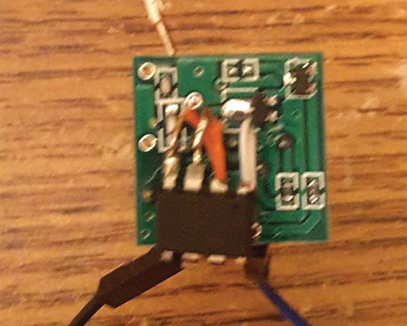
FIGURE 1. First prototype using an ATtiny85.
This pin was connected to the data pin of the board and, in turn, caused the transmitter to turn on and off with the pin. In theory, this would use less power than transmitting constantly.
However, after connecting it to an ammeter, I realized that it is more power-efficient to route three volts directly to the data pin, and have it transmit continuously since the ATtiny85 was drawing more power than it saved. With continuous transmission, a name brand coin cell battery would power it for 48 hours.
I assembled another version without the ATtiny85 by attaching the board to a CR2032 coin cell battery holder using hot glue. I routed the 3V power to the VCC and Data pins on the board. I also soldered a thin piece of copper wire to the ANT port to act as an antenna. This small copper wire was wrapped around the battery holder and was held in place with hot glue.
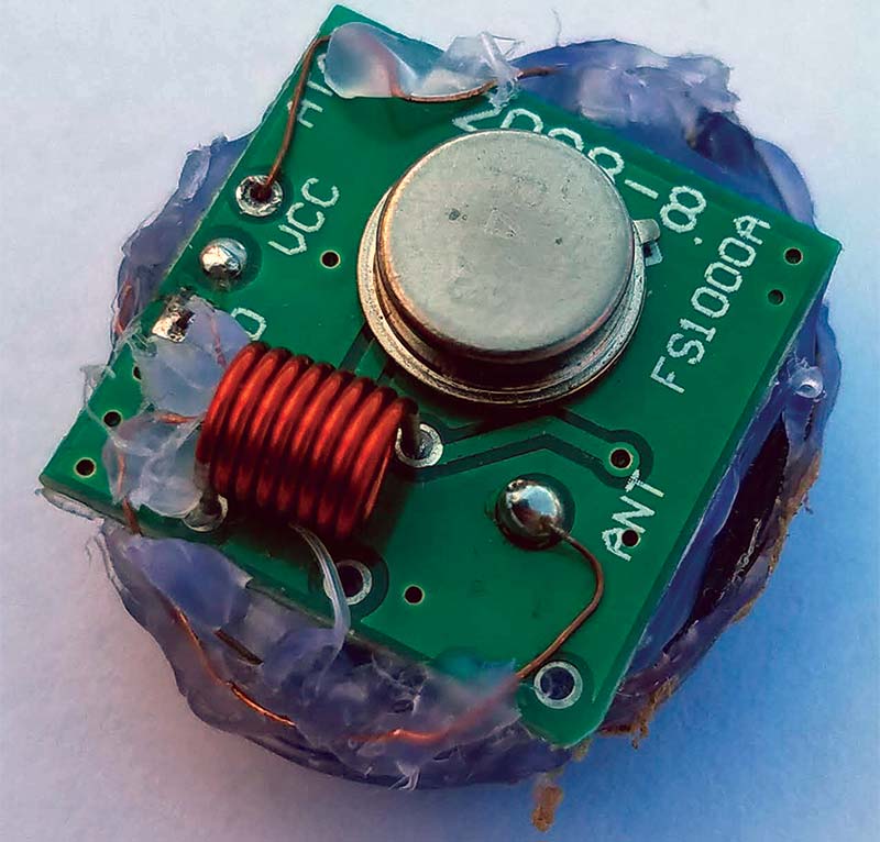
FIGURE 2. Second prototype with battery holder and wrapped antenna.
To receive the signal, any radio receiver capable of tuning to 433 MHz would work, although higher sensitivity is better. I used a Baofeng UV-5R handheld radio transceiver. In combination with the radio, you’ll need a directional antenna.
A directional antenna is built so that it has significantly more gain in one direction relative to the antenna. Most radio direction finding applications use Yagi-Uda antennas. I built a Yagi-Uda antenna for 433 MHz with six elements using copper wire and PVC pipe.
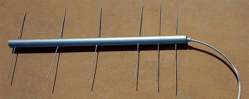
FIGURE 3. Handmade six-element Yagi-Uda antenna.
After some tests, I realized that there were two issues with the system: The antenna was not directional enough; and the transmitter’s signal was not strong enough.
To fix these issues, I made another transmitter; this one with the antenna not wrapped around the battery holder but instead sticking straight off the board. I also added a length of wire to the ground pin acting as a dipole. For this antenna, I calculated 1/4 of the radio wavelength at 433 MHz which is 17 centimeters.
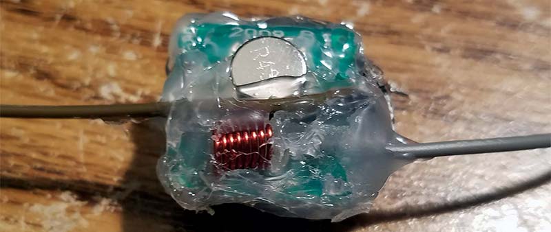
FIGURE 4. Most recent revision with dipole antenna.
The Yagi-Uda antenna’s issue was most likely a poor electrical connection between the coaxial cable and driven element. For the antenna, I tried using an Arrow II satellite antenna which is a dual band Yagi meant for sending and receiving radio signals to and from amateur radio satellites. It worked very well in conjunction with a Baofeng UV-5R.
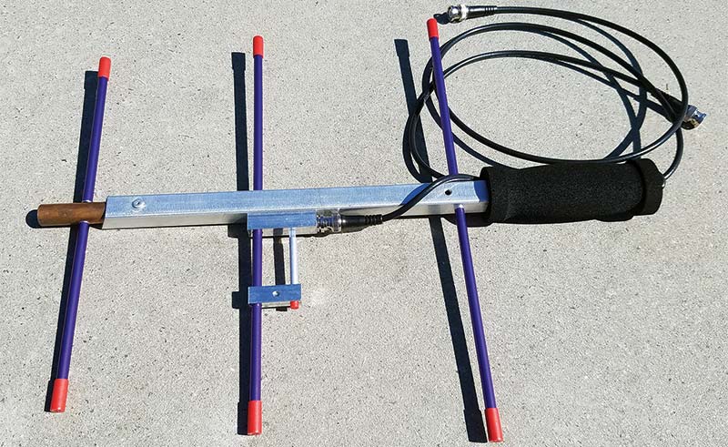
FIGURE 5. Bottom half of Arrow II satellite antenna for tracking.
With this system, I was able to find the angle of arrival and get a clear signal from 1/2 mile away in a dense urban neighborhood. I used the cell phone application, SigTrax to assist with plotting the bearings, but this could be accomplished with a map and compass.
SigTrax is an application available for iOS and Android that utilizes the cellular phone’s GPS and inputs from the user to assist in triangulating radio signals. This saves a lot of time and effort when faced with plotting bearings on a map manually.
This method works well in relatively open areas. However, in an urban neighborhood with back-to-back houses, the signal reflects off these buildings and arrives at a different location than it originated from. So, instead of plotting bearings, I simply followed the direction at which the signal is strongest and eventually arrived at the source. This is because the streets act as a sort of tunnel for the radio waves.
After practicing with the tracker in a stationary position, I put a snug canvas cover on it and attached it to a collar to put on my cat. After giving the cat some treats and a pat on the head, I watched him wander away.
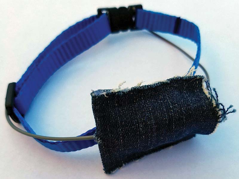
FIGURE 6. Transmitter in canvas case attached to cat collar.
Throughout the day (using my antenna and radio), I found him laying under a car, standing on a fence, and socializing with some of the neighbor’s dogs.
Building a radio tracker for your favorite pet can be a very interesting and educational use of electronics.
For less than the cost of a pack of gum, you have a reusable radio beacon light enough to be carried by most animals. The components used in the project can also be repurposed for other projects. NV
Parts List
- 433 MHz Transmitter Module
- Hookup Wire
- CR2032 Coin Cell Battery Holder
- Handheld Radio capable of tuning to 433 MHz (Baofeng UV-5R)
- Directional Antenna for Radio
Resources
SigTrax App
www.amcept.com/sigtrax
Radio
https://baofengtech.com/uv-5r
Antenna
www.arrowantennas.com/arrowii/146-437.html