Arduino Unos and Megas are normally powered by five volts through their USB connectors or by connecting 7-12 volts to the power jacks or Vin header pins. However, there is another way.
An external power supply (+5 volts ±0.25V) can be connected to the header pin marked “5V.” This is sometimes done when an Arduino is part of a larger system where there are other components that also require five volt power. Figure 1 shows a typical example on the right where an external five volt source is used to handle a servo, an LCD, and other types of five volt devices along with the Arduino.
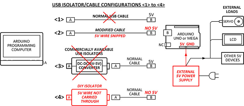
FIGURE 1. A modified cable or DIY isolator eliminates conflict between the five volts in the programming USB cable and an external 5V power supply.
The various cable configurations <1> to <4> will be discussed shortly.
THE BIG DEBATE
Over the years, many knowledgeable people have debated the issue of connecting to the Arduino 5V header pin, but their opinions are mixed. Some say yes, some say no, some say maybe.
The debate centers around many factors including using unregulated supplies, the possible effects of reverse driving the NCP1117 on-board regulator, the characteristics of the MOSFET and its body diode, conflicts with the USB +5V line, functioning of the USB PTC fuse, bypassing the auto-sensing/voltage protection circuitry, and finally, the possibility of bricking the board by not taking into account one or more of the possible pitfalls listed above. So many things to consider!!!
A QUICK AND EASY SOLUTION
Fortunately, there is hope! I have built at least a dozen fairly complicated Arduino projects using external power supplies and have never had a problem with two important caveats. I have always used well-regulated supplies (5.0 volts ±0.25V) and custom modified USB cables to program the Unos and Megas.
Figure 2 illustrates the modified USB cables I made for the projects.
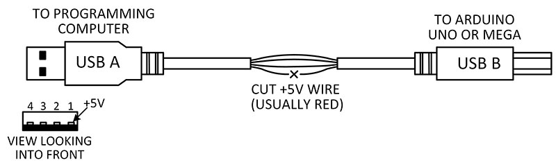
FIGURE 2. A modified USB cable is easy to make so you can program Arduinos that are part of a larger system.
Other users have also opted to similarly transform normal USB A/B cables into “Arduino-dedicated USB programming cables” by snipping the red +5V wire. I identify mine with red electrical tape.
WHAT IF YOU DON’T USE A MODIFIED USB CABLE?
SITUATION #1:
Arduino Setup: Please refer to <1> and <2> in Figure 1 again.
Action: You connect a normal USB cable (<1>) from your computer to the Arduino, BUT you don’t turn on the external supply for several minutes.
Result: Your computer’s USB port tries to supply current to everything — Arduino, servos, LCD, etc. If the load is over 500 mA, it either blows the Arduino’s USB fuse or the computer shuts down its port. Hopefully, nothing is damaged.
Solutions: Either snip the +5V red wire in the USB cable (<2>) OR use my DIY isolator (<4>).
SITUATION #2:
Arduino Setup: Same as the previous situation, but ...
Action 1: This time, you turn on the external supply first and there doesn’t appear to be any problems.
Action 2: You connect a normal USB cable (<1>) from your computer to the Arduino.
Result: Unbeknownst to you, the +5V in the USB cable and the external supply are fighting each other. Depending on which source is higher or lower in voltage, the USB cable can become overloaded, with the same result as in Situation #1.
Solutions: Either snip the +5V wire in the USB cable (<2>) OR use my DIY isolator (<4>).
WHY NOT JUST BUY ONE OF THE “USB ISOLATORS” SOLD ON AMAZON?
The USB isolators sold on Amazon (as seen in Figure 3) are designed to reduce noise on the USB data and power lines when different types of equipment are hooked together.
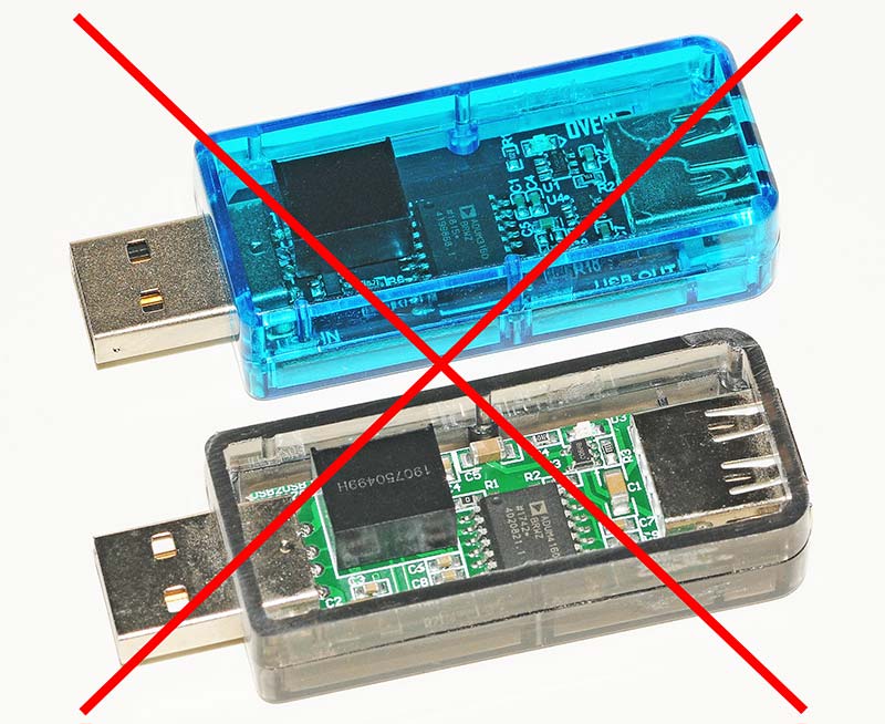
FIGURE 3. Commercially available USB isolators are not recommended because they contain a DC-DC converter that can become overloaded.
However, I don’t recommend using them if you power your Arduino with an external power supply because they contain a small DC-to-DC converter that continuously sends five volts to the Arduino. Take a look at the situation below.
SITUATION #3:
Arduino Setup: Please refer to <3> in Figure 1.
Action: You connect a commercial USB isolator and a normal cable but haven’t turned on the external supply yet.
Result: As soon as you connect the USB cable, your computer’s USB port and the isolator’s DC-DC converter will try to supply current to everything — Arduino, servos, LCD, etc.
Overload: If the external devices require a hefty current like 500 mA or more, the DC-DC converter will lower its output but will still supply a large amount of current. There’s a chance that it could overheat and fail. They are only rated to supply 200 mA.
Proof: I ran a series of tests on several commercial units (shown in Figure 3) under overload conditions. The little black DC-DC modules get very hot when they have to supply 400 mA. Because of that, I would not recommend them for this specific application. However, as a general USB signal isolator, they work fine, as evidenced by user comments on Amazon.
Solutions: Either snip the +5V red wire in the USB cable (<2>) OR use my DIY isolator (<4>).
DIY ISOLATOR ON A PCB
The other day, I got a wild hair and said there must be a better way than slicing open a cable. That’s when it occurred to me that a simple isolator (Figure 1, <4>) could be built into a little plastic Serpac box.
Figure 4 shows a completed isolator in a box that only involves two connectors and a little PCB (printed circuit board).
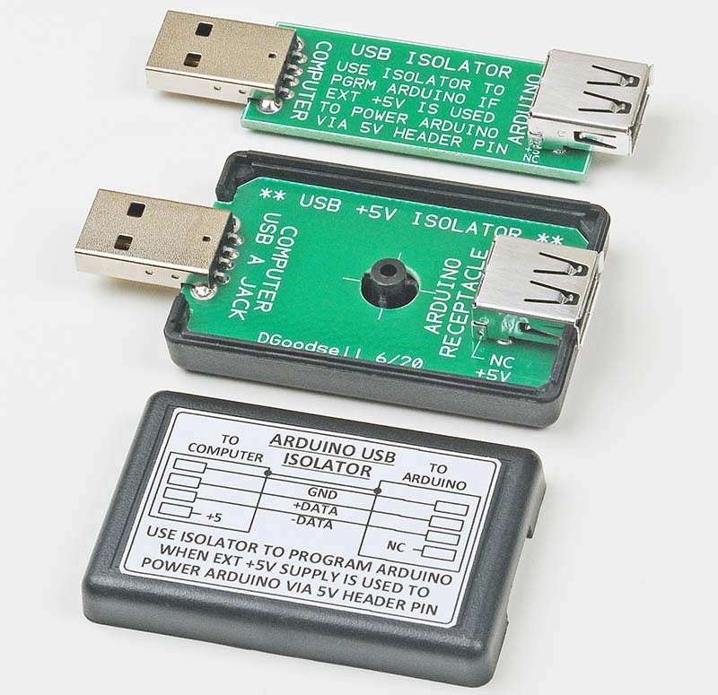
FIGURE 4. Enclosed and bare-bones DIY isolators are convenient and allow the use of normal, unmodified USB cables to program externally powered Arduinos.
Notice that only the +5 volt wire is not carried through. Pretty simple.
Or, if you want to skip the box, a bare-bones version is shown at the top of Figure 4.
Figure 5 shows the dimensions of the cutouts if a Serpac C4 box is used.
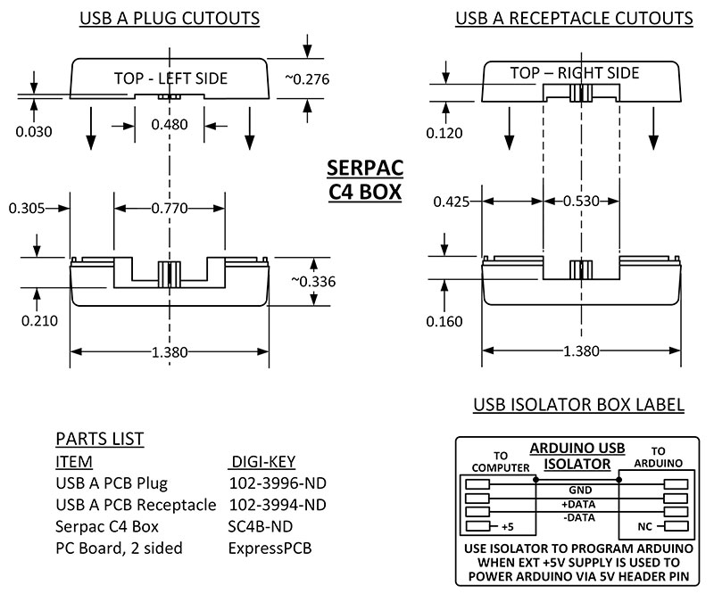
FIGURE 5. Dimensions of the cutouts in the Serpac C4 box for USB A plugs and receptacles. Plus, the Parts List.
You may need to get out your needle files and use the tried and true method: “file to fit.”
Gerber and ExpressPCB files for the boards are available in the article downloads.
END THOUGHTS
This is a very simple project, but it sure makes programming easier than searching for the special red cables every time. BTW, I would welcome a fresh debate about the pros and cons of using the “5V” header pin in case I missed something. Please enter your opinions at the end of this article. Thanks for your time. NV
Please feel free to contact me at [email protected] for comments, corrections, or any private communications.
Downloads
What’s in the zip?
ExpressPCB PC Layout File
Note: ExpressPCB layout software must be loaded to read this file.
Gerber Files for ExpressPCB PC Boards