A dummy load is a resistor used to load any radio frequency generator/amplifier to simulate an antenna for testing purposes. It’s used to allow full power output while testing or experimenting without radiating a radio frequency signal. As the radio frequency power is converted to heat, interference is avoided.
Amateur radio operators (hams) or anyone who builds or experiments with radio transmitters should have and use a good dummy load.
I noticed 100 watt 50 ohm resistors on eBay listed at five for $6.50 or one for $1.99. As the resistors were designed to be used as RF loads, I decided to make a good dummy load using only tools that most homes have. The 100 watt resistor and SO-239 connector are shown in Figure 1.
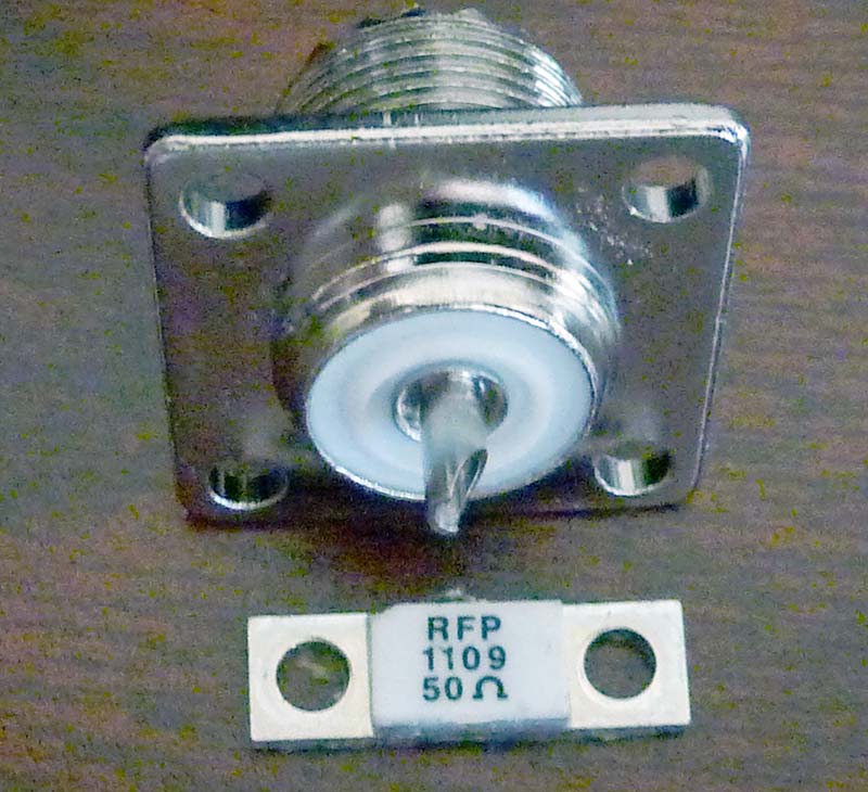
FIGURE 1. A 100 watt resistor and SO-239.
I decided to mount the resistor to the flange of the SO-239 connector. This would make a very small current loop with little radiation, eliminating the need for shielding. Any RF current flowing around a loop radiates, but as the area enclosed by the loop goes to zero, the radiation also goes to zero. The smaller the current loop, the poorer it is as an antenna.
To mount the load on an SO-239, I cut away a small portion of the connector’s back using a hack saw, so as to allow the 50 ohm resistor mounting plate to fit entirely on the SO-239. Refer to Figure 2 for the modified SO-239. Use a file to remove any burs and obtain a flat mounting surface.
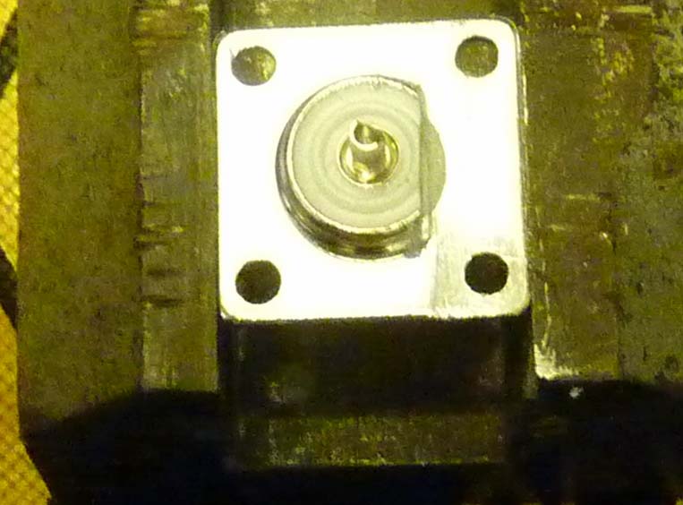
FIGURE 2. Modified SO-239.
Next, I drilled holes in the SO-239 flange to match those of the 50 ohm resistor and mounted it using some heatsink compound. I utilized 4-40 screws to avoid the nuts putting pressure on the resistor’s ceramic body. I then used a small piece of copper foil to connect the resistor to the SO-239’s center pin. If you don’t have foil, use some solder wick or stripped braid from coax shield. The other lead of the resistor is its mounting base plate. The dummy load is shown in Figure 3.
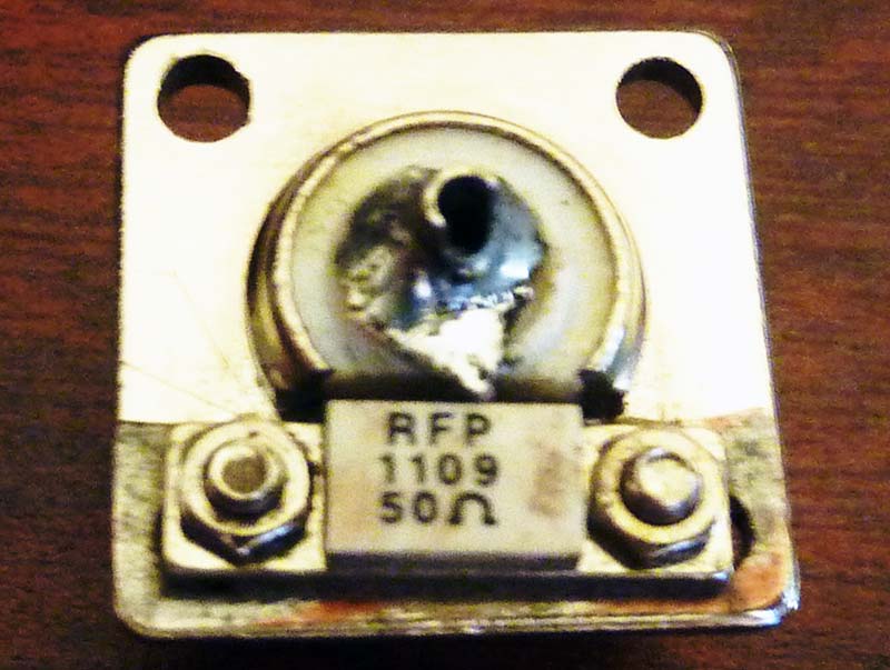
FIGURE 3. The dummy load.
I checked the VSWR with an antenna analyzer and it was 1:1 up to 175 MHz (my testing limit). The resistor is rated for use up to 3 GHz. If you’re going to use it above 450 MHz, I would test the one you build to see that it stays at 50 ohms.
Without a heatsink, this dummy load will dissipate five watts with the heat going into the Pl-259 mating connector and its coax. For a low duty cycle, it can take much higher power.
The challenge then becomes how to dissipate 50 watts CW for a couple of minutes; 50 watts being the maximum 100% duty CW output power of most 100 watt transceivers. This required a heatsink that anyone could add using only hand tools.
I chose a length of 1/2 inch aluminum angle I had laying around. I cut it about seven inches long. I filed away a partial circle so I could get more contact area between the angle iron and the S0-239.
On the first try, I filed too much and drilled the mounting screws too close to the bend in the angle. It didn’t lay flat to the S0-239 connection. I then made sure the mounting holes in the angle were located so that it pulled it flat to the SO-239 flange when the screws are tightened.
I offset the mounting point two inches to five inches to allow extra dissipation using a glass of ice water as part of the heatsink. I used some heatsink compound mounted on the angle with 6-32 screws.
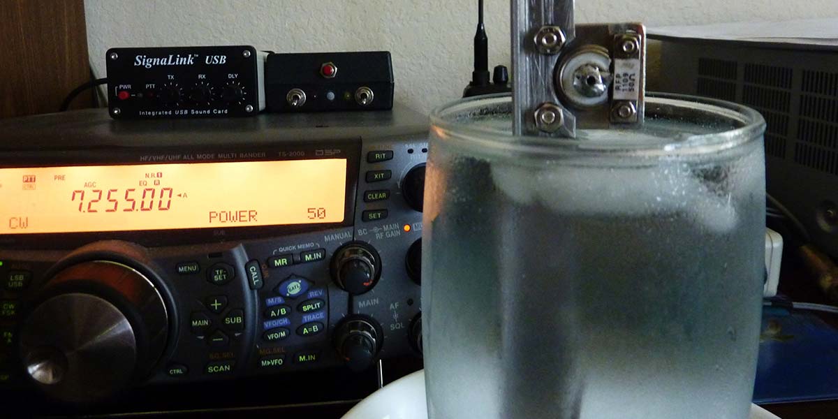
While dissipating 50 watts for two minutes with ice water, the 50 ohm resistor’s top surface is under 212°F; refer to Figure 4. The heatsink in ice water with a dry load dissipated 50 watts.
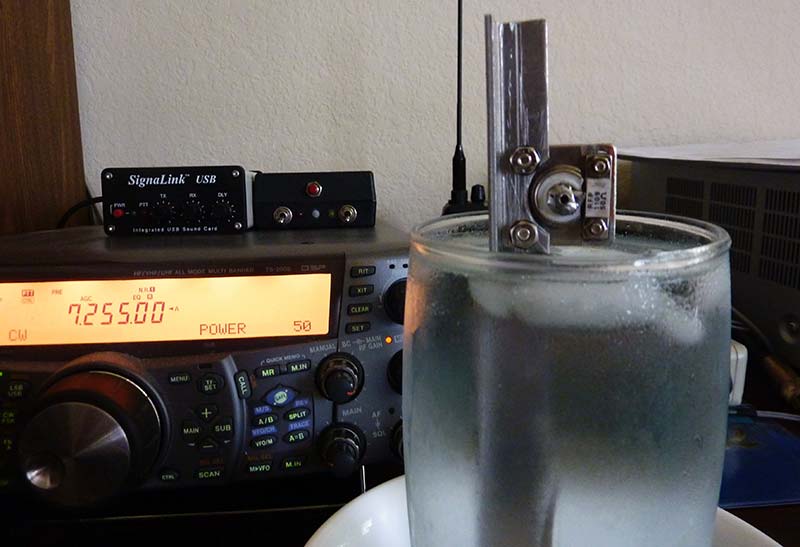
FIGURE 4. The heatsink in ice water with a dry load dissipating 50 watts.
I didn’t give any exact measurements for drilling and filing as none are needed. It’s easy enough to eye-ball.
If you have four buddies to split up a package of five resistors and a length of aluminum angle, this load can be made for less than $3. If you only make one, it will still cost less than $5. Can’t beat that! NV
Parts List
Each device requires the following:
- 100W 50 ohm resistor
- SO-239 connector
- 6” of 1/2” aluminum angle
- One tube heatsink compound