What is a Ribbon Controller?
The last few years have seen a massive resurgence in the popularity and availability of voltage-controlled synthesizers. These synthesizers — whether modular, semi-modular, or stand-alone — are all characterized by voltage control of their various parameters. These voltages are known as control voltages; henceforth, abbreviated to CVs.
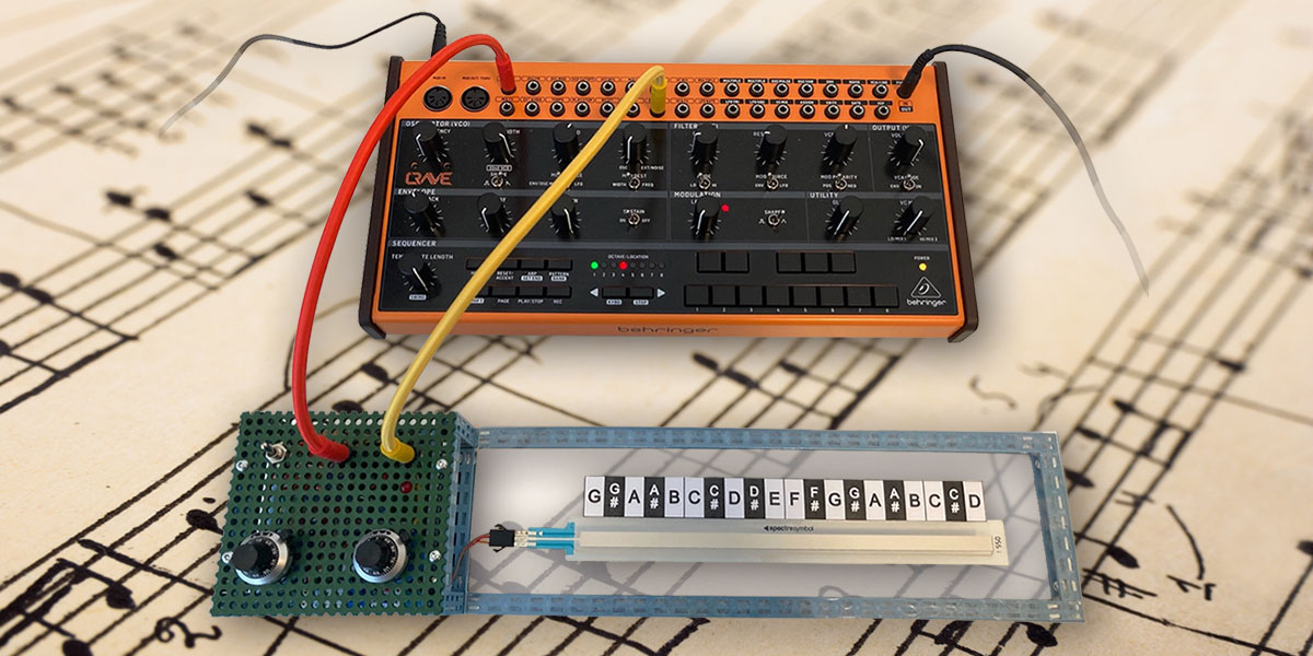
The ribbon controller we’ll construct in this article is shown in Figure 1 connected to my Behringer Crave analog synthesizer.
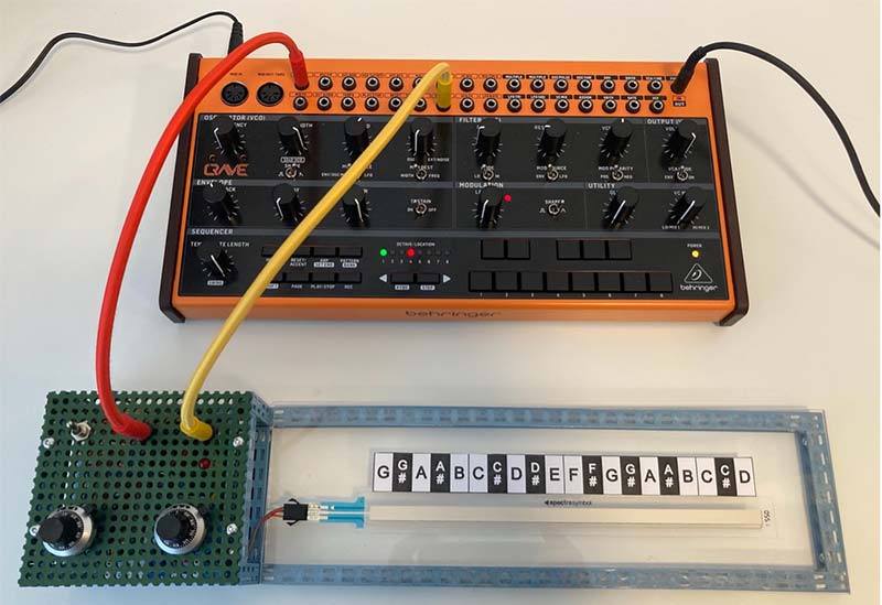
FIGURE 1. A 200 mm SoftPot ribbon controller set up for pitch use and connected to a Behringer Crave analog synthesizer. The red cable is the pitch CV and the yellow cable is the gate. The chassis is constructed using the Totem Maker system with a piece of acrylic providing a smooth platform for the SoftPot.
Ribbon controllers for voltage-controlled synthesizers can take many forms, but they all have similar requirements:
- A ribbon that you touch (a Spectra Symbol SoftPot in this case).
- An output CV that is proportional to where you touch the ribbon (red cable). This is a continuous voltage range, rather than the quantized stepped voltages output by keyboards.
- A gate CV that is high when the ribbon is touched and low when it’s not (yellow cable).
- Potentiometers to set the start and end voltages for the ribbon (the two multi-turn knobs on the panel).
- An LED to indicate when the gate triggers. This is essential for setting it up.
Ribbon controllers are fantastically fun, useful, and versatile devices. Obviously, you can use them to control the pitch of an oscillator as in Figure 1, but you can also use them to control any of the myriad voltage-controlled modulation opportunities provided by the typical voltage-controlled synth.
When you use a ribbon controller to control pitch — with the appropriate voicing — you can easily get Theremin or Ondes Martenot like continuous pitch effects. In fact, a ribbon controller generating pitch CV into a sine wave oscillator is pretty much functionally and sonically equivalent to the Electro-Theremin (invented by Paul Tanner and Bob Whitsell) that was used on the famous “Good Vibrations” track by the Beach Boys. See the Resources for links to information about these instruments.
When used for pitch control, ribbon controllers are very amenable to vibrato (fluctuations in frequency), which you achieve just by wiggling your finger back and forth. This makes them expressive instruments that are a great addition to the keyboard.
Spectra Symbol SoftPots
This article describes a very simple ribbon controller that uses a Spectra Symbol SoftPot ribbon potentiometer for the ribbon. A selection of standard SoftPots is shown in Figure 2.

FIGURE 2. A selection of Spectra Symbol SoftPots. These happen to have a female connector, but versions with Crimpflex solder tabs are more widely available.
If you can afford it, Spectra Symbol will manufacture SoftPots to order in almost any size and shape you can think of. The circuit works with any of the SoftPots, so you can easily create ribbon controllers in different lengths and geometries.
Working with SoftPots
It’s easy to think of a SoftPot as just another potentiometer. However, they have some very significant differences that you need to carefully consider when designing with them:
- A 10K SoftPot has a resistance at the wiper between 0 and 10K when pressed, depending on where you press it. This goes to infinity (open circuit) when it’s not pressed. This is very different to a potentiometer which is never open circuit unless you burn it out.
- The SoftPot is a thin film device that can dissipate a maximum of 1W of power. At 5V, this is only 200 mA. Believe me, they are incredibly easy to burn out if you’re not paying attention. Connect it to a battery and mix up the wiper with one of the other two terminals and poof! You release the magic blue smoke. The best strategy is to never draw a current from the SoftPot wiper. We’ll see how to arrange this shortly.
- Because SoftPots can’t handle much current, they should never be used as a variable resistor. Their correct usage is as a potentiometer into a high impedance input.
- They have very fine pins and are constructed of plastic that is quite easy to melt.
The last point bears closer examination. The SoftPots readily available from SparkFun and Cool Components are terminated by three Crimpflex solder tabs. If you examine these carefully, you’ll see that they are pins stapled to the plastic substrate of the SoftPot so that they are in contact with the thin resistive films. These connections are fragile, and it’s easy to damage them mechanically or with heat. Because the SoftPot is plastic, again, it melts very easily (and expensively).
It’s possible to solder to the SoftPot Crimpflex solder tabs, but there is a risk of damaging the expensive component. I confess that I have never tried to solder them, but apparently, if you have nerves of steel and can arrange some sort of heatsink on each pin as you solder (e.g., grip the pin in snipe nose pliers), it’s possible to do it.
Rather than risk damaging the SoftPot, it’s best to use a socket. Crimpflex tabs fit securely in a solderless breadboard, but unfortunately, they’re too thin to work with standard DuPont female headers. I have found two types of connectors that work:
- JST-SM Three-Way Female Headers. Even though this type of connector is associated with thicker wires and higher currents, it holds SoftPot tabs very securely and works well. JST-SM connectors are often used with LED lighting and are easy to get hold of. You can buy kits to make up your own (which is what I do), but take my advice and make sure you get the correct crimping tool if you want to try this!
- The Turned Pin SIL (Single In-Line) IC Socket. This comes in a strip, and you break off as many sockets as you need. These also hold the fine SoftPot tabs very securely, but they are a bit fiddlier than the JST-SM connectors because you need to either solder directly to the SIL pins or mount the socket on a piece of stripboard.
Whichever type of connector you choose, be sure to do all soldering to the connector before plugging in the SoftPot. Also make sure you arrange a strain relief for the connector.
Using a SoftPot as a Ribbon Controller
The idea is very simple: All we need to do is set a start voltage and an end voltage across the SoftPot and take the CV off its wiper. However, as we’ll see, it gets a bit more complex in practice.
A naive approach is to use a couple of potentiometers to set the start and end voltages as shown in the circuit simulation in Figure 3.
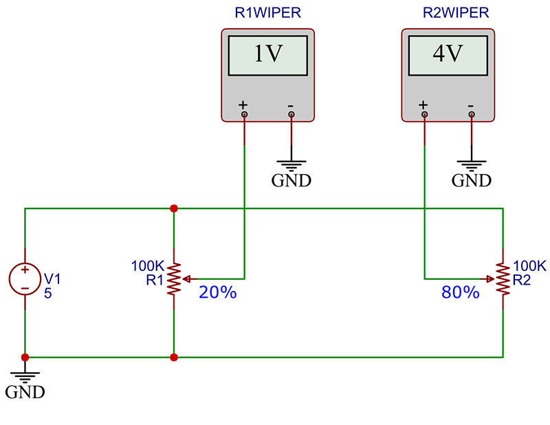
FIGURE 3. Two potentiometers R1 and R2 allow us to set start voltages at their wipers. Simulation is in EasyEDA.
I used EasyEDA for this simulation (see Resources). In this circuit, the supply voltage, V1, is set to 5V; R1 is a 100K pot set to 20% of its range; and R2 is a 100K pot set to 80% of its range.
The voltage on the wiper of R1 is 20% of 5V = 1V, and the voltage on the wiper of R2 is 80% of 5V = 4V. The potentiometers act as simple voltage dividers as expected. So far, so good! We have two voltages that we can use for the start and end voltages for the SoftPot. Or, can we …
Consider the circuit simulation in Figure 4.
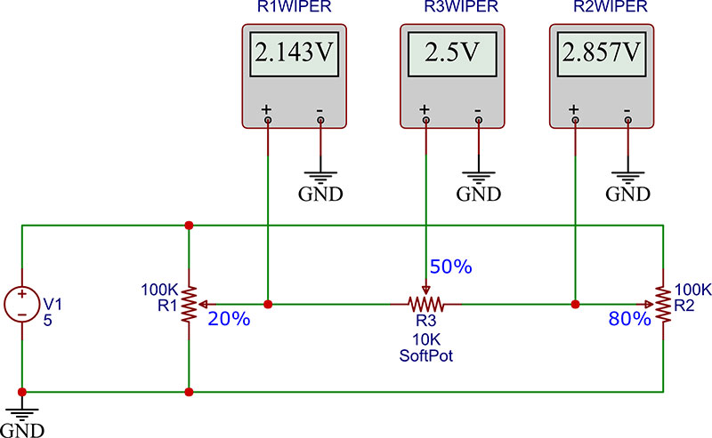
FIGURE 4. Addition of another potentiometer (a 10K SoftPot) connecting R1 and R2 wipers perturbs their wiper voltages. Simulation is in EasyEDA.
We have added a 10K SoftPot, R3, connecting the wipers of R1 and R2. This simple addition complicates things very considerably. R1 wiper is now connected via the 10K SoftPot to R2 wiper which is at a higher voltage. This pulls the R1 wiper voltage up a bit. Similarly, R2 wiper is connected via a 10K SoftPot to R1 wiper which is at a lower voltage; this pulls the R2 wiper voltage down a bit.
Neither voltage is proportional to the potentiometer setting, and much worse, the wiper voltages modify each other, so a change to R1 affects R2 wiper voltage and vice-versa. The situation gets even more complex if there’s a significant load on the SoftPot wiper because the extra current flow also has an effect.
R1, R2, and R3 in Figure 4 form a surprisingly complex resistor network. We know that for a given wiper setting, a potentiometer is equivalent to two resistors in series with the wiper voltage at their junction.
Given this, we can draw an equivalent resistor network for Figure 4, plus a load resistor for completeness as shown in Figure 5.
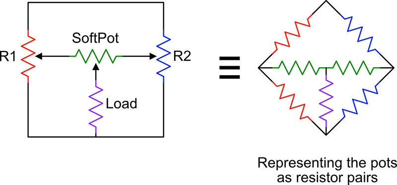
FIGURE 5. Three potentiometers make a surprisingly complex resistor network.
This is complex because there are no pairs of resistors in series and no pairs of resistors in parallel even though at first glance it looks as though there might be. See if you can convince yourself of this given the following definitions:
- For resistors in series, the current is the same through all of them.
- For resistors in parallel, the current going into the parallel resistors is equal to the current going out.
There is nowhere in the circuit where these two conditions are met.
To calculate total resistance between any pair of nodes in the network, we need to apply a ΔY (Delta Wye) transformation to simplify it so that we have only series and parallel resistors. I describe this in some detail in the sidebar if you’re interested.
This simple approach — using potentiometers to set the start and end voltages for the SoftPot — is completely inadequate. The result is that everything interacts with everything else, and it becomes very difficult to set the start and end voltages to the desired values.
Delta Wye (ΔY) Transformation
A three-resistor cycle in a resistor network forms a triangle or delta shape. This delta shape may be substituted with an equivalent network comprising three resistors arranged in a Y shape. This is the Delta Wye (ΔY) transformation (see Resources), and it’s an essential tool for dealing with complex resistor networks.
To successfully apply ΔY, you must be very consistent in how you label the resistors and junctions in the circuit. Otherwise, it’s all too easy to get into a mess! I always like to think of resistor networks as graphs made of nodes and edges (if you don’t know Graph Theory, don’t worry, you don’t need to). The nodes are circuit junctions and the edges are resistors between junctions. There are no wires; only junctions and resistors. This gives you a key to naming all the parts of the problem in a consistent way:
1) Nodes (junctions) are labelled alphabetically A, B, C, etc., in any order.
2) Edges (resistors) are labelled RAB, RAC, etc., where RAB is the resistor between nodes A and B and so on. The nodes should be listed alphabetically in the resistor names, so RAB is okay, but RBA would be wrong.
3) The total resistance between any two nodes X, Y can be referred to as RXY.
4) If n resistors are in parallel between two nodes X and Y, then these resistors are named RXY1, RXY2 … RXYn.
5) The voltage across any two nodes X and Y is named VXY. Unlike resistors, voltages are bipolar, so VXY = -VYX. In terms of polarity, imagine placing a positive voltmeter probe on node X and the negative probe on node Y.
Because the network connections are encoded in the resistor names, it’s possible to completely reconstruct a resistor network directly from a list of all the resistors. Also, there are natural names for the total resistance and voltage across any two nodes. This is a big improvement on more arbitrary naming schemes in which the network topology is not encoded (for example, R1, R2, etc.), that I’m surprised it’s not standard practice.
Now that we can name resistor networks consistently, let’s have a look at the actual transformation. Figure A (left) shows a delta arrangement of resistors, and Figure A (right) shows an exactly equivalent Y arrangement of resistors.
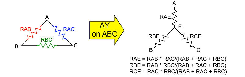
FIGURE A. The ΔY transformation. The two resistor networks are exactly equivalent.
Notice that in the Y there’s a new node, E, which is the junction of all the resistors.
The equations relating the resistors in the delta, RAB, RAC, and RBC to the new resistor, RAE, RBE, and RCE in the Y are shown beneath the Y diagram. Of course, it’s possible to derive these equations, but it’s quite a lengthy process so most people just look them up as needed.
There’s a simple pattern in the equations that make them easy to remember. Consider the equation for RAE: It comprises the two resistors joined at node A in the original delta, RAB, and RAC, multiplied together, and then divided by the sum of all the resistors in the delta.
Let’s look at applying ΔY to the circuit back in Figure 4 to see if we can calculate the voltages shown. As I mentioned, this figure is the result of a simulation in EasyEDA (see Resources), and simulation is by far the easiest way to deal with resistor networks.
Nevertheless, I think it’s instructive to understand how the magic works.
Figure B shows the transformation process.
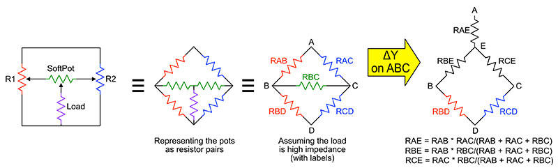
FIGURE B. Using ΔY to transform a resistor network so that it only has resistors in series and parallel.
Starting from the left, we have a simplified representation of the circuit in Figure 4 where, for completeness, we have added a load on the SoftPot. In the next circuit to the right, we expand each potentiometer by replacing it with two fixed resistors. We can do this because a potentiometer wiper divides the potentiometer resistance into two regions. You can see that the resultant network is quite complex. There are no resistors in series or parallel, and there are three deltas.
Moving to the third network in the figure, we carefully label all nodes and edges. We have now removed the load resistor for three reasons:
1) There is no load resistor in Figure 4, so we must omit it to do the calculation.
2) Synthesizer inputs can be (or can be arranged to be) quite high impedance, so “no load” can be a reasonable approximation.
3) For the purposes of this example, I want to keep it simple, and one delta is quite enough to deal with!
Applying ΔY to ABC gives us the final network AEBCD and the equations shown below it. The network AEBCD only comprises resistors in series and parallel, so we can calculate with it. The voltages in Figure 4 that we need to calculate are R1WIPER = VBD and R2WIPER = VCD. The third voltage in the figure, R3WIPER, is trivial because it’s just R1WIPER + (R2WIPER – R1WIPER)/2. Here are the actual resistor values:
RBC = 10000R (SoftPot)
RAB = 80000R, RBD = 20000R (R1 set to 20%)
RAC = 20000R, RCD = 80000R (R2 set to 80%)
It’s now possible to calculate the RED — the total resistance across nodes E and D. RBD and RBE are in series, RCD and RCE are in series, and (RBD + RBE) and (RCD + RCE) are in parallel. Therefore, using the standard equation for two resistors in parallel R = R1xR2/(R1+R2):
RED = (RBE + RBD) × (RCE + RCD)/((RBE + RBD) + (RCE + RCD)) = 20454R
We know that the voltage, VAD = 5V, so:
VED = VAD × RED/(RED + RAE) = 2.922V
Therefore, the voltages across the SoftPot, VB, and VC are:
VBD = VED × RBD/(RBD + RBE) = 2.143V = R1WIPER
VCD = VED × RCD/(RCD + RCE) = 2.857V = R2WIPER
VBD + (VCD - VBD) /2 = 2.5V = R3WIPER
This is in exact agreement with the voltages shown back in Figure 3 (bottom). I don’t think ΔY is something that you will need to use very often because, as I have already said, simulation is much easier. However, now you know how it’s done!
A Practical SoftPot Ribbon Controller
For a practical SoftPot ribbon controller, we need to eliminate the interactions between all the potentiometers so we can set the start and end voltages independently. This is easily done using an operational amplifier wired as a unity gain voltage follower (also known as a buffer). The buffer circuit is shown in Figure 6 and is one of the simplest and most useful circuits that you’ll ever come across.
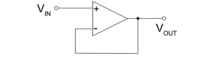
FIGURE 6. An operational amplifier configured as a unity gain voltage follower.
In Figure 6, the input impedance of the non-inverting input (+) is theoretically infinite and, in practice, is always high enough that you typically don’t have to worry about it. This means you can connect the non-inverting input to a voltage source without perturbing that source in any way. Think of it as a way of measuring the voltage source without modifying it.
In the buffer, the op-amp output is connected directly to its inverting input, which sets its gain to unity. This means the output voltage simply follows the voltage on the non-inverting input.
Op-amp outputs are low impedance, and a buffer can drive a load with no effect on its input. This is precisely what we need to isolate the voltages at the potentiometer and SoftPot wipers. All we need to do is put a buffer on the wiper of each potentiometer.
The circuit for the SoftPot ribbon controller is shown in Figure 7.
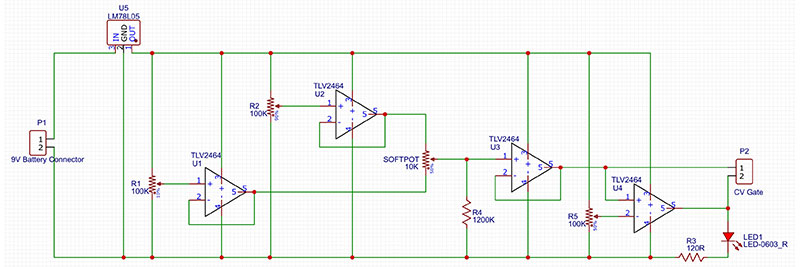
FIGURE 7. Circuit for the SoftPot ribbon controller.
Starting from the left-hand side, there’s a 9V battery connector, then an LM78L05 5V regulator that regulates the input voltage and provides a stable supply voltage for the rest of the circuit.
U1 to U4 are the four amplifiers in a TLV2464 quad op-amp chip. This is a low power, single supply, rail-to-rail op-amp that’s designed as a buffer for analog-to-digital converters (ADCs). I had some of these on hand, but you can use almost any single supply rail-to-rail op-amp here. It’s not critical.
The R1 wiper voltage is buffered by U1 and provides the voltage for one side of the SoftPot. The R2 wiper voltage is buffered by U2 and provides the voltage for the other side. Because of the buffering, these voltages are independently variable between 0V and 5V and are not affected by each other or the SoftPot.
The SoftPot is connected across the outputs of U1 and U2, and its wiper voltage is buffered by U3. The output of U3 is the CV output of the SoftPot ribbon controller.
This should be taken to a Eurorack compatible 3.5 mm jack socket and then to your synth. When the SoftPot is not touched, it’s open circuit. So, we use R4 to pull the U3 input (and therefore the U3 output) to 0V when this happens.
This ensures the output of the circuit is always between 0V and 5V. The value of R4 is high enough that it doesn’t really affect the rest of the circuit.
As well as a CV, we have a requirement to generate a gate. This needs to be 5V when the SoftPot is touched and 0V when it’s not. This is the job of op-amp U4, which is configured as a voltage comparator.
The voltage comparator gate circuit is shown in Figure 8.
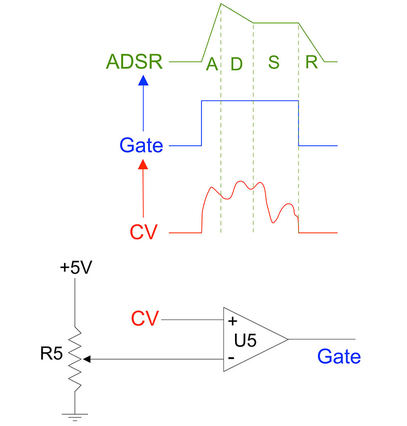
FIGURE 8. The gate circuit. The gate is triggered when the CV is greater than a few mV. The trigger level is set by potentiometer R5. If the gate triggers an ADSR envelope, note that there is a valid CV for only the ADS parts.
This is another incredibly useful circuit. When the voltage on the non-inverting (+) input of the op-amp is higher than the voltage on the inverting (-) input, the output voltage swings to the positive supply rail. When the voltage on the non-inverting input is lower than the voltage on the inverting input, the output swings to 0V.
Trimmer potentiometer R5 sets the inverting input of U4 to a few mV above 0V to ensure the gate is always 0V when the SoftPot is not touched. When it’s touched and it outputs more than a few mV, the gate goes high. I’ll explain how to set R5 correctly when I discuss setting up the SoftPot ribbon controller later.
The rest of the circuit is just an LED with current-limiting resistor R3 connected between the gate output and 0V. I used a 5V red LED with built-in internal resistor. The LED is essential because it gives visual feedback so you can set R5 to the right value to get the gate to trigger correctly and consistently.
Building the SoftPot Ribbon Controller
The circuit for the SoftPot ribbon controller is shown in Figure 7 and Figure 9 shows an example of a solderless breadboard layout.
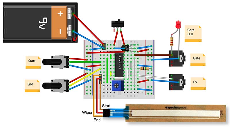
FIGURE 9. Example breadboard layout on a quarter size breadboard. WARNING: If you use 10-turn potentiometers, the wipers are not necessarily the middle pins as illustrated in this breadboard layout. Always check your potentiometers to identify the wipers before connecting them to the circuit!
The layout takes up exactly 1/4 of a full-size board, so it will fit on an Adafruit quarter size Perma-Proto board. This will give you a very neat result. All switches, potentiometers, LEDs, and jack sockets are panel mounted off-board as shown in Figure 1 and Figure 10.
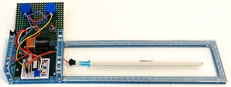
FIGURE 10. A 200 mm SoftPot ribbon controller showing the 1/4 size Perma-Proto board and point-to-point wiring to the front panel. The chassis is constructed from Totem Maker parts with a 3 mm acrylic sheet glued to the right-hand side of the frame to provide a smooth surface to stick the SoftPot to. The SoftPot connector is a JST-SM three-way female header.
I used 10-turn pots for R1 and R2, but normal pots might be okay depending on how you’re going to use the ribbon controller.
If you’re going to use it for pitch control, then 10-turn pots are pretty much essential. The maximum CV output is 5V, which at 1V per octave is five octaves, which is equivalent to 10 turns of the pot. This gives us two turns per octave, which is very comfortable.
On the other hand, with a single-turn pot, we get one turn per five octaves which is fiddly, but not entirely unusable. For example, the Behringer System 100 182 analog sequencer uses single-turn pots over a five octave range, although it probably shouldn’t.
There’s not much to say about constructing the circuit because there are so few components. As always, I suggest you build it in stages:
- Wire up the positive and negative power rails as shown in Figure 9 and check for continuity between the positive and negative rails on the left and right sides of the board with a digital voltmeter (DVM) set to a resistance range.
- Add the voltage regulator, switch, and battery, and check that there is +5V on the positive rail (red) when the switch is on. Disconnect the battery.
- Solder the rest of the wires and components to the board, using a socket for the TLV2464 op-amp.
Once the board is constructed, you need to add the off-board components. Figure 10 shows one of my 200 mm ribbon controllers opened to show the point-to-point wiring behind the front panel. There is quite a lot of this wiring because the multi-turn pots, LED, power switch, and sockets all live off-board.
Always use a good quality flexible multi-core wire for point-to-point wiring. The usual solid core hook-up wire is not suitable for this job and will make the process much more difficult. Also, solid core wire is not designed to be flexed and is prone to breakage.
There are a couple of things to be aware of when wiring up the front panel:
- Multi-turn potentiometers often have non-standard pinouts where the middle pin is not the wiper. I suggest you look to the manufacturer’s datasheet or use your DVM to identify the wiper before wiring them up. You can easily burn out a pot if you misidentify the wiper.
- You need to get the wiring of the 3.5 mm sockets right. Again, this depends on what sockets you use, so you’ll need to refer to the manufacturer’s datasheet or use your DVM. You won’t harm anything if you get signal and GND reversed, however.
Mechanical Construction
The key requirements for the mechanical construction of the SoftPot ribbon controller are:
- The SoftPot must be flat or on a smooth gentle curve.
- The wiring to the SoftPot must be secured so that there is no strain on the Crimpflex solder tabs.
- The design must be ergonomic (obviously!) so that the pots and ribbon are easy to operate.
The chassis in Figure 10 is constructed from the excellent Totem Maker system (see Resources). This is a flexible construction kit for makers that allows the construction of a range of chassis, robots, stands, etc., from a system of plastic ABS beams and plates. It’s ideal for this sort of project because you can easily play around with different designs to explore the ergonomics.
ABS beams and plates are simple to cut to size using the supplied Totem tools. I used an electric hand drill with a stepped drill bit to drill the holes in the front panel for the pots, switch, sockets, and LED.
ABS is a joy to work with, and this is probably the easiest chassis I have ever made. The chassis is robust and works well. Totem Maker is great fun to use.
The SoftPot needs to be stuck on a very flat, smooth surface but the Totem plates are not ideal for this because of the holes.
I glued a piece of 3 mm acrylic onto the frame sticking out of the right-hand side of the chassis to create a smooth, flat platform for the SoftPot to adhere to (see Figure 10).
The SoftPot has a self-adhesive backing and once it sticks to the acrylic plate, it’s not going anywhere! This means that you need to be careful to get the SoftPot correctly positioned the first time. I clamped a ruler to the acrylic plate to give me a reference edge to help me align it.
Note: If you’re interested in Totem, there’s a full review of another Totem product — the Totem Robotics Kit — in SERVO Magazine. This kit uses the Totem Maker system and other components to create an interesting range of seven remote control robots.
Setup and Use of the SoftPot Ribbon Controller
There is no left or right or up or down on this device! It all depends on how you orient the ribbon and how you set the potentiometers. However, for pitch use, CV should (according to the piano convention) increase from left to right.
I usually have the SoftPot Crimpflex connectors pointing to the left as in Figure 10, so that the chassis containing the pots and jacks is in easy reach of my left hand. This leaves my right hand free to operate the ribbon.
The left-hand pot controls the start voltage for the controller which is normally less than the end voltage and is controlled by the right-hand pot. However, as both pots have a full 0V to 5V range, you can set the voltages however you like and even make the device work backwards if you want.
The gate output must be set up as follows:
- Set the left pot fully left and the right pot fully right. This makes the range of the ribbon controller 0V (left-hand side) to 5V (right-hand side).
- Without touching the SoftPot, turn the trimmer pot on the circuit board so that the LED is off.
- Touch the left-hand end of the SoftPot and set the trimmer until the LED just lights.
- Touch the right-hand end of the SoftPot and, if needed, adjust the trimmer to keep the LED lit.
- Run your finger along the SoftPot. The LED should remain lit when you’re touching the SoftPot and go out when you’re not touching the SoftPot.
At this point, you might want to connect a DVM or oscilloscope to the SoftPot ribbon controller CV and gate outputs to see what happens when you touch the ribbon and adjust the left and right pots.
Note: Be sure to turn the SoftPot ribbon controller off when you’re not using it because it always draws about 0.1 mA current. This is because there is a resistance of about 50K between the 5V rail and ground.
That’s it! You’re ready to go. Connect the CV and/or gate to your synth and have fun!
Tuning
To use the SoftPot ribbon controller to precisely control pitch, it’s a good idea to create a template keyboard and tune the SoftPot ribbon controller to that template. I use templates made of paper or card stock and place them above the ribbon. An example is shown back in Figure 1.
You need to decide two things to construct your template:
- The number of notes you want over the span of the ribbon.
- The starting note.
If you want to play individual pitches, each note should cover enough of the ribbon so that you can hit it reasonably accurately. I find that 10 mm is about the minimum note width for my fingers. The starting note determines the pattern of white and black notes along the ribbon.
Consider the example keyboard template back in Figure 1. This has 20 notes over a 200 mm ribbon, so each note is 10 mm wide. This keyboard starts on G, so the sequence of 20 notes is G, G#, A, A#, B, C, C#, D, D#, E, F, F#, G, G#, A, A#, B, C, C#, and D, where naturals are white rectangles and sharps are black rectangles.
To tune the SoftPot ribbon controller to your template:
- Press the lowest note and adjust the left pot to set the appropriate pitch.
- Press the highest note and adjust the right pot to set the appropriate pitch.
For example, I often tune the keyboard in Figure 1 starting at G2 and finishing at D4. Because of the 1V per octave standard, all the other notes are in the right places between these two. If you’re lucky, your synth will have a built-in tuner, but if not, a cheap guitar tuner or tuner app for your phone will do the job.
Articulation and the Gate
Because the gate is generated directly from the CV using a comparator, the gate will always be 5V when the CV is a few mV above 0V and will fall to 0V when the CV falls to 0V (see Figure 8). This has implications for what kinds of articulation the SoftPot ribbon controller can support.
Let’s consider a synth keyboard to see how the SoftPot ribbon controller is different. Synth keyboards do at least two things:
- Output a constant pitch CV that changes when a key is pressed according to the 1V per octave standard.
- Output a gate CV that transitions from low (0V) to high (about 5V) when a key is pressed, and transitions from high to low when the key is released.
The important point to note is that the keyboard always outputs a valid pitch CV even when no key is pressed. This means that if you connect the pitch CV of a keyboard to an oscillator, the oscillator always sounds the last note that was pressed.
If you require articulation so that a note starts when a key is pressed and ends when a key is released, then you must use the gate CV to open a filter, open a VCA (voltage-controlled amplifier), or trigger an envelope to modulate the oscillator output.
Some synths also have simple analog switches that can be controlled by a gate (e.g., the Behringer 173 module). A simple “East Coast” style patch is shown in Figure 11, where the gate is used to trigger an ADSR (attack, decay, sustain, release) envelope that controls a VCA that modulates the volume of the oscillator.
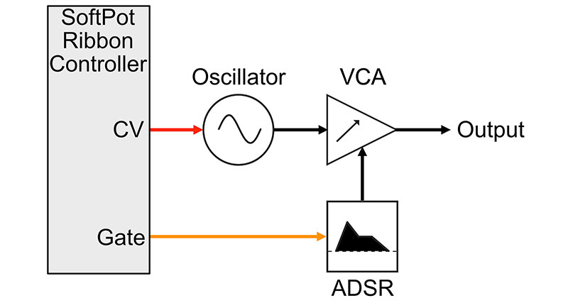
FIGURE 11. Simple “East Coast” style patch. The module symbols are from the Patch and Tweak website (see Resources).
Because the SoftPot ribbon controller CV falls to 0V when the gate is 0V, it behaves very differently to a keyboard. Consider the standard ADSR envelope shown back in Figure 8. The release part of the envelope is triggered by and extends beyond the falling edge of the gate.
This is fine for a keyboard because it holds the CV of the last key pressed. However, for the ribbon controller, the CV is 0V for the duration of the release stage.
So, the note would be correctly pitched for the ADS stages and then go to whatever pitch corresponds to 0V for the release stage. This generally isn’t what you want, so you need to set the release to be zero.
Future Directions
It would be nice to have an optional keyboard-like behavior for the ribbon controller that remembers the CV a few milliseconds before the ribbon is released. I did some experimentation with analog circuits to implement this.
I delayed the CV using a resistor/capacitor delay and used a sample and hold triggered by the negative-going edge of the gate to capture this delayed signal. However, I couldn’t get this to work reliably, so I haven’t included it here.
I suspect a digital approach might be more robust, or an approach using a bucket brigade delay line for a more controllable delay. If I manage to put together something that’s simple and reliable, I’ll write up an update.
Another feature I’d like to add to the SoftPot ribbon controller is touch sensitivity. Many analog synth keyboards output a CV that is proportional to how hard a key was pressed. This is most often used to control volume, but it can be used to control any synth parameter.
It’s quite easy to build an extended SoftPot ribbon controller that also outputs a CV that is proportional to the pressure applied to the ribbon as well as pitch CV and a gate. However, there’s no way to get pressure information from a SoftPot, so it’s necessary to add some extra pressure transducers to achieve this. This might well be a topic for a future article.
Summary
I hope you have enjoyed this article and take the time to build yourself a SoftPot ribbon controller. It’s an excellent addition to any analog synth! NV
Parts List
SoftPots: www.spectrasymbol.com
The 200 mm and 500 mm SoftPots are a good size for keyboards, and the 50 mm SoftPot is best used for other types of CV. All these SoftPots are also available in the UK and worldwide from Cool Components (www.coolcomponents.co.uk).
- SoftPot Membrane Potentiometer – 500 mm, SparkFun SEN-08681
- SoftPot Membrane Potentiometer – 200 mm, SparkFun SEN-08679
- SoftPot Membrane Potentiometer – 100 mm, Adafruit ID 178
- SoftPot Membrane Potentiometer – 50 mm, SparkFun SEN-08680
JST-SM Connector: LED Strip Pigtail Connector (three-pin), SparkFun CAB-14575
SIL IC Socket: 20-way TE Connectivity Straight Through Hole 2.54 mm SIL Socket, RS Components 681-1320
Adafruit Perma-Proto Quarter-sized Breadboard PCB - 3 Pack; ID 589
14-pin DIL Socket
TLV2464 Quad Operational Amplifier
LM78L05 5V Voltage Regulator
5 mm Red LED (if you use other colors, you should recalculate the current-limiting resistor)
Resistors 1200K, 120R
Trimmer 100K
100K 10-turn Potentiometers, 2 off