If you’re like me, you likely have a drawer or shoebox stuffed with assorted USB cables that are used to either charge or program a USB device. The problem often is that some cables may only be useful for charging, and which only have the +Vcc and ground wires intact with one or both data wires either broken or not connected in the first place.
How do you tell?
Figure 1 shows a simple test jig that will make it easier for you to quickly check the continuity of a four-conductor USB cable. The only parts needed are two (or more) “breakout” boards with female USB receptacles to match the ends of the USB cable you want to test and something to mount them on.
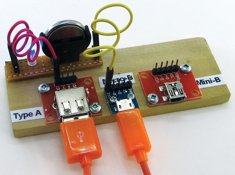
FIGURE 1.
(I used the USB type A, USB Micro-B, and USB Mini-B, and fastened them to a small piece of wood.)
Simply plug in your questionable cable to the appropriate mating female connectors on the test jig as shown and use an ohmmeter to check continuity by probing matching pin numbers on each breakout board. You can also verify the interconnection of pins 4 and 5 on an OTG cable (see sidebar).
What does OTG mean?
OTG is short for “On-The-Go.”
OTG USB cables are made with five pins at the Micro or Mini end instead of four. The extra pin (#4) is sensed by OTG capable Android devices to allow them to communicate with peripheral devices such as USB storage, keyboards, etc.
This pin is marked as “ID” on the breakout boards and is usually connected directly to ground pin 5. This is easily verified using the USB cable checker.
As an after-thought, I added the simple LED continuity checker shown at the top of Figure 1. It consists of just a lithium-ion coin cell like a CR2032, a blue LED from my junk box, and some jumper wires. It’s much easier to use than a multimeter.
The schematic is shown in Figure 2.
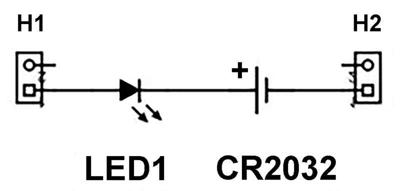
FIGURE 2.
The circuit can be built on a small piece of perfboard. A strip board layout is shown in Figure 3.
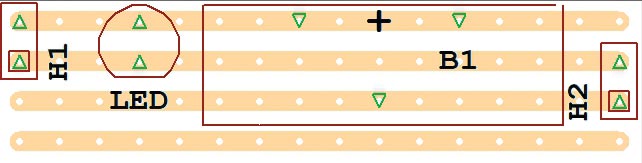
FIGURE 3.
A quick note on the coin-cell holder. I used a vertical holder because I had one. However, horizontal mounted holders may be more common, although they take up more space.
I hope you find this test jig handy. NV
Connecting an LED Directly to a Li-ion Coin Cell
At first glance, you may wonder why the LED doesn’t burn out when connected directly across a 3V coin cell battery without the usual series current-limiting resistor. The main reason is that coin cell batteries like the CR2032 already have a built-in internal series resistance (IR). This IR may range from 10 to 50 ohms or higher as the cell discharges.
Also note that blue or white LEDs are a good match to the battery, with Vfs of approximately 2.9V at 10 mA. If you use a red, green, or amber LED whose Vfs are lower (around 1.8 to 2.0 volts), it would be good practice to add an external series resistor of 68 ohms.
The little breakout boards are available from suppliers such as SparkFun. SparkFun part numbers are as follows:
- Type A USB: BOB-12700
- Micro-B USB: BOB-12035
- Mini-B USB: BOB-09966
- Jumpers F/F: PRT-11710 or 12796