A voltage reference is a zener diode-like semiconductor that produces an accurate fixed voltage; often, five or 10 volts. These are laser trimmed, and a 10 volt reference is available with accuracies up to ±0.0025 volts. My favorite voltage reference is the 10 volt Texas Instruments (TI) REF102 series available in accuracies of ±.01 volt (REF102A for $6), ±.005 volt (REF102B for $9), or the ±.0025 volt (REF102C for $12). This is no place to skimp, so I went with the REF102C for this project.
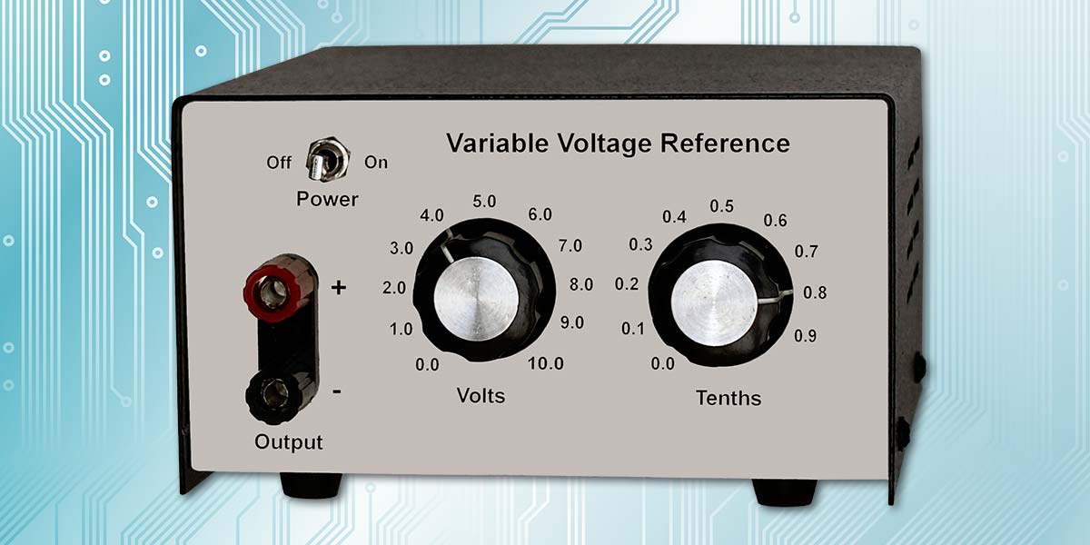
The downside to a voltage reference is that it only generates a single voltage and has limited current output. I decided to design a circuit that could generate any voltage between zero volts and 10 volts in 0.1 volt increments; for example, 4.8 volts with a basic accuracy of 10 millivolts and an output current of 100 milliamps (or one ampere with a power booster; see the TI OPA551 datasheet).
To achieve this accuracy requires analysis and mitigation of all possible sources of voltage errors. This will be discussed in the following sections.
Block Diagram
Figure 1 is a block diagram of my variable voltage reference (VVR).
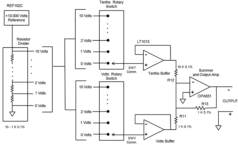
FIGURE 1. Variable voltage reference block diagram.
Starting at the left is the 10 volt REF102C which has an error of ±2.5 millivolts. This is within the 10 millivolt design goal. A 10 resistor ladder network (a voltage divider) breaks down the 10 volts into 10 integer volts as shown. This network is the first (and largest at about 10 millivolts) source of voltage error since the resistors are only 0.1%. I’ll address this later.
Next in the block diagram are the two front panel rotary switches: one for volts and the other for tenths of volts. It may seem strange that both switches are wired the same since the tenths switch works in tenth volt increments, but I’ll explain how this works shortly as well.
It’s very important that the resistor network not be loaded down by its following circuits, so I have a dual low input offset op-amp (LT1013) wired as a unity gain, very high impedance buffer. It has about one millivolt input offset to contribute to the error.
Now comes the fun part. The OPA551 is a very nice op-amp with a 200 milliamp output and a typical input offset of one millivolt. It also functions well as a summing amplifier.
The gain of the amplifier is the ratio of the feedback resistor (R13) divided by the input resistor (R11 for the volts path and R12 for the tenths path). Therefore, the gain for the volts path R13/R11 is one and the gain for the tenths path R13/R12 is 1/10. The summing amplifier simply adds the two inputs in this ratio.
For example, if the volts switch is set to four volts and the tenths switch is set to eight tenths, the output will be 4/1 plus 8/10 or 4.8 volts.
Notice that the OPA551 output is a negative voltage. The path from the REF102 to the final output is inverting, so plus 10 volts appears as minus 10 volts at the output. I could have used the REF102 as a negative reference (see the REF102 datasheet for how to do this), but I found that it performed better (less variance from the 10.000 volts) as a positive reference.
Another source of error is how the circuitry is assembled. I used a solderless plug-in breadboard for the initial testing and the results were bad. The wire leads on the resistors are thinner than the wire normally used (22 AWG) and they don’t make reliable contact, so I would see variations in the output by just touching one of the ladder resistors or tapping on the breadboard.
So, I went with an SB404 solderable breadboard and that completely solved the problem. This breadboard is very convenient and it may be possible to thicken the resistor leads by applying a thin coating of solder.
Reducing the Resistor Ladder Error
I chose 0.1% resistors for everything, but even this precision can give a 10 millivolt error — my entire error budget. The ladder resistor value isn’t the critical thing, but all resistors in the ladder should have the same (or close) value. This also applies to R11 and R13. They should both have the same value, but not necessarily the same value as the ladder resistors.
I needed a total of 10 1,000 ohm resistors for the ladder and two 1,000 ohm resistors for R11 and R13.
I bought 25 1,000 ohm resistors for 52 cents each from Digi-Key intending to select 10 resistors having close to the same value for the ladder. You also need two matched resistors for R11 and R13.
Now comes the challenge: how to measure each of the 25 resistors to better than .1%. A typical 3-1/2 digit handheld meter won’t do it; all resistors would read as 1,000 ohms! A 4-1/2 digit meter or better yet a 5-1/2 digit meter is required if we use this direct measurement method.
I used an alternate technique for measuring resistance called a Wheatstone Bridge method, with three 1,000 ohm 0.1% resistors from the batch of 25 and a +15 volts power source. The voltage measured by the bridge is quite small (low millivolts) but the two 3-1/2 digit meters I own read voltages as low as 0.1 millivolts.
A Wheatstone bridge is a simple circuit for measuring an unknown resistance by connecting it, so as to form a quadrilateral with three known resistances and applying a voltage between a pair of opposite corners.
I’m not sure of their accuracy, but we don’t need it to be absolute, only relative accuracy; that is, if one resistor gives a reading of 0.6 millivolts and another resistor gives a reading of 1.0 millivolts, we can expect that all resistors that give a reading of say zero to 1.0 millivolts will be very close in value.
Look at Figure 2. It’s a list of the measurements on the 22 resistors. The first column is the resistor ID number, the second column is the Wheatstone bridge measurement, and the third column is the actual resistance measured by an accurate 5-1/2 digit DVM. The list is sorted low to high on the Wheatstone bridge values.
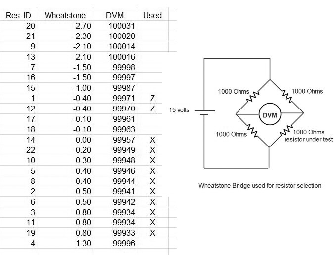
FIGURE 2. Ladder network resistor selection.
The highest value in the third column is 100031 (resistor 20) and the lowest is 99933 (resistor 19); a difference of .98 ohms — almost exactly 0.1% as expected.
If we look at the resistors having a Wheatstone voltage between 0 and 0.8, we get a high of 99957 (resistor 14) and a low of 99933 (resistor 19) — a difference of .24 ohms or about 0.02%. Five times better than 0.1% and a contribution to the error budget of about two millivolts!
Since the Wheatstone voltages measured are in the low millivolt range, it’s best if the resistors in the Wheatstone bridge are tack-soldered together at the ends of the resistor leads. This will reduce undesired voltage drops.
The Xs in the fourth column are the best candidates for the resistor ladder and the Zs are perfect for R11 and R13.
In Figure 2, I also show both the Wheatstone and the 5-1/2 digit DVM results. Clearly, if you have a 5-1/2 digit meter, you won’t have to do the Wheatstone measurements. I’m just trying to show how they correlate.
Detailed Circuit Diagrams
Figures 3 and 4 are the detailed schematics for the VVR principal circuits. They just add detail to the block diagram.
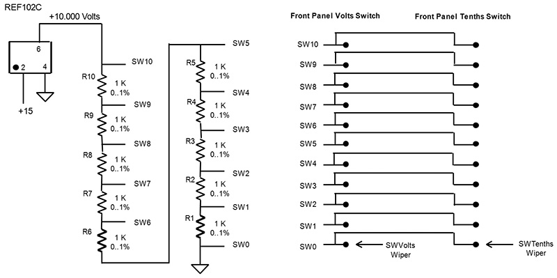
FIGURE 3. Voltage reference and switches.
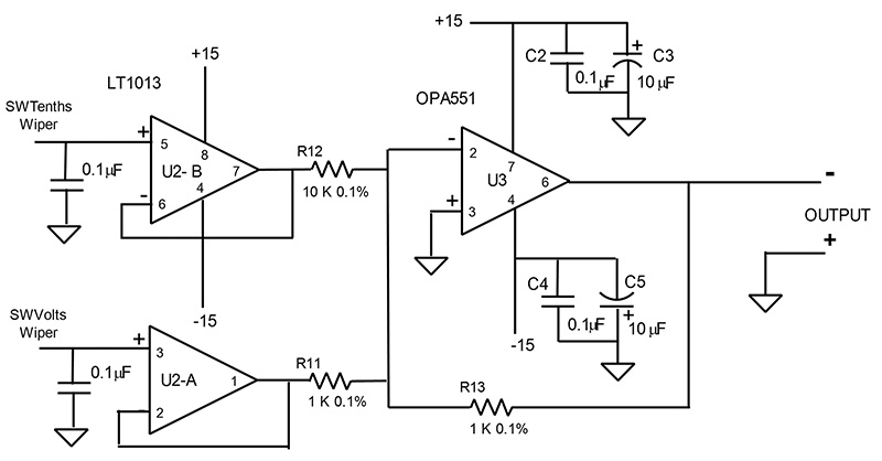
FIGURE 4. Voltage reference buffer and output amplifiers.
Power Supply
The VVR operates from ±15 volts at about 100 milliamps. It can be supplied in several ways; for example, AC/DC converters using normal house power for the AC. These are low priced and available with dual outputs of ±15 volts.
I get a little nervous about having 120 volts AC floating around in a metal box that I will come in contact with, so I looked at alternatives and found a great one: the Traco Power TEL 3-0523 (Digi-Key, $16). This is a DC/DC converter with 4.5V to 9V input and dual outputs of +15V and -15V at 100 milliamps each. The input and output are isolated from each other and it can be powered with a cell phone charger.
Unfortunately, these chargers typically use a USB to micro-USB cable. I couldn’t find a suitable panel mounted micro-USB jack, so I just changed the cable from a USB to a type M barrel cable. Or, you can just cut off the micro-USB connector and run the open end through a grommet and hard-wire it to the power supply.
I had to cut back the VVR output current to 80 milliamps because the OPA551 uses 20 milliamps internally.
Construction
Figure 5 is the assembly diagram for the principal components of the VVR. As I mentioned earlier, I prefer a soldered assembly for best accuracy and stability. I used the SB404 board for this project, but if you prefer a solderless assembly, then the assembly drawing shown in Figure 5 can be squeezed by two columns for the standard 30 column solderless breadboard.
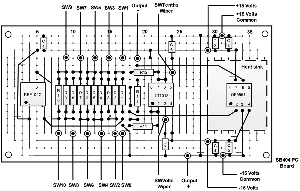
FIGURE 5. Voltage reference assembly drawing.
The worst-case power dissipation of the OPA551 in the VVR is about one watt which mandates a heatsink. I used thermal glue to bond a heatsink to the OPA551.
Performance
Figure 6 shows the actual VVR output at various volts and tenths switch settings. The VVR performance far exceeds my expectations! I think the accuracy of the ladder network is the main contributor at an additional cost of less than $7.
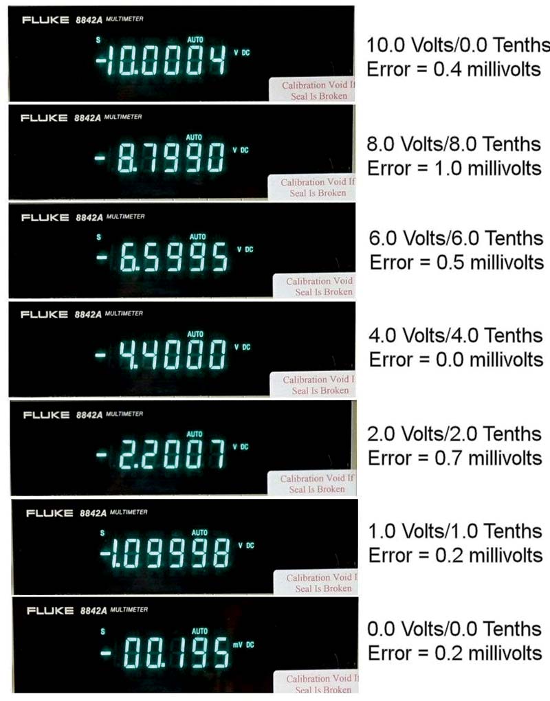
FIGURE 6. VVR performance test.
In addition, the output voltage with 0.0 volts/0.0 tenths is only 0.2 millivolts. This means that the sum of the input offsets of the LT1013 and the OPA551 is close to zero.
The VVR is expected to be used in a hobbyist workshop environment. However, it’s still important to evaluate what variations in performance to expect with changes in the environmental temperature.
The datasheets for the critical components are the REF102C; the resistors in the ladder and R11, R12, R13; the input offset voltage of the LT1013; and the input offset voltage of the OPA551. The parameter changes due to temperature are typically expressed in parts per million (ppm) per one degree Celsius change in temperature.
The REF102C has an output voltage change of 2.5 ppm per degree change in temperature. We need to determine how many millivolts this represents. The REF102C has a nominal output of 10 volts. We divide this by one million and get 0.00001 volts or .0.01 millivolts. Since the REF102C has a ppm of 2.5, we multiply the 0.01 by 2.5 and get 0.025 millivolts per one degree change in temperature.
The resistors have a resistance change of 25 ppm per degree change in temperature. Here, we take 1000 ohms and divide it by 1,000,000 and then multiply by 25 and get 0.025 ohms per degree change for each resistor. Each resistor sees only one volt, so the change is 0.025 divided by 1000 + 0.025 which is .000025 or .025 millivolts per one degree change in temperature.
Since there are 10 resistors in the ladder, we get 10 times 0.025 or 0.25 millivolts per one degree change in temperature. This seems like a lot but remember that all the resistors are subjected to the same temperature and will mostly experience the same change. The ratio of the resistors to one another doesn’t change much, and that’s what is really important.
The LT1013 input offset is a maximum of one millivolt over the full range of temperatures (-55°C to +125°C). It has a typical offset of 0.2 millivolts at room temperature.
The OPA551 has a typical input offset of one millivolt at room temperature and a maximum of five millivolts over the full range of temperatures (-55°C to +125°C).
What is the maximum error? It’s difficult to determine, but I think that based on my test unit results shown in Figure 6 (I didn’t do any component screening except for the resistors), your error should be less than three millivolts; probably less than two millivolts over ±20 degrees from normal room temperature.
Putting It to Work
An obvious first use for the voltage reference is to calibrate your digital and analog voltmeters. Set the variable voltage source to a value within the range selected on the DMM/VOM and adjust the voltage reading accordingly.
A more advanced application is to map out the accuracy and linearity of the analog-to-digital converter on your favorite microcontrollers. For example, ever wonder if the A/D converter on the Raspberry Pi is more accurate or more linear (or both) compared with the A/D converter on the Arduino? Well, here’s your chance to find out. NV
Parts List
| QTY |
DESCRIPTION |
SOURCE |
| 1 |
REF102C |
Digi-Key Part#: 296-17005-5-ND |
| 1 |
LT1013 |
Digi-Key Part#: 296-7044-5-ND |
| 1 |
OPA551 |
Digi-Key Part#: OPA551PA-ND |
| 25 |
1,000 ohm 0.1% resistors |
Digi-Key Part#: 10KADCT-ND |
| 2 |
10K ohm 0.1% resistors |
Digi-Key Part#: BC4503CT-ND |
| 1 |
Traco Power Supply |
Digi-Key Part#: 1951-2536-ND |
| 1 |
Solderable Prototyping Board |
Jameco Part#: 2191402 |
| 1 |
Heatsink |
Digi-Key Part#: 345-1089-ND |
| 1 |
Enclosure |
Jameco Part#: 208911 |
| 2 |
Rotary Switch |
Jameco Part#: 576501 |
| 2 |
Knobs |
Jameco Part#: 264955 |
| 1 |
Dual Banana Jack |
Jameco Part#: 2144024 |
| 1 |
Mini Toggle Switch |
Jameco Part#: 317287 |
| 1 |
Misc Capacitors |
|