In Part 1 of this series, I covered basic sweep alignment theory and construction/operation of an all-in-one sweep alignment instrument I dubbed the WhippleWay Sweep Alignment Board or WSAB, for short. In Part 2, I’ll describe sweep alignment procedures for AM and FM radios and give an actual example of each. We’ll begin with AM radio alignment which is the simpler of the two. If you want a more in-depth treatment of radio alignment, you might consider my Amazon book, Vintage Radio Alignment From Scratch. This two-part series is a “digest” of that book.
AM Sweep Alignment
To perform an AM sweep alignment, follow this procedure. A typical AM tube radio has a converter tube, IF amplifier tube, AM detector/audio amplifier tube, audio power amplifier tube, and a rectifier tube in the power supply. Refer to Figure 1.
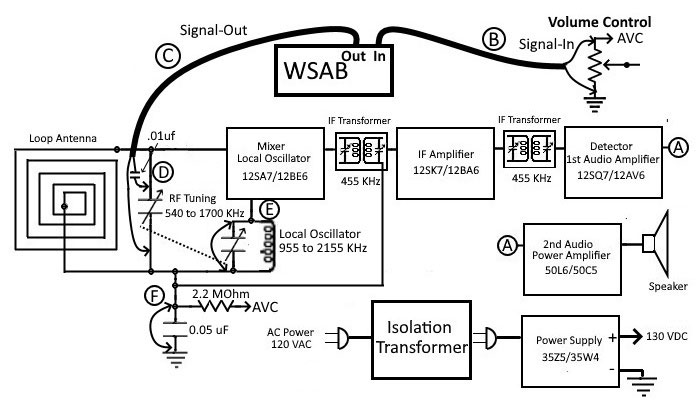
FIGURE 1. WSAB connections to sweep align an AM tube radio.
For AM IF amplifier alignment, the WSAB sweep signal is injected ahead of the first IF transformer and output is taken after detection. For vintage AM radios, the two IF transformers are adjusted to peak the displayed response curve at 455 kHz while maintaining as much symmetry as possible.
For tracking alignment, the receiver tuning dial is set to a frequency at the upper end of the tuning dial. An RF signal at that frequency is injected ahead of the converter and the AVC voltage is monitored while adjustments are made. It’s best to use the frequency recommended in the service manual. Otherwise, 1500 kHz is a good choice.
Important Notices
- When servicing radios, always use an AC isolation transformer* to safely isolate the radio’s chassis ground from the “hot” side of the AC power source. Failure to do so risks serious shock or even death.
- In addition, dangerous and lethal voltages are present when the radio is powered on. Keep fingers and metal tools away from circuitry during alignment. Again, failure to do so risks serious shock or even death.
- Use only non-metallic tools** to avoid the danger of shock and the creation of a short circuit.
If you are unwilling or unable to comply with these notices, do not attempt alignment of any radio or tuner! Defer instead to a trained and competent technician or engineer.
* Such as Jameco’s Isolation Transformer 120 VAC at 300 VA; order #181315.
** Such as Amazon’s Aven 13016 9 Piece Anti-Static Alignment Tool Kit.
Before starting, make these two accessories. To make the capacitor accessory, solder a 0.01 µF capacitor to a hook-type clip as in Figure 2A. Keep the leads short as shown. The capacitor accessory is used to block tube grid DC voltage from the WSAB input circuit.
To make the resistor accessory, solder a 2.2 mohm half watt metal film resistor to a hook-type clip as in Figure 2B. The resistor accessory is used to reduce loading effects of the WSAB signal input circuit during certain measurements.
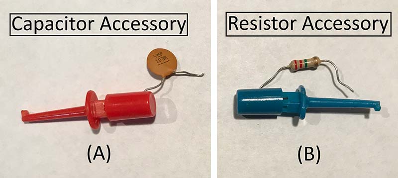
FIGURE 2. (A) Capacitor and (B) resistor accessories used in radio alignment.
For AM IF alignment, follow these steps:
Step 1. With the radio powered off, fully open the variable tuning capacitor.
Step 2. Clip WSAB signal-in to the non-ground terminal of the volume control and signal-in ground to the ground terminal (DC ground). See “B” in Figures 1 and 3.
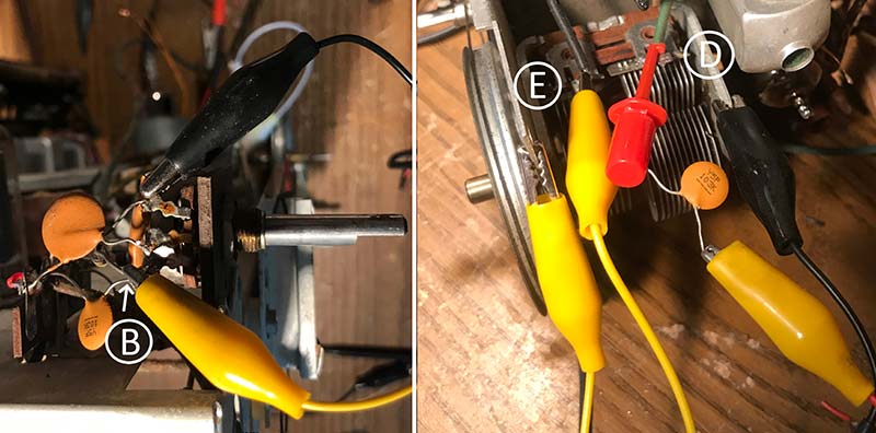
FIGURE 3. WSAB AM alignment connections: (A) signal-in to volume control; (B) signal-out to tuning capacitor.
Why use the volume control ground terminal as signal-in ground? The radio chassis is not always connected directly to the power supply negative (DC ground) and therefore may not be suitable for measuring DC voltages. (Refer to Sidebar 1.) The volume control ground terminal is a good choice for DC ground because it usually connects to the power supply negative. If in doubt, check the service manual schematic or find a suitable DC ground (with power off, of course).
Sidebar 1
Making a distinction between “Chassis Ground” and a “DC Ground” is important. A radio’s metal chassis is not always connected to the negative DC supply. In this case, Chassis Ground and DC Ground are not electrically the same; thus, two symbols are needed. Refer to Figure A.
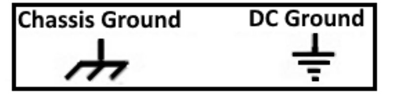
Figure A.
Given this distinction, to measure a DC voltage, use only the DC ground. When injecting RF and IF signals, use the chassis as ground and make the ground connection as close as possible to the injection point. The negative DC supply (DC ground) is easily identified by locating the negative (usually black) lead of the tubular electrolytic capacitor or the metal tabs of a can-type electrolytic.
convenient DC Ground when measuring AVC voltage is the grounded terminal of the volume control. To locate it, face the volume control head-on with the three terminals on top. The right most terminal is usually DC ground. If in question, a quick visual or ohmmeter check will confirm it as DC ground.
Step 3. Connect the WSAB signal-out with the 0.01 µF capacitor accessory to the terminal of the larger of the two tuning capacitor gangs. This is where the loop antenna connects to the tuning capacitor. Clip signal-out ground to the frame of the tuning capacitor. See point “D” in Figures 1 and 3.
Step 4. Connect a clip lead between the smaller tuning capacitor terminal and the tuning capacitor frame. See point “E” in Figures 1 and 3. This disables the local oscillator and reduces noise and erroneous signals that could affect the sweep display.
Step 5. The radio’s automatic volume control (AVC) must be disabled during sweep alignment. To do this, find the large value resistor (usually 2.2 mohm) that connects between the AM detector/volume control and the converter/IF amplifier tuned circuits. Refer again to Figure 1. Connect a clip lead between the converter/IF side of the resistor (point “F” in Figure 1) and DC ground.
Step 6. Turn radio power on and let it “warm up” for 20-30 minutes to stabilize components that might be affected by heat during alignment.
Step 7. Turn the WSAB on. The default sweep mode is Mode 0 “AM IF (-) kHz,” AM IF alignment with a center frequency of 455 kHz. The display will show negative input voltages from the bottom of the plot area.
Step 8. Set the Sweep Input Gain at 50% (a quarter turn from fully counterclockwise). Bring the sweep output signal slowly up from fully counterclockwise until a peaking response curve fills two-thirds of the plot area.
Adjust the Sweep Input Gain as needed. Remember that too high a signal can cause overload and detuning!
Two types of IF transformers are commonly found in AM radios. Capacitive-tuned types have two screws on the top of the IF can: one for the tuned primary adjustment and the other for the secondary. Permeability tuned IF transformers use two ferrite slugs. The primary slug is usually accessible from the bottom of the IF can and the tuned secondary slug from the top.
For both IF types, use only non-metallic tools to avoid the danger of shock and the creation of a short circuit. In addition, the presence of the metal can affect tuning of the coils. An excellent set is available on Amazon by searching for “Aven 13016 9 Piece Anti-Static Alignment Tool Kit.”
Step 9. Starting with the second IF transformer, une both adjustments to visually peak the output while maintaining symmetry about the center frequency. As tuning proceeds, keep the signal level and output voltage as low as possible. Move to the first IF transformer and repeat the tuning procedure.
Repeat the entire tuning procedure to make any final adjustments to the response curve. See Figure 4 for a representative example of how a good response curve will look.
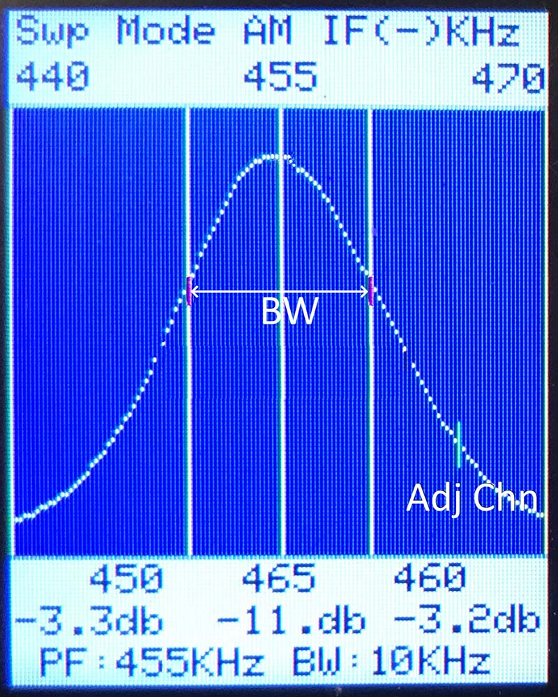
FIGURE 4. AM IF sweep response showing bandwidth and adjacent channel attenuation.
For the AM alignment example (Figure 4), the TFT display provides the following information:
- Peak Frequency (PF) = 455 kHz.
- Voltage Gain at ±5 kHz markers = -3.3 dB and -3.2 dB, indicating good symmetry.
- Bandwidth (-3 dB frequencies) = 10 kHz; a little wide but acceptable for a typical AM radio.
- Adjacent Channel Voltage Gain at the IF frequency plus 10 kHz = -11 dB; not great but acceptable for a typical AM radio.
Note: The Variable Frequency Marker in Figure 4 (the short vertical line on the right edge of the response curve) was moved to 465 kHz with the frequency controls to check the adjacent channel gain (-11 dB); 465 kHz is the frequency where an adjacent station’s signal would fall after conversion. The lower adjacent frequency (445 kHz) could be checked in a similar manner.
The last two steps are the tracking (RF alignment) procedure.
Step 10. Turn radio power off for a short time while making these changes. Remove all test connections to the radio. Connect the voltmeter across the volume control.
Regarding the voltmeter, a battery-powered digital multimeter of good quality should be used. It should have an input impedance exceeding one mohm. Because of potential grounding issues, AC line-powered multimeters are not recommended for alignment use.
Step 11. Change the tuning dial to 600 kHz. Turn on the WSAB and press the Select Option button once to move to the Change Center Frequency option. Use the Frequency Step and Frequency controls to change the center frequency to 600 kHz. The WSAB is now performing the function of a signal generator with a stable and accurate 600 kHz signal. Clip the WSAB signal output to a fixed position near the loop antenna. The idea is to bring WSAB’s 600 kHz signal near the loop antenna without directly connecting to it.
Step 12. Turn the radio power on and wait a few minutes for it to come back to operating temperature. Tune in the WSAB signal and relocate the tuning dial pointer to the 600 mark.
Step 13. Change the tuning control to 1500 kHz on dial marker. On the WSAB, use the Frequency Step and Frequency controls to change the center frequency to 1500 kHz.
Step 14. Adjust the Sweep Output Level to 25%. Make two adjustments on the variable capacitor. First, adjust the trimmer capacitor on the smaller of the two tuning capacitor gangs (local oscillator) to locate and peak the 1500 kHz signal on the voltmeter. Adjust the Sweep Output Level to keep the AVC voltage in the range of -1 to -2 volts. Second, adjust the trimmer capacitor on the larger of the two tuning capacitor gangs (the RF input) for a maximum reading on the voltmeter. Use only enough signal strength to give a readable indication on the voltmeter.
Step 15. Repeat steps 10 to 14 until minimal readjustments are needed.
That’s all there is to it. If problems are encountered at any point, circuit components could be at fault. Troubleshooting these issues is beyond the scope of this article. Consult the Internet. Many good sources are found there.
FM Sweep Alignment
If the FM radio’s service documentation is available, it generally includes a sweep generator alignment procedure. Following it is a good idea. If documentation is not available, the alignment procedure described below generally works well.
Most consumer AM/FM radios were designed so they could be aligned with a signal generator and voltmeter. The alignment procedure described here takes advantage of this by peak-aligning the IF stages with a signal generator and voltmeter, then visually “touching up” the IF response curve and detector S-curve.
For IF stage alignment, the WSAB is used as an accurate, highly stable signal generator. While in any FM mode, simply press the Select Option button to select the Change Center Frequency option. The Center Frequency is output as an unmodulated 10.7 MHz signal.
FM radios generally use permeability tuned IF transformers. Adjustment is made using two ferrite slugs: the primary slug accessible from the bottom of the IF can and the secondary slug from the top.
Use only non-metallic tools to avoid the danger of shock and the creation of a short circuit. In addition, the presence of the metal can affect tuning of the coils.
A complicating factor in FM sweep alignment is that three FM detector types are found in FM radios, each with a somewhat different alignment procedure. The discriminator (Figure 5A) and balanced ratio detector (Figure 5B) will be described next.
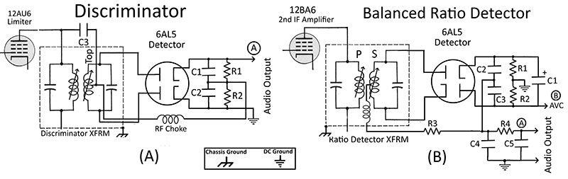
FIGURE 5. FM detectors: (A) discriminator; (B) ratio detector.
The third type — the unbalanced ratio detector — looks like the balanced version of Figure 5B except that resistors R1 and R2 are replaced by a single resistor with no ground connection. Also, one end of capacitor C1 (usually the positive lead) is grounded. Alignment procedures for the unbalanced version vary and will not be covered here. Referral to the radio’s service manual is recommended.
Occasionally, FM designs include automatic volume (gain) control. It must be disabled to do sweep alignment. This situation can be recognized by inspecting the biasing of each IF stage input circuit. If these input circuits are returned to DC ground, then no AVC is in use.
If instead a connection through a resistor (usually 470K ohm or larger) to the FM detector or limiter stage is found, this is likely the AVC supply circuit. To disable it, connect a clip lead between the IF amplifier side of the resistor and the DC ground.
Be sure to again follow the Important Notices given previously.
Discriminator Alignment
The discriminator has less distortion than the ratio detector but has no immunity to amplitude type noise. For this reason, it requires two IF stages for amplification and a limiter stage to reduce amplitude noise.
The alignment procedure for the discriminator consists of three phases: (1) sweep pre-alignment of the discriminator; (2) signal generator/voltmeter alignment of the IF stages; and (3) final sweep adjustments to obtain a satisfactory S-curve.
Phases 1 and 3 use the WSAB in sweep mode; phase 2 uses the WSAB as a signal generator along with a voltmeter.
Unless instructed otherwise, adjust the Sweep Output Level and Sweep Input Gain to the lowest settings that produce a readable indication on the WSAB display or voltmeter.
One of the nagging problems of FM alignment is reception of a sweep frequency harmonic through the radio’s antenna. This can severely interfere with IF and S-curve alignment. In the AM case, a short circuit across the local oscillator tuning capacitor solved the problem.
With FM radios, it’s not that simple. Most often, the local oscillator coil is permeability tuned with a moving ferrite core, so there’s no convenient variable capacitor to short circuit.
Short circuiting the fixed tuning capacitor would work; however, the relevant circuitry is frequently enclosed in a shielded metal box making access impractical.
The signal injection accessory of Figure 6 is a workaround.
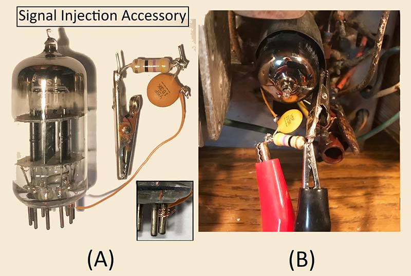
FIGURE 6. FM injection accessary: (A) close-up detail; (B) in-circuit connection.
Cut a 2-1/2 inch length of No. 30 or smaller wire (wire wrap wire is ideal) and strip 1/2 inch of insulation from both ends. Wrap one end around the converter tube’s mixer grid pin (grid G1 of a triode or grid G3 of a pentagrid converter). Refer to the inset in Figure 6A. The pin number will vary depending on the tube type. In the case of a dual triode, the mixer could be either section. Without a schematic, circuit tracing may be necessary to identify the mixer triode. It’s the section that feeds the first IF transformer.
Cut the leads of a 47Ω 1/2 watt metal film and a 0.01 µF disc capacitor to 1/2 inch, then solder them together as shown in Figure 6A. Solder a small alligator clip to the free end of the resistor. Solder the free end of the capacitor to the free end of the No. 30 wire. Leave small “pig tails” for connecting the signal generator.
Carefully insert the tube back in its socket. Clip the alligator clip to the ground shield of the converter tube (chassis ground) as shown on the right in Figure 6. The accessory’s low impedance path between signal grid and chassis ground short circuits signals coming in the radio’s front end eliminating any RF interference. Do not connect the signal generator to the injection accessory at this time.
The alignment example discussed next is a Zenith AM/FM table radio.
Phase 1: Visually Pre-align Discriminator
Step 1. Turn the radio on and let it warm up for 20-30 minutes to stabilize components that might be affected by heat during alignment.
Step 2. Turn the WSAB on. Change the sweep mode to Mode 2 “FM IF (-) MHz” (FM IF alignment with a center frequency of 10.7 MHz).
Before continuing, be sure that the radio is not receiving a harmonic of the WSAB through the antenna and RF circuits. The shorting effect of the signal injection accessory should suppress any stray signals but check anyway. Turn the Sweep Output Level to maximum output (fully clockwise). Tune the radio around 108 MHz, listening for the WSAB signal in the speaker. Since it’s unmodulated, listen for changes in noise level. Pick a receive frequency where no signal is heard.
Step 3. Connect the WSAB signal-in to point “B” in Figure 7 and the signal-in ground to DC ground.
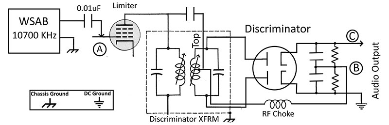
FIGURE 7. WSAB connections for discriminator pre-alignment.
Step 4. Clip the 0.01 µF capacitor accessory to the control grid of the limiter tube; point “A” in Figure 7. Clip the WSAB’s signal-out to the free end of the capacitor and the signal-out ground to a nearby chassis ground.
Step 5. Turn the discriminator secondary slug (usually the top adjustment) counterclockwise until it reaches the upper end of its travel. With the Sweep Input Gain at 50% (a half turn from fully counterclockwise), increase the Sweep Output Level slowly until a peaked response curve appears on the WSAB display. Readjust the Sweep Input Gain as necessary. Adjust the primary of the discriminator transformer (usually the bottom tuning slug) for a peak at 10.7 MHz (Figure 8A).
Step 6. Move the WSAB signal-in from point “B” to point “C.” Press the Select Mode button and change to Mode 5 “FM DS (+-) MHz.” Adjust the secondary of the discriminator (usually the top adjustment) for a symmetrical double S-curve as in Figure 8B.
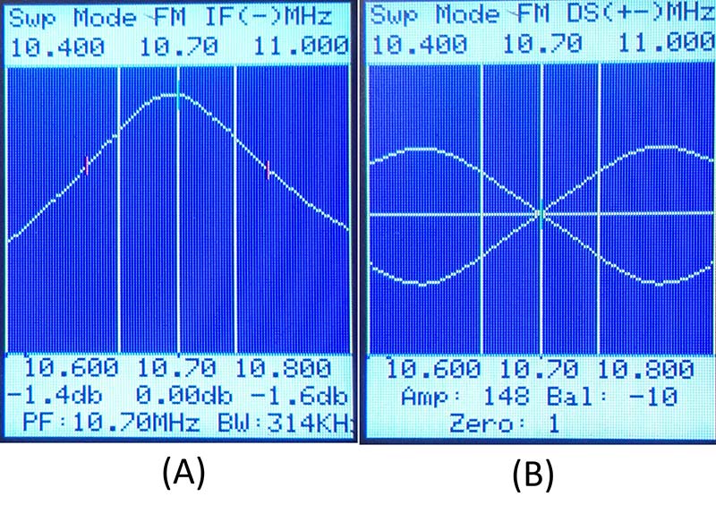
FIGURE 8. Discriminator pre-alignment: (A) primary response curve; (B) secondary response curve.
Several turns clockwise will be needed before noticing a significant change in the S-curve crossover point. A touch-up of the primary of the discriminator may be needed.
The “Bal” and “Zero” values shown at the bottom of the display are helpful when using the SS and DS modes. Bal is the difference in the S-curve’s raw A/D values at the lower and upper marker frequencies (the ±100 kHz markers). Zero is the S-curve’s raw A/D value at 10.7 MHz. Both Bal and Zero are zero for an ideal S-curve. Realistically, a “good” S-curve will have values for Bal from -25 to 25 and Zero between -5 to +5.
In most cases, if the Zero and Bal factors are in an acceptable range, the intermediate portion of the S-curve will be reasonably straight. If it’s not, adjust the primary of the discriminator transformer (usually the bottom slug) for straightness. Be willing to trade imbalance (higher Bal value) for straightness.
Phase 2: Align IF Stages
Step 1. Connect the 2.2 mohm resistor accessory to the limiter grid-leak resistor; point “A” in Figure 9. Connect the voltmeter to the free end of the resistor.
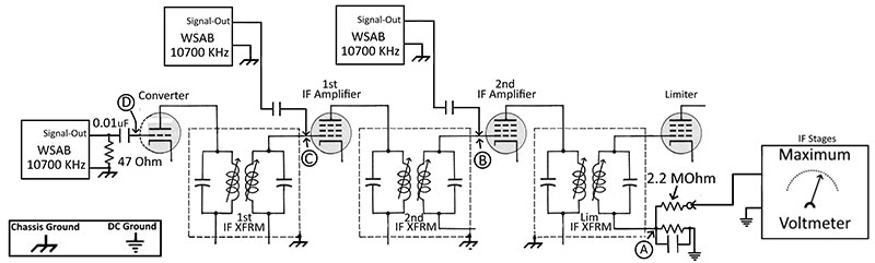
FIGURE 9. WSAB connections for IF and limiter alignment.
Step 2. Press the Select Option button to select the Change Center Frequency option. The WSAB is now acting as a signal generator at 10.7 MHz.
Step 3. Move the WSAB signal-out and capacitor to the control grid of the second IF amplifier; point “B” in Figure 9. Clip the signal-in ground to a nearby chassis ground. Bring up the Signal Output Level watching for a readable indication on the voltmeter.
Step 4. Adjust the primary and secondary of the limiter transformer to maximize the voltmeter reading. Since these adjustments may interact, repeat until no change is noted.
Step 5. Repeat steps 3 and 4 for the first IF amplifier. Use point “C” for signal injection and adjust the second IF transformer.
Step 6. Connect the WSAB signal-out across the 47 ohm resistor of the signal injection accessory.
Step 7. Use the output scaling switch and Sweep Output Level control to get a readable indication on the voltmeter. Readjust the Sweep Input Gain as necessary. If the output signal level is too strong even at minimum control settings, clip the WSAB signal-out to the outside of the 0.01 µF disc capacitor. This “loosely coupled” arrangement should work with increased gain and signal output.
Adjust the primary and secondary of the first IF transformer for a maximum reading on the voltmeter. For recent FM radios, the first IF transformer is sometimes built into the shielded converter box.
In this case, the IF transformer’s two ferrite slugs are accessible from the top and/or bottom of the box. A very small bladed insulated screwdriver is needed for this. One such tool is included in the insulated tool kit mentioned previously.
Phase 3: Visual Touch-Up of IF and S Curves
Step 1. Disconnect the voltmeter. Clip the WSAB signal-in to the free end of the 2.2 mohm resistor and the signal-in ground to DC ground.
Step 2. Press the Select Option button multiple times until the sweep mode starts. The WSAB should be in Mode 2 “FM IF (-) MHz.” Adjust the Signal Output Level and Signal Input Gain to get a peaking response curve. In theory, it should be a symmetrical peak, but experience has shown this is not always the case. Refer to Figure 10A.
The response curve was peaked but decidedly lopsided! A slight touchup of the IF adjustments cleared up the problem as shown in Figure 10B.
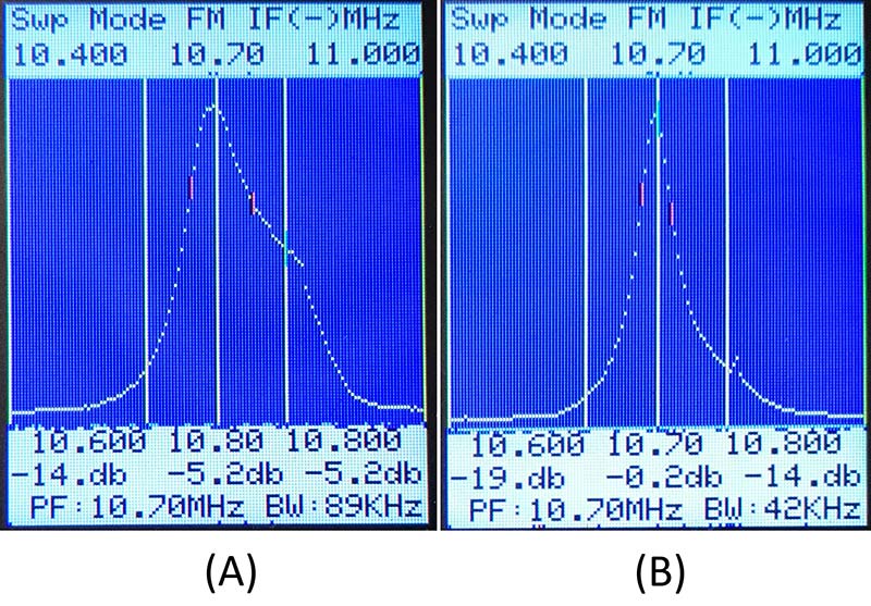
FIGURE 10. IF response curves: (A) after signal generator/ voltmeter alignment; (B) after sweep touch-up.
While it appeared “too” sharp, I decided to leave it that way; “peaked” as the radio’s designers probably intended!
The next step is to check the S-curve. Two sweep mode options exist: (1) use the SS (Single Sweep) mode; or (2) use the DS (Double Sweep) mode. The choice is a matter of preference. The Double Sweep mode is my choice for discriminator radios because balance, symmetry, and correct centering at 10.7 MHz are most easily visualized.
Step 3. Move WSAB signal-in to point “C” in Figure 9 and the signal-end ground to DC ground. Press the Sweep Mode button until the DS mode shows on the TFT display. Adjust the Sweep Output Level and Sweep Input Gain to give a noise-free double S-curve (Figure 11A).
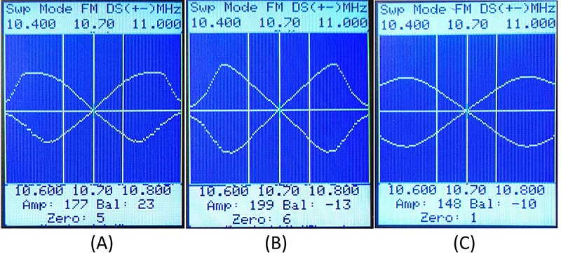
FIGURE 11. Discriminator response curves: (A) after IF alignment; (B) after sweep touch-up; and (C) showing effect of limiter action with a strong signal.
Too strong a signal and limiter action will obscure some of the visual detail needed to correct a misshaped response curve.
Step 4. If necessary, make small changes (usually less than a half turn) to the IF and discriminator transformers. The goal is: (1) good symmetry between the top and bottom response curves; (2) a center crossing point at 10.7 MHz (zero value of -5 to +5); (3) good balance between lower and upper marker frequencies (Bal value of -25 to 25); and (4) a straight line between lower and upper marker frequencies.
As a rule, IF transformers other that the discriminator transformer affect response curve shape — especially the first IF transformer at the converter/mixer. The primary of the discriminator transformer (usually the bottom slug) affects the amplitude of the response curve without changing the shape.
Finally, the secondary of the discriminator transformer (usually the top slug) affects the center crossing of the double S-curve that should be at 10.7 MHz. Figure 11B shows the satisfactory S-curve after making slight adjustments.
The response curve has: (1) good symmetry top to bottom; (2) good balance in amplitude between peaks; (3) a center crossing at 10.7 MHz; (4) a straight line between lower and upper markers; and (5) a rapid fall of amplitude in the region of adjacent station frequencies.
Figure 11C shows the S-curve after a very strong signal activates the limiter. Note that good S-curve characteristics prevail except for adjacent channel attenuation, which has suffered because of overloading in the IF stages! This is to be expected, as the radio has no automatic gain control for RF or IF stages.
Tracking Alignment
Tracking alignment for a FM radio is best done following service documentation. If unavailable, the procedure discussed next can be followed provided the radio uses trimmer capacitors to align the upper end of the FM band.
For most recent tabletop radios, the two trimmer capacitors are accessible on the top of the shielded converter box. An insulated bladed screwdriver is needed to make the adjustment.
Step 1. The WSAB does not directly tune to the lower end of the FM band, but it’s possible to use a sixth harmonic of a center frequency to do tracking alignment. Clip the WSAB signal-out to the insulation on a short length of wire connected to one of the FM antenna terminals. While in any FM mode, press the Select Option button to select the Change Center Frequency option. Use the frequency controls to change the center frequency to 15000 kHz (one-sixth of 90 MHz).
Connect the voltmeter across the limiter’s grid-leak resistor as in the Phase 2 alignment discussed previously. Use the radio’s tuning control to tune in the WSAB’s signal, then adjust the dial pointer to place it at 90 MHz.
Step 2. Change the dial pointer to 108 MHz. Use the frequency controls to change the center frequency to 18000 kHz (one-sixth of 108 MHz). Using the WSAB frequency controls, move in small steps up and down from 18000 kHz until the WSAB’s signal is verified by readings on the voltmeter. The purpose of this is to know what to listen for in the next step.
Step 3. Change the WSAB’s frequency back to 18000 kHz. The dial pointer is still set to 108 MHz. If the local oscillator trimmer is not known, try both to see which one “tunes in” the WSAB signal. When the local oscillator trimmer is identified, adjust it for maximum reading on the voltmeter. Keep the signal level low; just enough to provide a readable indication on the voltmeter.
Step 4. The remaining trimmer adjusts the converter’s RF gain. Adjust it to peak the voltmeter reading. For both adjustments, use only enough signal to give a readable indication on the voltmeter.
Step 5. Repeat steps 1 to 4 until minimal readjustments are needed.
Turn radio power off and remove all test connections. Turn radio power on and perform a listening test to check the alignment.
Ratio Detector Alignment
For low-end AM/FM radios, the ratio detector is a popular choice. Because it’s inherently noise immune, the limiter stage is not needed, thus reducing manufacturing costs. Alignment follows the same basic procedure as the discriminator with a few changes to signal injection and measurement points.
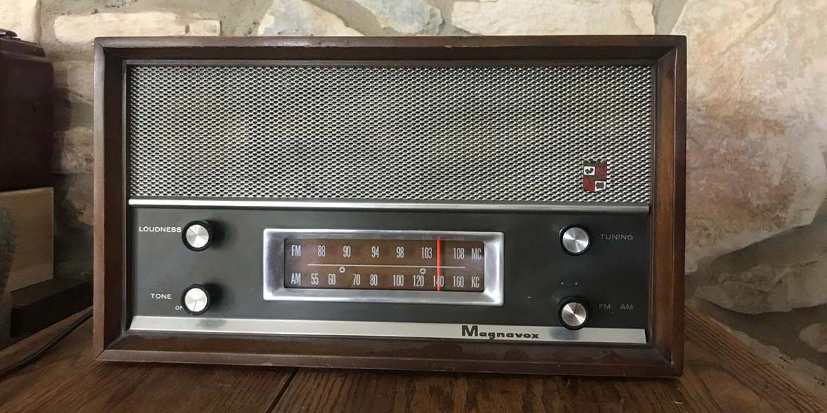
The example alignment that follows is that of the Magnavox radio mentioned at the beginning of this article.
Phase 1: Visually Pre-align Ratio Detector
Step 1. Turn the radio off. Tune the radio’s dial to the upper end of the FM range (108 MHz). Install the signal injection accessory as in Figure 6. Disconnect the negative lead of the stabilizing capacitor Cs from the AVC line at point “B” in Figure 12.
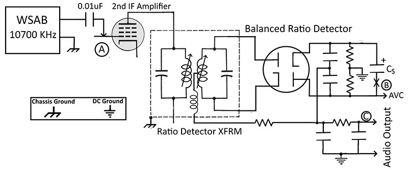
FIGURE 12. WSAB connection for ratio detector alignment.
Step 2. Turn on the radio and let it warm up for 20-30 minutes to stabilize components that might be affected by heat during alignment.
Step 3. Turn the WSAB on. Change the sweep mode to Mode 2 “FM IF (-) MHz” (FM IF alignment with a center frequency of 10.7 MHz).
Before continuing, be sure that the radio is not receiving a harmonic of the WSAB through the RF circuits. Turn the Sweep Output Level to maximum output (fully clockwise). Tune the radio around 108 MHz, listening for a signal in the speaker. Since it’s unmodulated, listen for changes in noise level. Pick a frequency where no signal is heard.
Step 4. Connect the WSAB signal-in to the AVC side of point “B” and the signal-in ground to DC ground.
Step 5. Clip the 0.01 µF capacitor accessory to the control grid of the second IF amplifier; point “A” in Figure 12. Clip the WSAB’s signal-out to the free end of the capacitor and the signal-out ground to a nearby chassis ground.
Step 6. Turn the ratio detector secondary slug (usually the top adjustment) counterclockwise until it reaches the upper end of its travel. With the Sweep Input Gain at 50% (a half turn from fully counterclockwise), bring the Sweep Output Level up slowly until a peak is visible on the WSAB display.
Readjust the Sweep Input Gain as necessary. Adjust the primary of the ratio detector transformer (usually the bottom adjustment) for a peak at 10.7 MHz. Refer to Figure 13A.
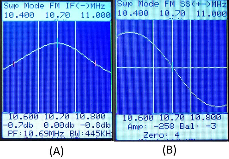
FIGURE 13. Ratio detector pre-alignment: (A) primary response curve; (B) secondary response curve.
Step 7. With the radio powered off, reconnect the negative lead of Cs to the AVC line. Move the WSAB signal-in from point “B” to point “C.” Press the Select Mode button and change to Mode 5 “FM SS (+-) MHz.” Adjust the secondary of the ratio detector (usually the top adjustment) for a symmetrical S-curve as in Figure 13B. Several turns clockwise will be needed before noticing a significant change in the S-curve crossover point. A touch-up of the primary of the ratio detector may be needed. (Of course, the DS mode can be used if preferred.)
Phase 2: Align IF Stages
Step 1. Connect the WSAB signal-out across the 47 ohm resistor of the signal injection accessory.
Step 2. Connect the voltmeter to the AVC line; point “B” in Figure 14. Connect the signal-in ground to DC ground. Press the Select Option button to select the Change Center Frequency option. The WSAB is now acting as a signal generator at 10.7 MHz.
Step 3. Set the WSAB Sweep Input Gain at 50%. Use the output scaling switch and Sweep Output Level control to get a readable indication on the voltmeter. Readjust the Sweep Input Gain as necessary.
Step 4. Adjust the primary and secondary of the second IF transformer to maximize the voltmeter reading. Since primary and secondary adjustments may interact, repeat until no change is noted.
Step 5. Adjust the primary and secondary of the first IF transformer for a maximum reading on the voltmeter. For recent FM radios, the first IF transformer is sometimes built into the shielded converter box. The IF transformer’s two ferrite slugs are accessible from the top and/or bottom of the box.
A very small bladed insulated screwdriver is needed for this.
Phase 3: Visual Touch-Up of IF and S-Curves
Step 1. Disconnect the voltmeter. With the radio powered off, disconnect the negative lead of the stabilizing capacitor Cs from the AVC line. Clip the WSAB signal-in to the AVC line; point “B” in Figure 14.
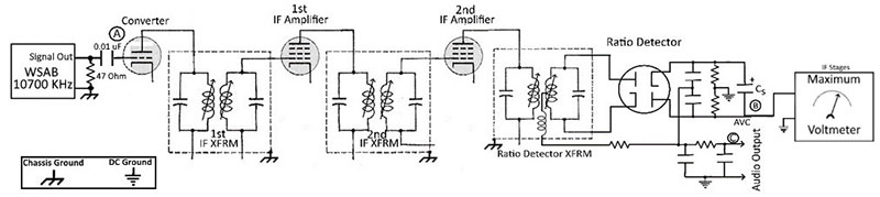
FIGURE 14. WSAB connections for IF alignment.
Connect the signal-in ground to DC ground.
Step 2. Press the Select Option button multiple times until the sweep mode starts. The WSAB should be in Mode 2 “FM IF (-) MHz.” Adjust the Signal Output Level and Signal Input Gain to get a peaking response curve. Slightly touch up IF adjustments if necessary. Figure 15 shows that IF peaking worked well for the Magnavox.
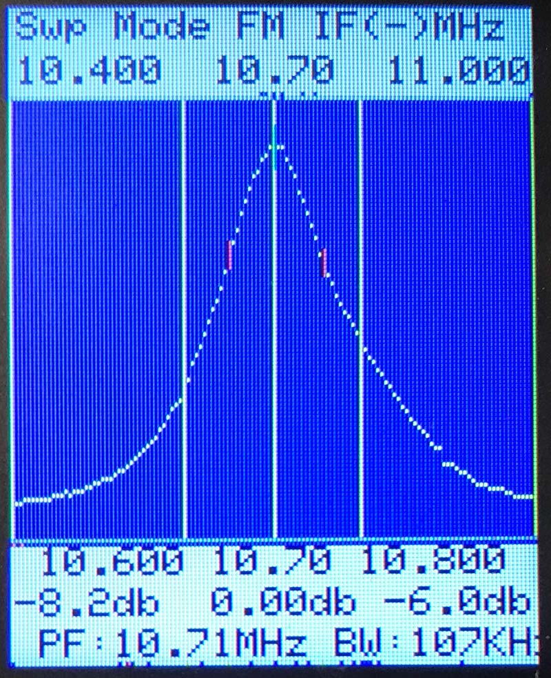
FIGURE 15. IF response after signal generator/voltmeter alignment.
Two options exist at this point: use the SS or DS mode. The choice is a matter of preference. For this example, the SS mode is used.
Step 3. Press the Sweep Mode button until the SS mode shows on the TFT display. With the radio powered off, reconnect the stabilizing capacitor Cs. Move the WSAB signal-in to point “C” in Figure 14. To start, adjust the Sweep Output Level and Sweep Input Gain to give a noise-free S-curve.
Figure 16A shows the response curve following signal generator/voltmeter alignment of the IF stages. Even though the IF response curve appeared normal, the S-curve turned out skewed and excessively non-linear between the carrier and -100 kHz marker. The poor-quality S-curve explained the Magnavox’s off station tuning and distorted sound when I used signal generator/voltmeter alignment at the outset.
Figure 16B shows the response curve after touch-up visual alignment with the WSAB.
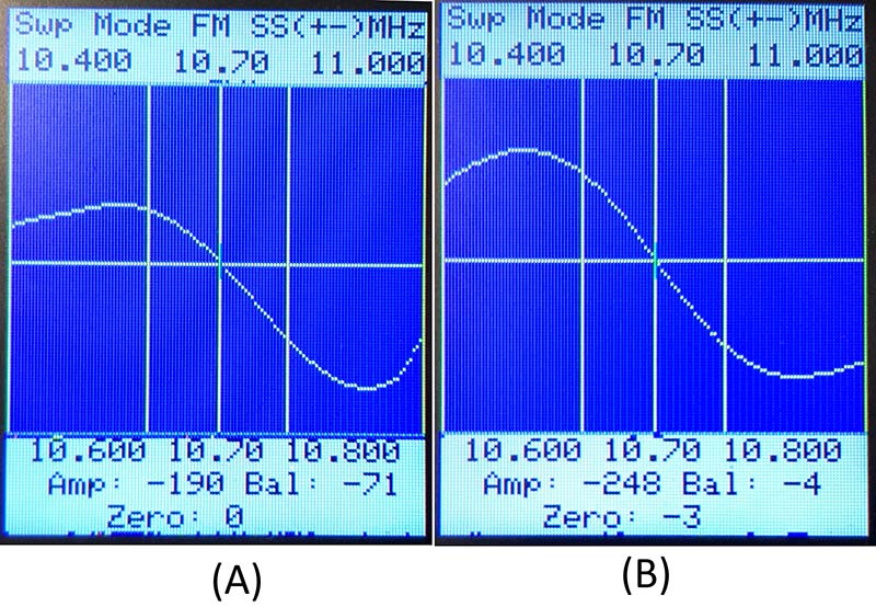
FIGURE 16. Ratio detector response curves: (A) after IF alignment; (B) after sweep touch-up.
Balance and symmetry are greatly improved. Most of the correction was the result of a small adjustment of the first IF transformer. In fact, experience with the WSAB has shown that the first IF transformer seems to be critical in getting a satisfactory S-curve shape!
Tracking alignment for the ratio detector is the same as for the discriminator.
A follow-up listening test of the Magnavox radio showed that the sweep alignment with the WSAB had corrected the issues associated with signal generator/voltmeter alignment. The time and effort expended on the project was well worth it!
Conclusion
While the AM sweep alignment was perhaps interesting, it could probably be done equally well with a signal generator and voltmeter. On the other hand, both FM sweep examples benefited significantly from visual alignment. The examples showed the quirks of using only a signal generator and voltmeter for FM alignment.
For the Zenith discriminator case, the initial voltmeter peaking produced a lopsided IF response curve. However, with the WSAB in sweep mode, that was soon put right. In the case of the Magnavox, the IF response after voltmeter alignment was good, but still the S-curve was ill formed. Again, the WSAB came to the rescue with the visual S-curve touch-up!
The WSAB is now a handy addition to my tube radio repair toolbox. Besides its essential role in FM alignment, there’s something reassuring about seeing the correct response curve when checking a repaired AM radio. While it may not have all the bells and whistles of commercial units, its low cost and convenience of use make it hard to beat! NV