Kids love to compete in all kinds of running games, so here’s an electronic project just for runners. The scoreboard I designed will record a runner’s elapsed time on a large LED seven-segment display. Starting the race is easy! Just press a button at the starting line; wait two seconds for a buzzer to go off; run 20+ yards; slap a numbered flag; and the scoreboard will show who won the race.
DESIGN INSPIRATION
My idea for this game came from watching my two grandsons (Johnny/Charlie) running around in the backyard. I really don’t remember having that much energy, endurance, or enthusiasm when I was their age. Anyhow, I thought I would design a running game where they could compete with other kids (friends/relatives).
Figure 1a shows the entire diagram for the running game as I envision it.
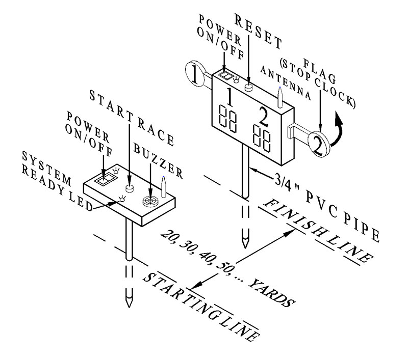
Figure 1a.
Figure 1b shows the finished project — fully assembled and ready to challenge any two runners.
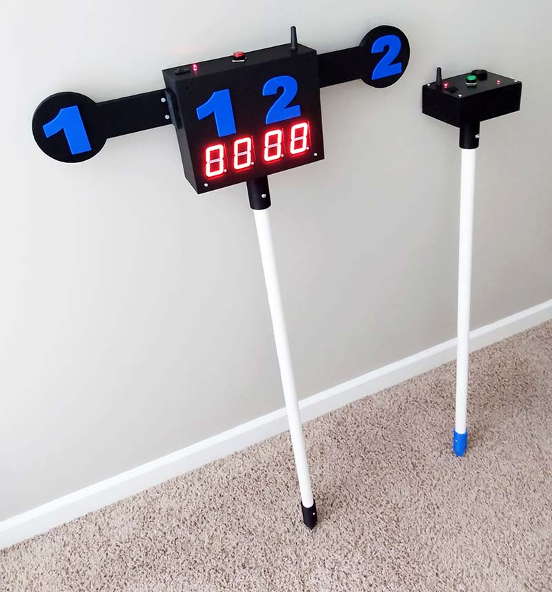
Figure 1b.
I should note here that except for the white PVC pipe and the digital readout, everything in the photo colored blue or black was created on a 3D printer.
HOW IT WORKS
Figure 2 is the schematic diagram for the ‘Starting Line’ circuit. Let’s break this simple circuit down step-by-step.
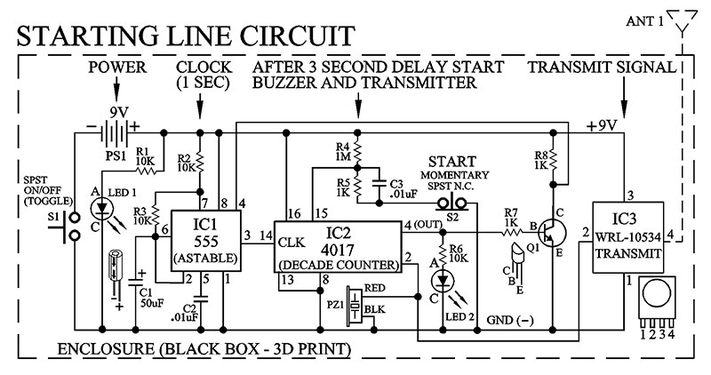
Figure 2.
First, the power button switch S1 supplies the circuit with nine volts. When pushed to the on state, it will light up LED1 to indicate there is power to the circuit.
Once power is applied to the circuit, pin 4 of IC2 (4017) will (after 10 seconds) switch to a high state (5V). This will turn on LED2 and transistor Q1 at the same time. Notice that with transistor Q1 (NPN) turned on, the collector will “see” a low. Since pin 4 (reset pin) of the IC1 (555) is wired to the collector of Q1, that low will disable the 555 — no pulses out of pin 3.
Now, when the Start switch S2 is pushed to the on state, the 4017 counter will reset (pin 15) to zero. This turns off pin 4 of the 4017. Consequently, the collector of Q1 and pin 4 of the 555 go high. Since the 555 is wired in an “astable” configuration, one second pulses will now flow out of pin 3. In turn, the pulses will clock the internal counter of the 4017 (pin 14), forcing the decade counter to count up from 1 to 10.
Once the count reaches the number 2, pin 2 will go high and turn on PZ1 (buzzer) and IC3 (transmitter) at the same time. They both will stay on for two seconds. Then, the 4017 counter will continue its count until it places a high on pin 4. Now, because of the way I configured (wired) the 4017, it will stop counting. This places a high on pin 4 and forces the collector of Q1 to go low, thereby turning off the 555 by way of reset pin 4.
In other words, when the buzzer PZ1 sounds off for two seconds and LED2 lights up, it means the entire circuit is in the ‘ready-to-go’ state of operation. So, runners should get set at the starting line!
To activate the circuit and begin the race, one runner must push the start button (S2). The sequence of circuit operations after switch S2 is pushed is just a repeat of the above description. After a runner hits the S2 switch, both runners will have two seconds before a piezoelectric buzzer (PZ1 - pin 2 4017) will sound the beginning of the race.
SCORE BOARD
Figure 3 is the schematic diagram for the scoreboard.
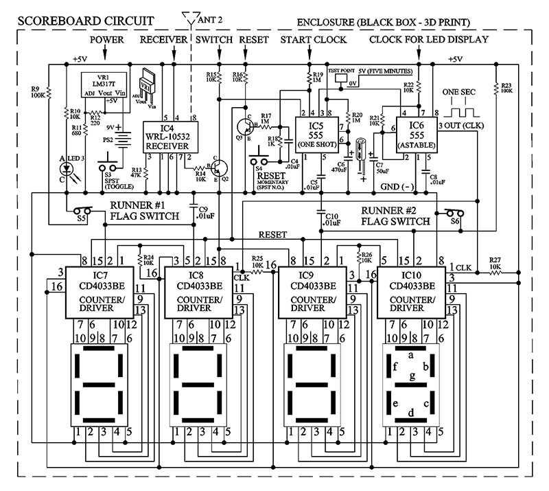
Figure 3.
If you ignore the display circuitry at the bottom half of the schematic, you’ll see the circuit is basically three ICs: the receiver (IC4); a one-shot 555 (IC5); and an astable 555 (IC6).
Unfortunately, because of the voltage limitation requirements for IC4 (receiver), a voltage regulator (LM317T) was needed to drop the 9V battery voltage down to 5V.
Here’s the simple version of how this circuit operates. Let’s assume a runner has pushed the start button and a signal (434 MHz carrier frequency) is being transmitted to the scoreboard circuit. Obviously, the receiver’s (IC4) job in this circuit is to pick up this small signal. It should be noted here that the signal is not modulated in any way in this circuit design. All we care about is if the signal is there or not.
If it is, turn on transistor Q2. Transistor Q2 was required at this point in order to switch on the 555 one-shot (IC5). This requires a high to low switching voltage across the transistor’s collector and at pin 2 of the 555. Now, the most important IC in this circuit is IC5 (555 one-shot). It has three jobs to perform.
The first job is to ignore the transmitted signal after it has been detected by IC4 (receiver). In other words, once the 555 one-shot is triggered by Q2, the 555 will “close the door” to all input signals (noise too) placed on pin 2 for the duration of the one-shot. It kind of acts like a ‘de-bounce’ circuit you would use on a mechanical switch.
The second job for IC5 is to turn on IC6 (555 astable). This is the clock signal needed to run the counter/driver ICs (4033) that generate the numbers on the four LED seven-segment displays. The third job for IC5 is to keep the clock signal (IC6) on for as long as possible (5 min) so the runners have time to reach the scoreboard, turn around, and look at their time on the scoreboard.
The two flags are connected to switches S5 and S6. Once a runner hits the flag with their hand, it will stop the clock feeding the counter/driver ICs (4033). Consequently, two of the four seven-segment LEDs will display the elapsed time for each runner.
Let’s discuss the seven-segment LED display circuitry. The counter/drivers IC7-IC10 (4033) control the LED displays. They work well, but only if you order the ‘common cathode’ type of LEDs. I made the mistake of ordering ‘common anode’ LEDs and then had the pleasure of watching the LED display count out the numbers with the ‘unlit’ segments of the LED (mistakes happen!).
Finally, after the race is over, the Reset switch S4 is what is used to reset all four LED displays back to zero. Just make sure the runners swing the two flags back into the closed position before hitting the reset button.
You’ve probably noticed the antenna in the schematic. I’ve found the range of the transmitter/receiver unit to be about 150 feet (50 yards).
CONSTRUCTION
There are five 3D printed parts in this project. Refer to Figure 4 (two spikes), Figure 5 (two flanges), Figure 6 (two flag #s), Figure 7 (‘Start’ and ‘Finish’ boxes), and Figure 8 (two flags).
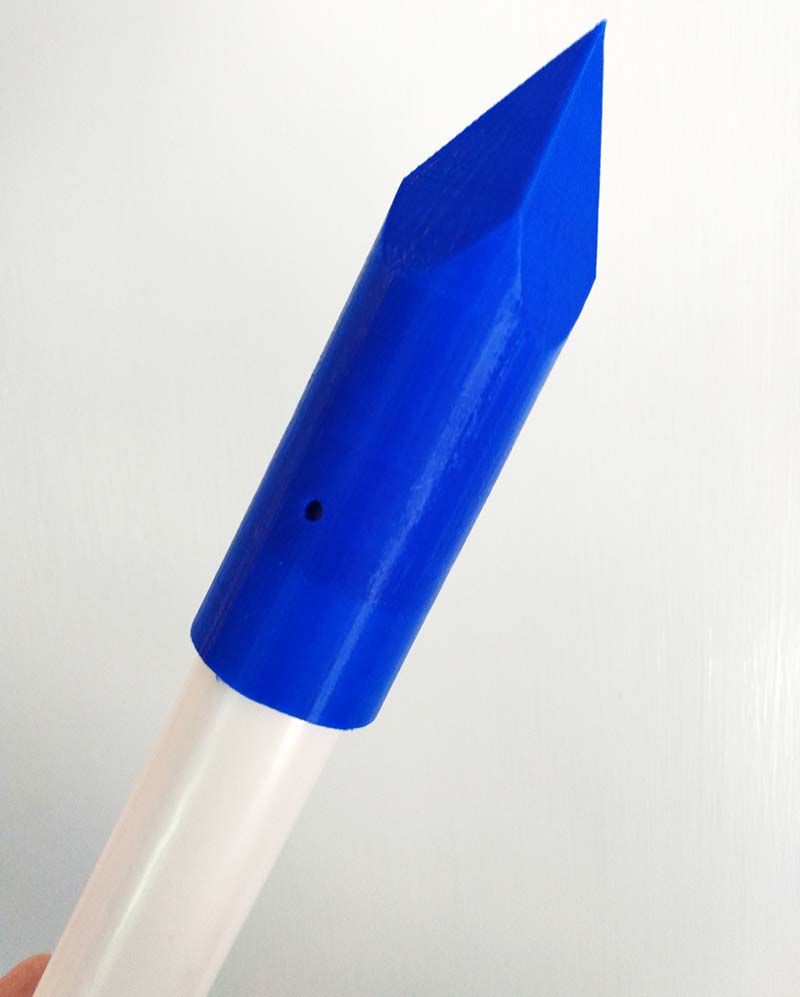
Figure 4.
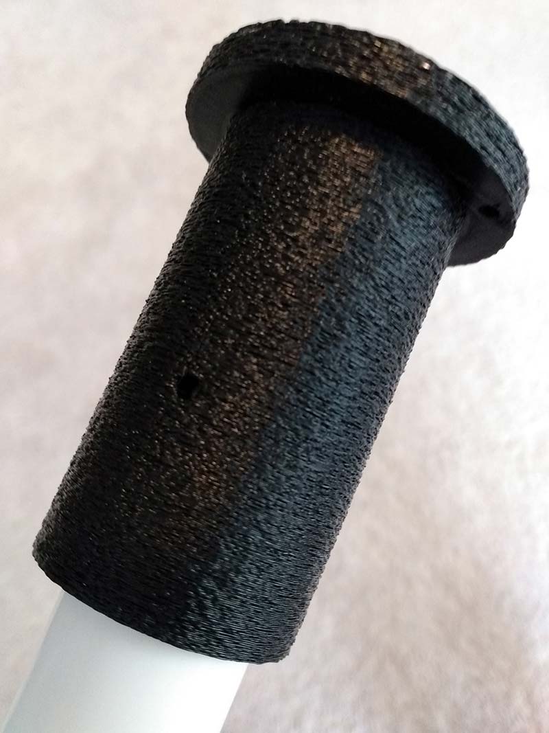
Figure 5.
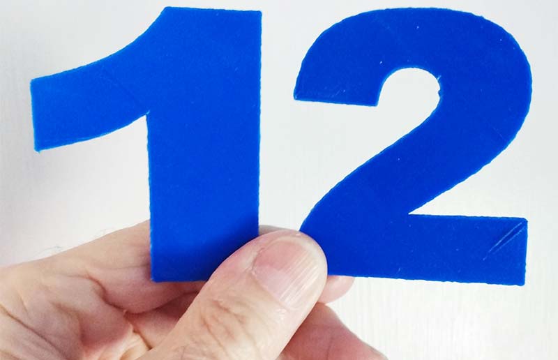
Figure 6.
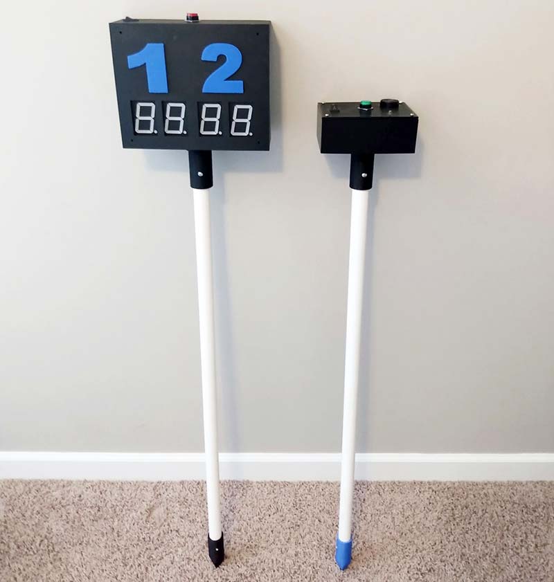
Figure 7.
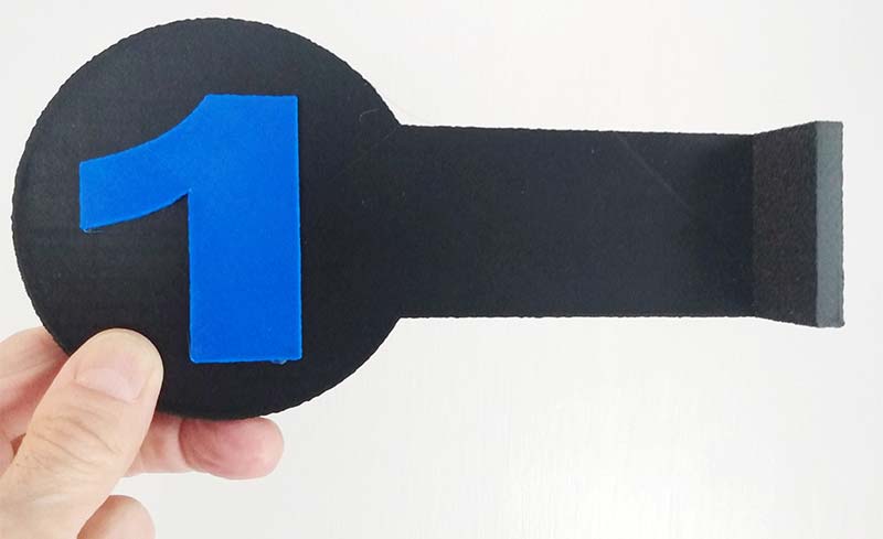
Figure 8.
If you’ve been thinking about getting a 3D printer, this project may be another good reason to buy one. If you don’t have one or can’t afford it right now, don’t worry! A friend, relative, or someone at school will probably have one. One alternative for getting parts made is to find a 3D printing service online.
On the other hand, if you have a few woodworking tools and some paint, there’s no reason why you can’t make all the parts out of wood.
TIPS
- Connecting the NO and NC switches in this project can be a little confusing. Figure 9 shows the correct wiring for switches S2, S4, S5, and S6.
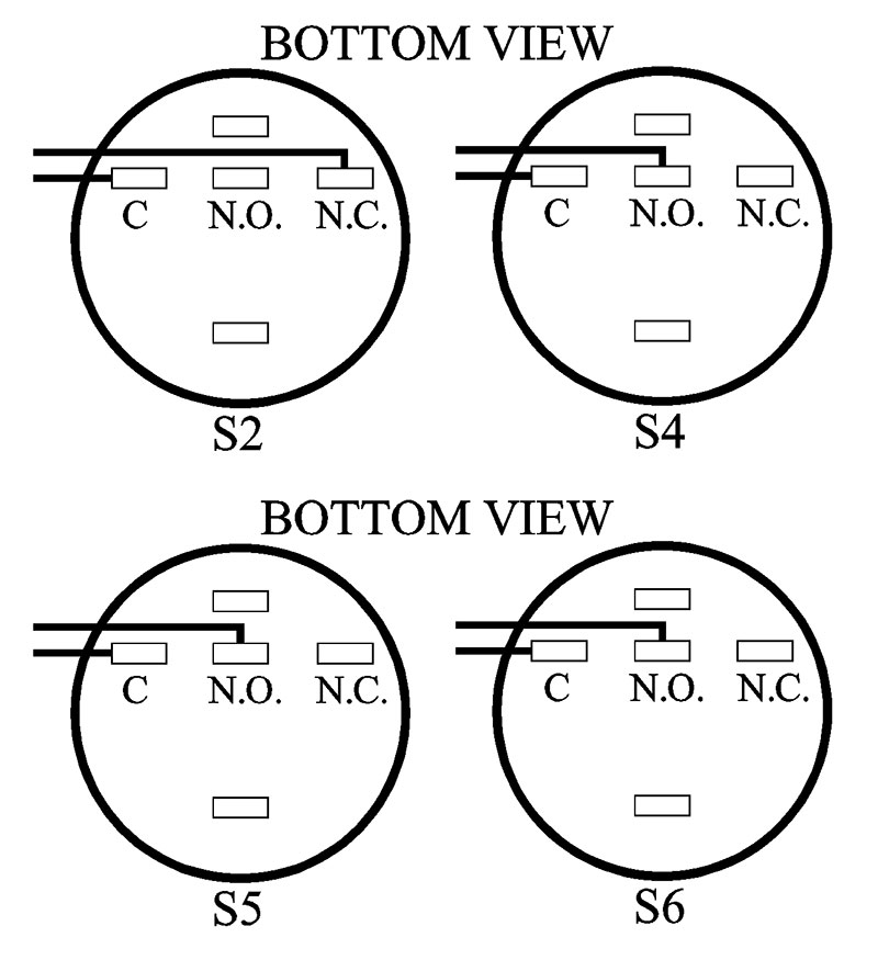
Figure 9.
- IMPORTANT! Before installing the Scoreboard PCB (printed circuit board) into the enclosure, you must label (magic marker/labeler) all the connection points for the switches, 9V power, the antenna, and the LED on the ‘solder’ side of the PCB (see Figure 10).
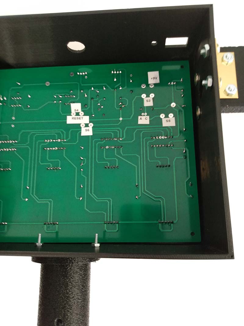
Figure 10.
- If you run a stripped piece of solid hookup wire through each hole, you’ll see where each point should be labeled and soldered.
- Mount the PCB (#4-40 x 3/4” machine screws) inside the enclosure before soldering or installing the switches, antenna, magnets, and LED. Otherwise, you might not have enough room to slide the PCB into the enclosure. Make sure to cut the hookup wire extra long for each connection. That way, if you need to troubleshoot the PCB, you can remove the PCB without de-soldering or cutting any wires.
- The orientation of the magnets (north/south poles) is critical during the scoreboard assembly. So, before you hot/super glue the magnets into place, mark the top or bottom surface of each magnet with the correct pole letter (N or S).
- Note that all the magnets used in this project must be glued flush to the outer surface of the enclosure and flags. Otherwise, the flags will not trigger switches S5 and S6 when the runner slaps the flag.
- Also, be aware that the magnets are very strong and brittle. So, during assembly, separate the magnets on your workbench by at least 10 inches.
- The 9V battery for the starting line circuit can be attached to the PCB with double-sided tape. The six AA battery holder (see the Parts List) for the scoreboard can be attached to the bottom of the enclosure in the same way.
- When troubleshooting the circuit boards, always start the hunt with a new set of batteries. Otherwise, you’ll waste time chasing a ghost that isn’t there.
- If the scoreboard is not working, make sure the two switches S5 and S6 are activated (pushed in) when the two flags are in the normal position out to the side of the scoreboard.
- Set the game up by placing a small piece of wood (2” x 4”) on top of the PVC pipe and hammer the pipe into the ground. If the ground is dry and hard, dump a small bucket of water over the insertion point a few minutes before you pound the PVC pipe into the ground.
- Once the PVC pipe is set up, place the scoreboard unit (flange attached) on top of the pipe. Finally, secure the flange to the pipe with a #8 x 32 x 1-3/4” machine screw and nut (#8-32).
- If rain is in the forecast, you can leave the running game outside by covering both black boxes with 13 gallon kitchen garbage bags.
- Always power-up the starting line circuit (switch S1) before switching the scoreboard circuit on (switch S3). The reason is that during the power-up sequence, the starting line circuit will send out a short 434 MHz pulse. This untimely signal will start up the scoreboard before the race even begins. To avoid having to reset the scoreboard every time you power up the game, switch S1 on first, wait 10 seconds, then switch on S3.
- After the running contest, remember to swing both flags back into their normal starting positon (magnetic connection) before resetting (S4) the LED display back to zero.
- It wouldn’t hurt to instruct all the runners not to slap the numbered flags too hard. The flags just need to be slapped hard enough to swing backwards, thereby releasing the magnetic connection.
That’s all there is to building a wireless running game. Now, lace up your running shoes and see how low of a score you can get on the scoreboard.
If you’re up there in the years, please try not to cry in front of the children when you see a high score. It sends the wrong message. NV
Parts List
| QTY |
ITEM |
DESCRIPTION |
PART NUMBER |
SOURCE |
| 14 |
R1-R3, R6, R10, R14-R16, R21, R22, R24-R27 |
Resistor, 10K, 5%, 1/4W, Through Hole |
660-CF1/4C 103J |
MOUSER |
| 2 |
R9, R23 |
Resistor, 100K, 5%, 1/4W, Through Hole |
660-CF1/4CU104J |
MOUSER |
| 4 |
R5, R7, R8, R18 |
Resistor, 1K, 5%, 1/4W, Through Hole |
660-CF1/4C102J |
MOUSER |
| 1 |
R11 |
Resistor, 680 ohm, 5%, 1/4W, Through Hole |
660-CF1/4C 681J |
MOUSER |
| 1 |
R12 |
Resistor, 220 ohm, 5%, 1/4W, Through Hole |
660-CF1/4C 221J |
MOUSER |
| 1 |
R13 |
Resistor, 47K, 5%, 1/4W, Through Hole |
660-CF1/4C 473J |
MOUSER |
| 4 |
R4, R17, R19, R20 |
Resistor, 1M, 5%, 1/4W, Through Hole |
660-CF1/4C105J |
MOUSER |
| 2 |
C1, C7 |
Capacitor, 50 µF, Electrolytic, 450V, 20% |
140-RXC500M2WBK-1340 |
MOUSER |
| 1 |
C6 |
Capacitor, 470 µF, Electrolytic |
EEU-FR1E471B |
MOUSER |
| 7 |
C2, C3, C4, C5, C8, C9, C10 |
Capacitor, .01 µF, Ceramic |
594D103Z25Z5VF63L6R |
MOUSER |
| 3 |
Q1-Q3 |
Transistor, 2N2222A, NPN |
610-PN2222A |
MOUSER |
| 1 |
IC2 |
Decade Counter, 4017, 16-pin DIP |
595-CD4017BE |
MOUSER |
| 4 |
IC7-IC10 |
Counter/Dividers, CD4033BE, 16-pin DIP, CMOS |
595-CD4033BE |
MOUSER |
| 5 |
IC2, IC7-IC10 |
IC Socket, 16-pin DIP, 20.32 mm long x 10 mm wide x 4.8 mm in height |
571-1-2199298-4 |
MOUSER |
| 3 |
IC1, IC5, IC6 |
Timer, NE555P, Eight-Pin |
595-NE555P |
MOUSER |
| 3 |
IC1, IC5, IC6 |
IC Socket, Eight-Position |
575-144308 |
MOUSER |
| 1 |
IC3 |
Transmitter, 434 MHz |
474-WRL-10534 |
MOUSER |
| 1 |
IC4 |
Receiver, 434 MHz |
474-WRL-10532 |
MOUSER |
| 4 |
DS1-4 |
LED Display, Seven-Segment, 1.5” x 2.2”, Common Cathode |
FJS18101AH |
ALIEXPRESS |
| 1 |
VR1 |
Voltage Regulator, 5V, LM317T |
511-LM317T |
MOUSER |
| 3 |
LED1-3 |
LED, Red 640 nm, Through Hole, 5 mm dia., 8.7 mm height, Clear Dome (Ultra-Bright) |
604-WP1503SRC/J4 |
MOUSER |
| 2 |
S1, S3 |
Switch, QTEATAK On/Off Boat Rocker Switch, 2-pin, SPST, 21 mm x 15 mm, 12V |
n/a |
AMAZON |
| 4 |
S2, S4, S5, S6 |
Switch, SPDT, Baomain Momentary Pushbutton Switch, NO / NC Contacts, Five-Pin, 16 mm diameter Thread, 24V |
n/a |
AMAZON |
| 1 |
PZ1 |
Piezoelectric Buzzer, 3-24 VDC, Continuous Beep |
OD2017101303UP |
MOUSER |
| 2 |
BATTERY SNAPS |
Battery Snaps & Contacts, 9V, 26 AWG |
121-0526/I-GR |
MOUSER |
| 1 |
BATTERY HOLDER |
Battery Holder for Six AA Batteries, w/9V Snaps |
n/a |
AMAZON |
| 1 |
PS1 |
9V Battery |
n/a |
AMAZON |
| 1 |
PS2 |
Six AA Batteries |
n/a |
AMAZON |
| 1 |
HOOK-UP WIRE |
Solid Hook-up Wire, 22G, 100 ft by EX Electronix |
n/a |
AMAZON |
| 2 |
HINGE |
Polished Brass Finish Hinge, 1-1/2” x 1-1/4”, Hole Spacing 1.00”, Non-Removeable Pin |
#0311946 |
LOWES |
| 12 |
SCREW |
Wood Screw, #4 x 1/2”, Round Slotted |
#490038 |
LOWES |
| 4 |
SCREW |
Machine Screw, #4 - 40 x 3/4”, Round Combo |
#491276 |
LOWES |
| 4 |
SCREW |
Machine Screw, #8 - 32 x 1-3/4”, Round Combo |
#491293 |
LOWES |
| 8 |
SCREW |
Machine Screw, #8 - 32 x 1/2”, Flat Phillips |
#490415 |
LOWES |
| 4 |
MAGNET |
Neodymium, 12 mm O.D. x 4 mm I.D. with Countersunk Hole: 4 mm, 4.5 mm in height |
n/a |
EBAY |
| 1 |
START PCB |
PCB, Two-Layer, 2 oz Copper, Plated Through Holes |
n/a |
allpcb.com |
| |
|
|
n/a |
jlcpcb.com |
| 1 |
FINISH PCB |
PCB, Two-Layer, 2 oz Copper, Plated Through Holes |
n/a |
allpcb.com |
| |
|
L = 8.00” x W = 6.50” |
n/a |
jlcpcb.com |
| 2 |
PVC PIPE |
3/4” dia. (I.D.), 1120, SCH40, PR480 PSI, 72” long |
n/a |
LOWES |
| 2 |
ANT 1, ANT 2 |
Antenna, Length 1.988”, Mounting Hole 21/64” |
ANT-433-PW-LP-ND |
DIGI-KEY |