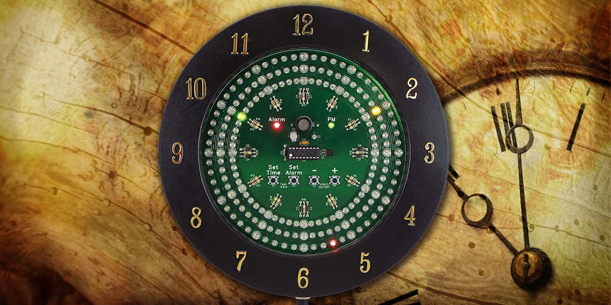
Several years ago, I read about a technique called Charlieplexing where you can control a large number of LEDs individually with a relatively small number of I/O lines. I immediately thought that a good use of this technique would be to make a clock. It would have three circles of 60 LEDs each. The outer circle of LEDs would be for representing seconds, the middle circle for minutes, and the inner circle for hours. Although only 12 LEDs would be needed to display hours, I thought it would be more symmetrical if I used 60 and advanced it every 12 minutes. I had envisioned using both T1 (3 mm) and T1-3/4 (5 mm) LEDs; the larger LEDs would be used every fifth position at each hour mark.
The clock never became much more than an idea in the back of my mind until I decided to make it for my Senior Project to complete my Electrical Engineering degree.
Decisions, Decisions
I wanted to use a microcontroller with the lowest pin count possible. I figured I could drive the LEDs with 14 I/O pins using Charlieplexing (more on that later). Two more I/O pins would be used to read two pushbuttons used for setting the clock.
I had already picked out the microcontroller that I wanted to use. I had been playing around with Microchip products for a number of years, so I chose the PIC16F627A. It was an 18-pin controller with 16 I/O lines — the exact number of I/O lines that I needed.
However, my professor insisted I add an alarm feature. Now I needed to add a buzzer for the alarm and probably a couple more pushbuttons to set it. Plus, one more LED to indicate when the alarm was turned on would be necessary.
I decided to include another LED for a PM indicator, so an alarm that was set for say, 6:00 AM wouldn’t sound at 6:00 PM. I then considered that I would be running the microcontroller with its internal oscillator that probably wasn’t all that stable; the clock wouldn’t keep accurate time. It would be much more precise to monitor the 60 Hz from the electric utility for the time base (refer to the sidebar). How many more I/O pins would now be necessary?
Although Microchip has plenty of microcontrollers that have more than enough I/O pins for this project, I really didn’t want to increase the pin count of the controller! Was it actually possible to drive 182 LEDs and a buzzer, and monitor four pushbuttons and the line frequency with only 16 I/O pins? Or, was my pride going to get me into trouble (why couldn’t I just add a few pins)?
The buzzer would definitely need its own dedicated I/O line. The LEDs would require 14 I/O pins. That would leave only one pin to read the pushbuttons and monitor the line frequency.
A couple of ideas occurred to me. I had the vague notion that I could connect the pushbuttons and the 60 Hz signal through a resistor network to the I/O pin. An analog input to detect changes in voltage could be used to interpret the button combination currently being pressed, and at the same time, monitor the 60 Hz line. The other thought was to use four of the LED I/O pins to strobe the buttons, and using diodes for isolation, connect the buttons and 60 Hz together into the I/O pin.
A cursory look at the datasheet for the PIC16F627A showed that it had all the necessary features to run the clock. It had 16 I/O lines with high current capability for direct LED drive, an internal oscillator, and analog input capability. If the 1K bytes of program memory wasn’t enough, either the PIC16F628A or PIC16F648A could be used, which have 2K or 4K bytes of program memory, respectively. Otherwise, they’re identical to the PIC16F627A.
Driving 182 LEDs with Only 14 I/O Pins
Complementary LED drive — also known as Charlieplexing — allows a large number of LEDs to be controlled with a relatively small number of I/O pins as previously mentioned. Charlieplexing is named after Charlie Allen of Maxim Integrated.
He used this technique to create LED driver ICs for Maxim in the 1990s (www.maximintegrated.com/en/app-notes/index.mvp/id/1880). The idea behind Charlieplexing is simple: Given every possible combination of two I/O ports, connect two LEDs between them, with the two LEDs in parallel and in opposite directions.
Another way to look at Charlieplexing is to consider a standard 4x4 matrix of LEDs (Figure 1).
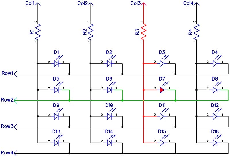
FIGURE 1. Standard 4x4 LED matrix.
There are four rows and four columns, requiring a total of eight I/O lines to control 16 LEDs. You’ll notice that each column has a current-limiting resistor. To light an LED, you would apply +5V to a column and ground to a row. The LED at that intersection would light. For example, to light D7, you would apply +5V to column 3 (shown in red) and apply ground to row 2 (shown in green). The result is that D7 illuminates.
Now, suppose that you remove the diagonal LEDs, and at these intersections, you connect the rows to the columns. Now, the rows will no longer be needed and can be removed. The result is 12 LEDs connected to just four I/O lines (Figure 2). This is Charlieplexing.
To light an LED, you would apply +5V to a column as before, but ground would be applied to a different column. For example, to light D7, you would apply +5V to column 3 and ground to column 2. The result is that only D7 lights. In this configuration, current flows through two resistors: R3 and R2. The LED will have between 2V and 2.4V across it, depending on the LED and its characteristics. Therefore, R2 and R3 will have a voltage drop of between 1.3V and 1.5V across them.
Although D10 has power and ground applied, it’s reversed-biased and will not light. There are additional forward-biased current paths; for example, through D3 and D5. However, there are at least two LEDs in any such path. Since D7 maintains at most a 2.4V drop, no other LED in the matrix will have more than 1.2V across it. This voltage is insufficient to break through the PN junction; therefore, no current will flow, and no other LED will light.
It’s important that all other columns are floating; that is, they are not connected to +5V or ground. This is accomplished by placing these I/O lines of the microcontroller into their input state, thus creating a high-impedance condition so they aren’t drawing or sourcing any current.
With a given number of I/O lines (N), how can the number of LEDs that can be controlled be calculated? Figure 2 gives a visual representation of the answer.
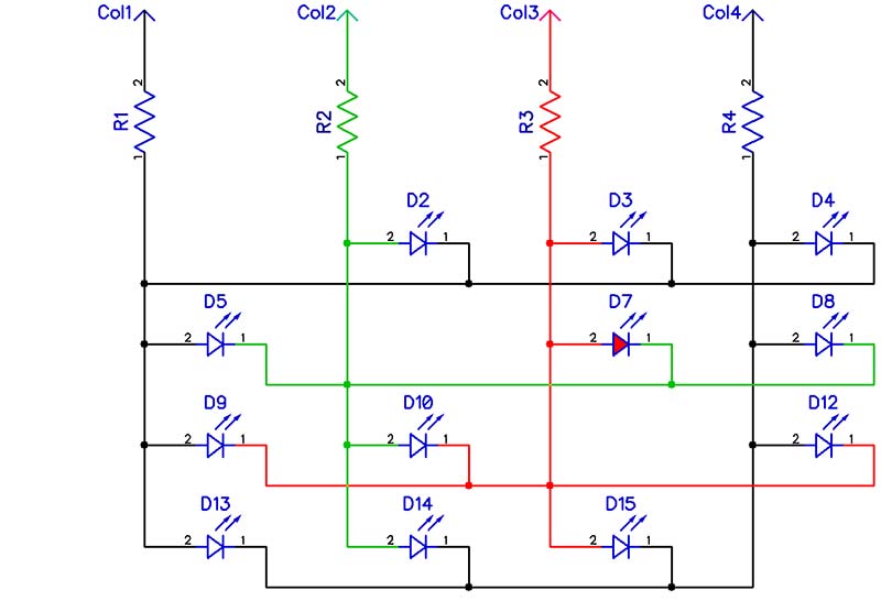
FIGURE 2. Four-line Charlieplexed matrix.
The number of LEDs that can be Charlieplexed is N (number of rows) times N (number of columns) minus N (number of diagonal LEDs removed). For this example, the number of LEDs four I/O pins can control can be calculated by:
LEDs = (N•N) - N = (4•4) - 4 = 12
If the matrix is constructed using 14 I/O pins, then we have:
LEDs = (N•N) - N = (14•14) - 14 = 182
That happens to be exactly the number of LEDs we need for the LED clock!
Only one LED can be lit at a time in a Charlieplex matrix. To achieve the illusion of up to five LEDs being on at the same time, the LEDs are lit one at a time in rapid sequence — fast enough that the human eye cannot distinguish any flickering. I decided to use high-intensity LEDs since each one will only be on about 20% of the time.
I decided to build a smaller 12 LED circuit on a breadboard to test the concept and to begin development of the software. The biggest challenge, however, was going to be figuring out how to read multiple pushbuttons and the 60 Hz signal using only one I/O pin.
Using 60 Hz for Timekeeping
A question I'm often asked is, "How accurate is the 60 Hz from the electric utility?" The simple answer is that it is surprisingly accurate.
In the 1920s, Laurens Hammond invented an electric clock driven by a synchronous AC motor. It kept time using a motor that was in sync with the 60 Hz frequency generated by the utility companies. He gave away hundreds of these clocks to power stations as an incentive to maintain a steady frequency which allowed his inexpensive clock to be used anywhere in North America.
Hammond went on to help create the Hammond Organ which used a synchronous AC motor to drive a "tone wheel" generator which created perfect pitches for the instrument.
Just about everything that has a clock and plugs into the wall uses the 60 Hz for synchronization. I have an inexpensive alarm clock on my nightstand that if power is lost, the display goes out, but it keeps time on battery backup. While plugged in, it keeps excellent time. If I unplug it and take it on a trip, when I get to my destination a few hours later, the clock has invariably lost or gained several minutes.
In 2010, I made a countdown timer that utilized the 60 Hz from the electric utility as a time base. I used a clock that kept in sync with the atomic clock in Boulder, CO to test my timer's accuracy. At that time, I noticed that the timer would drift 5 or 10 seconds throughout the day. I never saw it more than 10 seconds off, and it always came back to the correct time around the same time each day.
Since then, the utility companies have gotten more lax concerning the accuracy of the 60 Hz generated. In order to maintain accuracy, an adjustment is made to the frequency — known as a Time Error Correction (TEC). The more often TECs are made, the more accurate clocks basing their time on it will be. Power utilities used to ensure that the total number of cycles in 24 hours was correct using daily TECs. Now, a TEC is made when the cumulative error exceeds a certain threshold. As a result, the frequency is not as accurate as it used to be, but is still very accurate.
I've been running my countdown timer as well as the analog-style LED clock, periodically checking them against each other and the atomic clock. Over a year later, the countdown timer and the LED clock are in perfect sync with each other (as would be expected), and both are 24 seconds ahead of the atomic clock. The most my timer and clock were ever off from atomic time was 52 seconds. I think that any clock that is within a minute over the course of a year is very accurate.
Unfortunately, there are efforts to remove the requirements for TECs in North America. It was estimated that if TECs had not been implemented in 2016, clocks using the frequency for their time base would have lost about seven minutes over the course of the year. Still not too bad; definitely much better than the clock in my car!
Special Note:
Please keep in mind that wherever I reference 60 Hz, the concept would work equally as well in much of the world where the electric utility runs at 50 Hz. A simple change in the code would accommodate 50 Hz.
A Closer Look at the PIC16F627A Microcontroller
The PIC16F627A has 16 I/O pins alright, but only 14 of them could source and sink current. One pin (RA4) could only sink current and the remaining pin (RA5) was an input only. The reason for the limited capability for RA4 and RA5 was that they doubled as programming pins for the chip. This allows the programmer to be able to manipulate these pins without interference from a running program.
Since all the pins in the Charlieplex matrix must be able to source and sink current, the 14 I/O pins that were capable of both had to be used for the LEDs. The I/O line that could only sink current would work for driving the buzzer. This left the input-only pin to read the switches and 60 Hz. So far, so good.
However, RA5 —the input-only pin — had no analog capability; it could not be connected to the chip’s internal comparator. Not only was RA5 just an input line, it was a digital-only input line. Therefore, my first idea of using a resistor network to feed varying voltages to the input pin would not work. However, a second idea of strobing the buttons with four of the LED lines just might.
The Test Circuit
The finished test circuit can be seen in Figure 3.
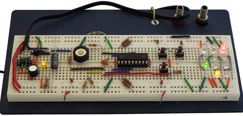
FIGURE 3. Test circuit on breadboard.
I used a wall wart with a nine volt AC output to power the circuit. It connects to J1 and J2 of the schematic shown in Figure 4.
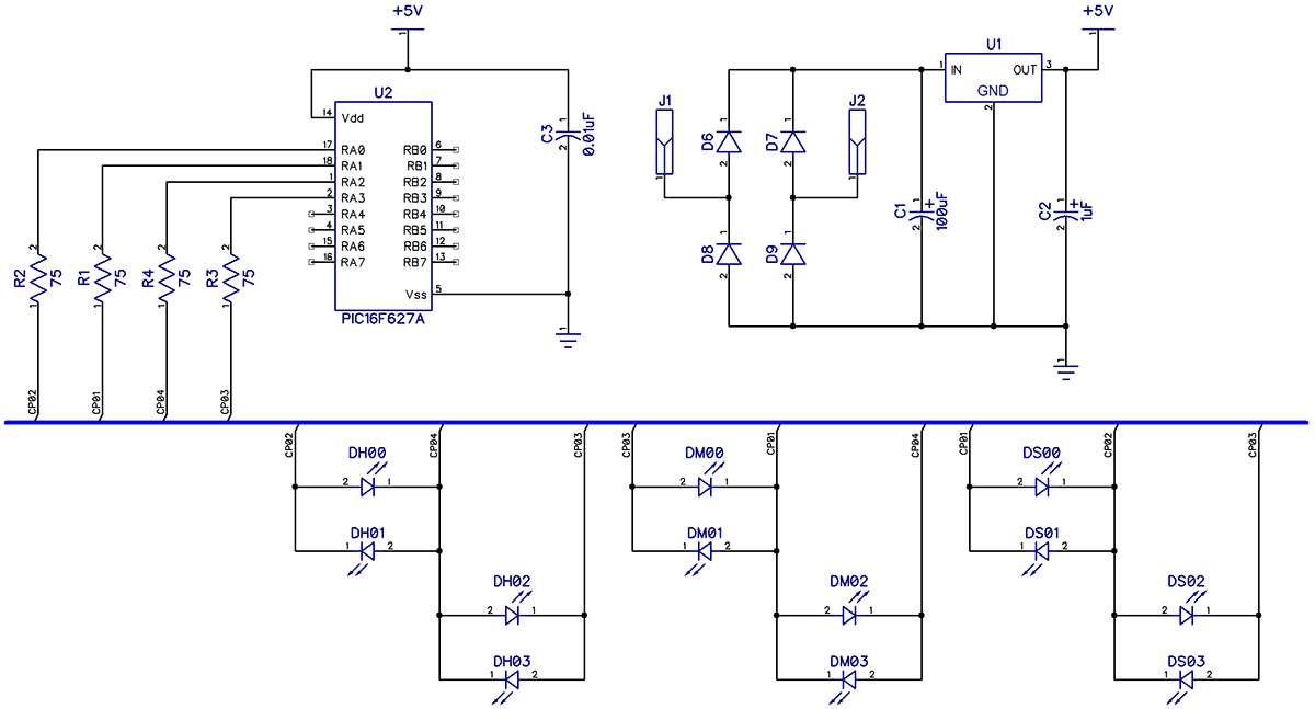
FIGURE 4. Test circuit schematic with power supply, microcontroller, and LEDs.
I built a bridge rectifier (D5-D8), followed by a +5V regulator (U1), and then the appropriate filter capacitors (C1-C2) to create the power supply. The 12-LED Charlieplex matrix (DH00-DH03, DM00-DM03, DS00-DS03) was then wired up to four of the I/O pins through the appropriate current-limiting resistors (R1-R4). The nodes that are after the current-limiting resistors are CP01-CP04.
The test code had the microcontroller running a sequence on these 12 LEDs — similar to what would be used for the finished clock, with each LED lit 20% of the time. I discovered a couple of things.
First, Charlieplexing LEDs works remarkably well. I expected to see a tiny amount of light coming from the LEDs that were off since there would be a tiny amount of current flowing through them anyway. Even in a pitch-dark room with the lit LEDs completely covered, I could not detect any light coming from the unlit LEDs.
Second, I was surprised to find that for the proper balance in apparent brightness of the LEDs, the T1-3/4 (5 mm) LEDs had to be rated more than two times as luminous as the T1 (3 mm) LEDs. It made sense when I calculated that the larger LEDs have about 2.8 times the cross-sectional area as the smaller ones. It turned out that using small LEDs with luminance ranging from 250 to 310 mcd and large LEDs with luminance ranging from 680 to 700 mcd worked very well.
Let’s Make Some Noise
Next, I hooked up a buzzer (BZ1) between an I/O line and +5V (Figure 5). I added 150Ω (R9) in series for some current limiting, as the buzzer was designed for three-volt operation. I later determined that 33Ω was sufficient and ended up using two 75W resistors in parallel for an equivalent resistance of 37.5Ω.
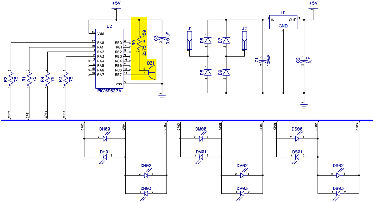
FIGURE 5. Test circuit schematic with buzzer added.
It was fairly trivial to get it to buzz near its resonance frequency of 2 kHz. I had already set up an interrupt to trigger every 256 μs (I’ll go over the software in Part 2). All I had to do was pull the output line down on one interrupt, then release it on the next interrupt; this created a square wave with a period of 512 μs, or 1,953 Hz.
60 Hz Input
I had an idea to connect each pushbutton to a line in the LED matrix. The other side of the buttons and the 60 Hz signal would be connected together — adding diodes in series for isolation — to the input-only pin (RA5). A pull-up resistor to +5V would be added to the input line.
To read the switches, I would pull down the line to one switch (while all other LED lines were floating in a high-impedance state) and read the result on RA5.
One problem with this circuit was that while a button was held down, the pull-up resistor would feed voltage into the LED matrix. Even with a fairly high value for the pull-up resistor, it would cause random LEDs to glow.
The other issue I quickly realized was that when the microcontroller was holding down one of the switch lines, current would feed through the LEDs to the other switch lines — effectively holding them partially down.
The other lines would not drop to ground, but would be held down to about two volts or so. A digital input would not be able to reliably distinguish the difference; therefore, the software would not be able to tell which switches were activated. Holding one switch line low while holding the other three high would prevent this problem, but would be unacceptable as that would result in lighting LEDs.
It became apparent that an analog pin for the button input would need to be used. Therefore, I decided to dedicate RA5 to monitor the 60 Hz line. Since the AC line swings well beyond the voltage range of the input pin, I added a current-limiting resistor (R5).
Input pin RA5 has an internal diode to clamp the input to ground, but there is no internal diode to clamp the input to +5V. This is because the chip is put into program mode by raising this pin higher than five volts. I didn’t want the chip to go into program mode, so I added D5 to clamp the input to +5V (Figure 6).
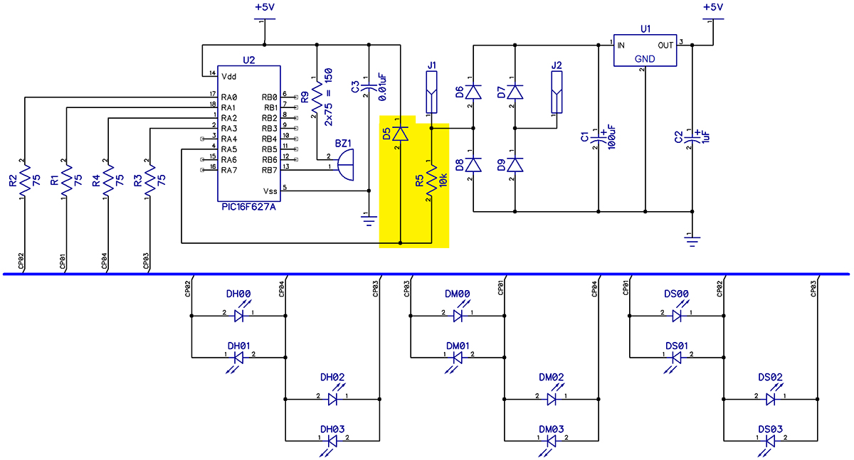
FIGURE 6. Test circuit schematic with AC input added.
Getting Testy
I had the test circuit working as I had envisioned. It was running a counting sequence similar to what the final clock would run. It was responding to the buttons and was able to sound the buzzer. The only problem was that some of the LEDs that were supposed to be off were faintly glowing.
I removed the button circuit, thinking that was the problem, but the LEDs continued to glow. I removed the microcontroller and manually turned on various LEDs and the glow was gone. I figured that the glow was probably caused by either a programming error or stray capacitance in the breadboard.
Even if I couldn’t eliminate the glow, it was dim enough to be hardly noticeable. On to the final circuit!
Buttons
I needed to come up with a way to read the switches with an analog pin. Of course, all the analog input pins were being used to drive the LED matrix. No matter what I tried, either unwanted LEDs would light up, or the status of the switches could not be read. Just when I was about to give in to using a microcontroller with more I/O pins, I came across the solution!
A button circuit was connected to nodes CP01-CP04, which are after the LED current-limiting resistors R1-R4; refer to Figure 7.
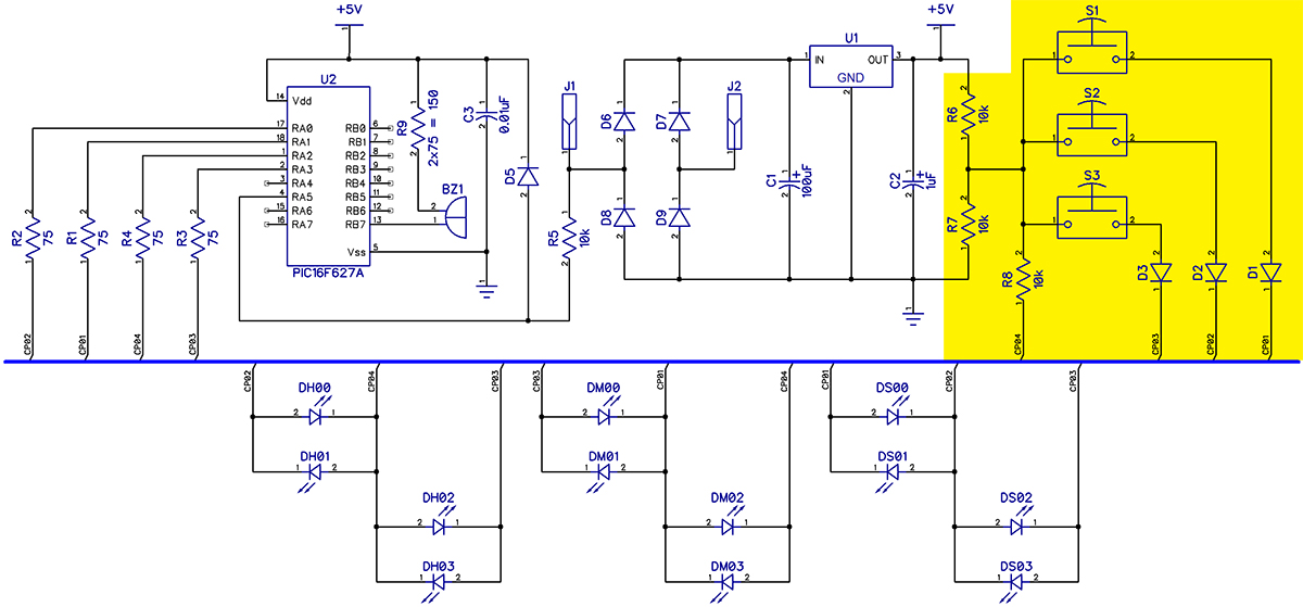
FIGURE 7. Test circuit schematic with pushbuttons added.
A voltage divider was created with R6 and R7 that provides 2.5 volts that’s applied to CP04 via resistor R8. Buttons S1-S3 were connected to the output of the voltage divider. The other side of the buttons were connected to CP01-CP03 through diodes (D1-D3). These diodes keep CP01-CP03 isolated from each other when more than one button is pressed at the same time.
How the Circuit Works
Recall that while the microcontroller is driving an LED, there is at least a 1.3 volt drop across each of the two current-limiting resistors involved. Therefore, the current-sinking node would be no less than 1.3 volts and the current-sourcing node would be no more than 3.7 volts. If CP04 is not driving an LED, it’s kept in a high impedance state.
Therefore, the voltage divider output of 2.5 volts appears on CP04. This would place no more than 1.2 volts (3.7V-2.5V or 2.5V-1.3V) across any affected LED in the matrix, which is not enough voltage to turn it on.
Let’s suppose that S2 is pressed while CP02 is sinking current. The voltage divider output drops to no less than 2.0V, due to the 0.7V drop across D2. If CP04 is in high-impedance mode, this would place 2.0 volts into the Charlieplex circuit at that point. The sourcing Charlieplexed line could produce as much as a 1.7V drop across an LED (3.7V-2.0V), while the sinking line could produce as much as a 0.7V drop (2.0V-1.3V) — neither of which is sufficient to turn an LED on.
I found that when CP04 is sourcing current into the matrix, it causes the output of the voltage divider to rise from 2.5 volts to 2.9 volts. Suppose button S2 is being pressed at this time. Current could flow through that button and D2, into the matrix at CP02. Due to the 0.7 volt drop across D2, no more than a 2.2V current source would be placed into the matrix. This would place at most 0.9 volts across any LED — again, far below what is required to turn it on.
When CP04 is used to sink current in the LED matrix, the output of the voltage divider drops to about 2.1 volts. If, for example, button S2 is pressed, D2 prevents this voltage from providing a current sink into the matrix. A current source of 1.4 volts appears at CP02, just 0.1 volts above the line being driven low — definitely not enough to turn on an LED.
Therefore, no matter which LED is lit and no matter what buttons are pressed, the button circuit cannot cause any other LED in the matrix to light.
To detect the state of a button, the I/O line to that button is brought low, while all remaining I/O lines in the LED matrix are left in the high-impedance input state.
For example, to read S1, CP01 (which is connected to S1 via D1) would be set to low output. If the button is not pressed, 2.5V from the voltage divider would be fed through R8 into CP04. The LED, DM03 which is connected with its cathode on CP01 and its anode on CP04, will cause the voltage divider output to drop to the operating voltage of that LED — between 2.0V and 2.4V.
This voltage appears at the microcontroller at RA2 via R4. The current going through DM03 is greatly limited by R6 and R8, and since the button is read in a few microseconds, not enough current will flow through the LED to make it appear to illuminate to the human eye.
If S1 is pressed, current through D1 will force the output of the voltage divider to drop to 0.7 volts. That voltage is passed through R8 and R4 and appears on RA2. So, to determine if a button is being pressed, the microcontroller brings that button’s I/O line low and then looks at the resulting voltage on RA2.
If it’s around 0.7 volts, then the button is being pressed; if it’s two or more volts, then it is not. Each button is read one at a time by bringing that button’s line low while leaving the other Charlieplexed lines in their high-impedance state.
The microcontroller has a built-in comparator and a built-in programmable voltage reference that can be used to detect the small voltage change. I programmed the microcontroller so that RA2 is connected to the inverting (-) input of the comparator, and the noninverting (+) input is connected to the programmable voltage reference. I set the voltage reference to 1.042V.
If the button is pressed, the voltage at the I/O pin is 0.7V and the comparator’s output goes high. If the button is not pressed, the input voltage is at least 2.0V and the comparator’s output goes low. The output of the comparator is read as a 1 or 0 by the microcontroller.
Time’s Up
That wraps up this first part. In Part 2, we’ll finish the circuit, make the printed circuit board, build the clock, and take a look at how the software works. In the meantime, you can find the software source files with the article downloads if you want to take a peek. See you next time! NV
A kit is available through the Nuts & Volts webstore at https://store.nutsvolts.com/project-kits/sku15871.
Downloads
What’s in the zip?
PCB Files
Code
What’s in the zip?
Assembly Manual