The last time I had my hearing aids serviced, I discovered that the devices included a T-mode operational feature which could be activated on request. So, I requested it. (My hearing aids are the brand Rexton, available through Costco.) There are five operational modes which can be selected either by cycling through the programs using the pushbutton on the instrument itself, or by using a cell phone app which permits you to control all sorts of operational parameters.
The T-mode (or Telecoil) setting allows you to receive audio signals fed to an induction loop, which is just a wire loop laid on the floor around the perimeter of the desired area. Induction loops can be found in places such as concert halls, movie theaters, auditoriums, churches, banks, and public buildings where PA announcements are common.
I decided to build an installation for my home, and also to use available parts on hand wherever possible. I use iCircuit, a bargain program available from the Microsoft Store for $4.99, which can be used for both schematics and simulation. It runs on Windows 10, and is fun and easy to use.
That is where I evolve and simulate my circuits.
Review the Theory
The magnetic field H at the center of a circular wire loop is given by the equation:
H = N.I/2/R
and the Flux Density:
B = μi . μ0 . N.I / (2R)
where H is the magnetic field in ampere-turns/meter; B is the magnetic flux density in Tesla; μi is the permeability of material (μair = 1); and μ0 is the permeability of free space = 4 . π . 10-7 T.m/A. I is the loop current in amps; R is the loop radius in meters; and N is the number of turns.
In a two-meter radius single-turn loop with a current of two amps, the flux density B = 0.628 micro-Tesla. To get an idea of the magnitude of this field, note that the earth’s magnetic field ranges between 25 to 60 micro-Tesla, and the field from a refrigerator magnet is over 300,000 micro-Tesla.
Realistic Design Parameters
A loop of two-meter radius would easily fit in my home. The audio signal would be a modulation on a standing constant current, so a constant current of two or three amps from a 12 volt power supply would mean a constant power dissipation of 36 watts. Perhaps a lower supply voltage would be okay later.
According to the available parts theorem, I had a large reel of 22 AWG insulated wire on hand, and figured that if on my prototype system I used a twist of three strands, I could use them either in series or in parallel to give a stronger field (3x) or lower loop resistance. I needed power transistors, and had a box of TIP30A PNP devices available.
My first project was to build a suitable power supply. Second would be to build the drive amplifier, and the third project would be to build myself a portable receiver so I could evaluate the telecoil in my hearing aids.
A telecoil is a small coil inside your hearing aids. The coil works as a small receiver which picks up signals from a loop system that acts as an electromagnetic field. Hearing aids with an activated telecoil can convert this electromagnetic field into a sound signal.
Power Supply
| Power Transformer |
Signal 56/4 — used |
|
| Power Bridge Rectifier |
Anonymous — used |
|
| Electrolytic Capacitor |
10,000 µF VDC |
C1, C2 |
| Op-amp |
LM358 |
|
| Zener Diode |
5.1V |
D1 |
| Power Transistor PNP |
TIP30A PNP |
T2, T3, T4 |
| Signal Transistor PNP |
2N3906 |
T1 |
| 1/4W Carbon Film |
2.2K |
R1 |
| 1/4W Carbon Film |
56K |
R2 |
| 1/4W Carbon Film |
68K |
R3 |
Power Supply Parts List.
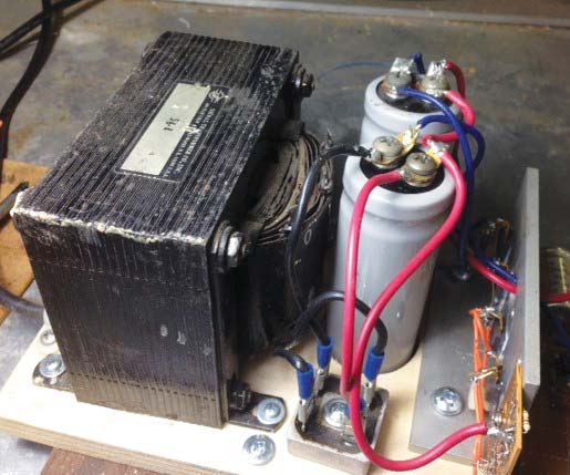
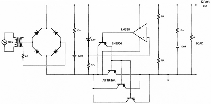
I assembled a pile of assorted parts: two used 10,000 µF 40V electrolytic capacitors; a used Signal 56/4 power transformer with a 14 volt secondary; a heatsink mounted power rectifier bridge, and, of course, my box of TIP30A transistors. The TIP30A is a medium power device in a TO220 package with a rated constant current of one amp, so my design required three devices in parallel mounted on a good heatsink to provide this.
The TIP30A has a minimum hFE of 40 which demanded an additional Darlington mode 2N3906 drive transistor from the LM358 op-amp. The bridge produced 19 VDC unloaded, so the volt drop across the control elements is about six volts. The power dissipated in the control elements is about 15 watts.
Loop Drive Amplifier
| Diode |
1N4148 |
D2 |
| Ceramic Capacitor |
100 nF |
C3, C4, C5 |
| Ceramic Capacitor |
100 pF |
C6 |
| Op-amp |
LMC6482 |
|
| Zener Diode |
5.1V |
D1 |
| Table Text |
TIP30A PNP |
T6, T7 |
| Signal Transistor PNP |
2N3906 |
T5 |
| 1/4W Carbon Film |
10K |
R4 |
| 1/4W Carbon Film |
100K |
R5, R6, R8 |
| 1/4W Carbon Film |
47K |
R7 |
| 1/4W Carbon Film |
3.3K |
R9 |
| 1/4W Carbon Film |
1K |
R10, R11 |
| 1/4W Carbon Film |
100 |
R12, R13 |
| Custom Wire Wound |
0.6 ohms |
R14, R15 |
Drive Amplifier Parts List.
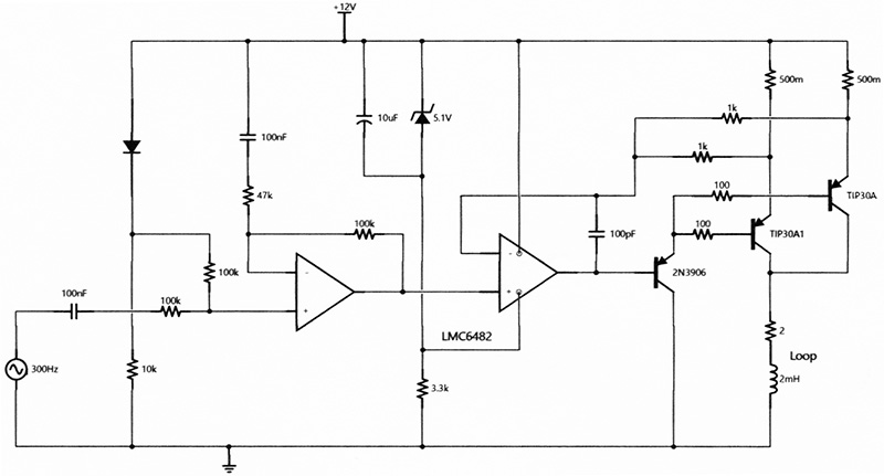
The resistance of 22 AWG wire is rated at 19Ω/1000 feet; my loop measured 1.3Ω in parallel and 3.6Ω in serial mode. The loop is represented in the schematic by the two-ohm resistor and the 2 mH inductance. The current through these components is the sum of a constant current and the audio signal current.
In this circuit, a constant DC voltage V1 (one diode drop referred to the 12 VDC rail) is added to the audio signal V2 at the non-inverting input of the first op-amp. This amp has unity DC gain and signal gain of about two, giving the drive voltage of (V1+V2) at the second op-amp. This voltage is impressed upon the 0.6 ohm resistors generating the loop current (V1+V2) / 0.6 x 2 [note the two output drive transistors]; the drive current is (V1+V2) amps. That’s about 2 ADC plus the audio component whose amplitude is limited to about 1A pk-pk. The 0.6Ω resistors were made using 24 AWG brass picture wire wound around a vitreous power resistor.
The headroom available to drive the loop with 2A from my 12 VDC supply is perhaps 10V, which limits the loop resistance to a maximum of about 5Ω corresponding to a wire length of 200 ft (60 ft dia) of single strand or 600 ft (180 ft dia) of triple strand 22 AWG wire.
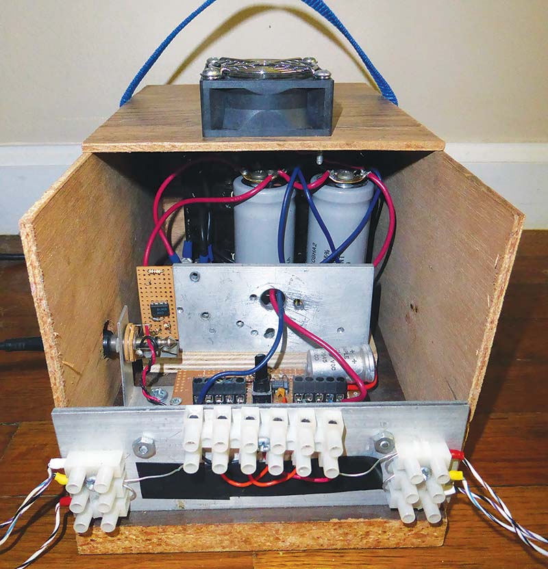
By using screw strip connectors and color-coded pins on the wires, it was easy to swap from serial to parallel operational mode.
On testing the loop drive using the hearing aid T-mode, an iPad voice recording came through loud and clear. This signal amplitude was measured to be about 1V pk-pk.
Success! There was no background noise and no apparent distortion. The signal was clear at ear level about six feet above the loop, and I could walk anywhere within the loop. The signal was good all over within the loop; outside the loop the signal decayed to an inadequate level after a distance of about six feet.
I mounted the finished power supply and driver in a simple plywood housing and added a small cooling fan to provide some ventilation. Finally, I added a nylon strap (located off-center) to make the unit balanced and easier to carry. After the fact, I looked up the International Standard for induction loops. It calls for a magnetic field strength of 400 mA/meter and a bandwidth requirement of 100-5,000 Hz. My system field H equals N.I/2/R and evaluates to 500 mA/m for the single loop, then 1,500 mA/m for the triple loop.
There’s a commercial loop system marketed by Williams Sound which advertises a seven amp system and advocates an insulated copper tape as the loop material, which seems to me to be a good solution to the problem of fixing a wire loop to the floor in an unobtrusive and reliable way. I see that they also have solved the problem of handheld receivers for folks who don’t yet have suitable hearing aids.
Receiver Design Parameters
The electronic part of my hearing aid is approximately a 1/4 inch cube, containing very sophisticated circuitry. It’s hard to believe that the magnetic field detector within the hearing aid is a discrete conventional ferrite cored coil with many turns of fine wire, but easier to believe that — in reality — is a Hall effect sensor fully integrated into the chip.
The most sensitive discrete linear Hall-effect device I could find has a sensitivity of 100 mV/mT. Maximum modulation amplitude is 0.6 μT, corresponding to a signal of 60 μV from the Hall-effect device.
In my application — assuming maximum modulation of the base flux density — the voltage developed by a small Ferrite-cored coil (using the following parameters) would be given by:
E = - N . dϕ/dt = - N.A. dB/dt Tesla,m2/Sec that is volts
Using a Ferrite bobbin 12.5 mm long and 1.5 mm diameter, effective permeability of the core is about 30 (reduced from material value >3,000 by a demagnetization factor of about 0.01).
If = 2,000 turns : A = π x 0.00152/4 = 1.7x10⁻⁶ : max ΔB = 0.6 μT : Δt = 10-3 (Period of 1 kHz)
Then, E @ 1 kHz = 2,000 x 1.7x10-6 x 0.6x10-6 x 30 / 10-3 = 61.2 x 10-6 = 600 μV
This estimate is 10 times the output given by the Hall-effect device, so the coil approach was decided upon.
Portable Receiver Design
| Signal Transistor NPN |
2N2222 |
T8 |
| Ceramic Capacitor |
100 nF |
C7, C8, C9 |
| Ceramic Capacitor |
2 nF |
C10 |
| Audio Amp |
LM386 |
|
| Electrolytic Capacitor |
10 µF |
C11 |
| Tantalum Capacitor |
1 µF |
C12 |
| 1/4W Carbon Film |
220K |
R16 |
| 1/4W Carbon Film |
68K |
R17 |
| 1/4W Carbon Film |
33K |
R18 |
| 1/4W Carbon Film |
1.5K |
R19 |
| Speaker 2” dia |
8 ohm |
|
| AA Battery & Holder |
1.5V |
Qty 4 |
| ABS Plastic Housing |
5”x2.5”x1.5” |
|
| Amidon Ferrite Bobbin |
B-72-111 |
|
| Single-pole Switch |
|
|
| LED and Series 10K |
|
|
Receiver Parts List.
Design parameters are:
- Amplifier Gain ~ 2,000 minimum (1V out for 600 μV in)
- Audio Bandwidth at least 300 Hz to 3 kHz
- Low quiescent power, preferably single AA cell
- Output to be clearly heard in handheld position
In keeping with my available parts theorem, I found a few Ferrite bobbin cores (Amidon #72-1111; at least 25 years old) and a spool of 40 AWG magnet wire. I wound as many turns of 40 AWG magnet wire as I felt would fit.
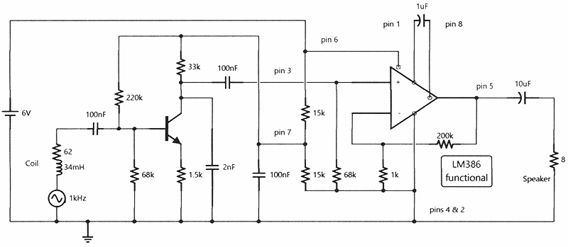
The coil resistance was 62Ω and the inductance measured 2 mH. Estimated N was between 1,600 and 2,200 turns.
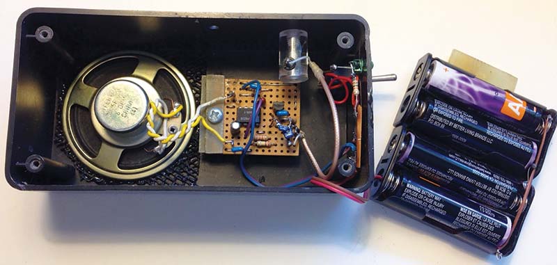
I designed the circuit using the LM386 audio amplifier chip which required a minimum 4V supply. My battery holders were twin AA, so my supply was six volts. I found it necessary to use the filtered pin 7 on the LM386 as the supply to the front end and to prevent distortion from noise on the supply line.
Gain from the LM386 was selected as 200, and the input stage 2N2222 was 22; more than sufficient at 4400. Two problems arose in mounting the circuit in a plastic box.
One was using an inductive pick-up near a loud speaker needs care in positioning to prevent feedback, and the second was proximity to the pick-up coil of current carrying wiring. The high gain system demanded the 2000 pF cap to prevent instability.
Wrap-Up
In conclusion, test of the system showed a comparable performance between the hearing aid’s built-in Telecoil feature and the handheld device. I was surprised that the handheld unit was so tolerant of its orientation in the loop field. The device was excellent for speech, but sounded a bit tinny for music.
It was a fun project full of challenges and surprises. It would probably be a more practical system if it ran on a lower loop power supply voltage like 5V, and it would be nice if the receiver ran on a single AA cell.
On reflection, it would be possible to make the loop using a surplus 100 foot spool of 50 conductor ribbon cable. Each conductor is seven strands of 40 AWG listed at 0.93 ohms/foot. So, wired in parallel, we would have a flat cable with about 1/3 ohm per 100 feet which would make a 5V drive system a reality. Using a ribbon with its low profile would make the installation unnoticeable. NV