Our “Digital Systems Design Using Microcontrollers” class at Cornell University culminated with a five-week independent design project. In that project, the instructor provides a $125 budget for us to create anything we want using a PIC32 microcontroller (anything that is safe and within practical limits of course!). While brainstorming project ideas, we realized that we all particularly missed visiting amusement parks during the COVID-19 pandemic. So, we decided to build something that would bring some of the excitement of those parks into the lab. In particular, we thought that using LEDs on an LED strip would be a creative and exciting way to visually simulate different rides. With inspiration and perseverance, we created a project that we were proud of.
Our project consists of a 2m DotStar LED strip with 120 individually addressable LEDs and seven inertial measurement units (IMUs) connected to a PIC32 microcontroller via SPI and I2C, respectively. It can emulate three different types of rides that are typically found in an amusement park: the roller coaster; the drop tower; and the bouncer. The LED strip represents an amusement park ride, and the LEDs that light up along the LED strip represent the riders.
We implemented 1D kinematic equations to approximate real world physics on the LED strip, and used multithreading (with Protothreads, invented by Adam Dunkels) to program the PIC32 processor. We also created a user interface in Python to make the system more interactive and allow the user to easily change various settings.
Background Physics
Our IMUs, which measure angular velocities and linear accelerations in three dimensions, are attached to the back side of the LED strip at regular intervals as shown in Figure 1.
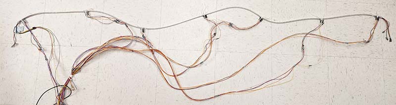
FIGURE 1. LED strip with IMUs and wires.
We first tried to calculate the absolute position and shape of the LED strip in three-dimensional space from the sensor readings, but we soon found this to be very error prone.
One way to do it would be by first calibrating the LED strip at a known initial position (e.g., flat on the table) and slowly moving to the desired shape. Meanwhile, we could integrate the gyroscope and accelerometer measurements to maintain an estimate for position.
However, we concluded that this approach was not preferable because these calculations involve many approximations, such as the radius of curvature when converting from angular velocity to linear velocity, not to mention that the IMU readings are inherently noisy.
Ultimately, we decided to update the rider’s position using only the y-acceleration measurement from the IMU closest to the rider (the LEDs that are on). This was the only reading we needed because it was the axis oriented parallel to the LED strip, and its magnitude and direction would tell us the slope of the strip at that location.
To calculate the next LED position to turn on, we used 1D kinematics equations as shown below given the initial velocity and initial position along with the measured y-acceleration value.
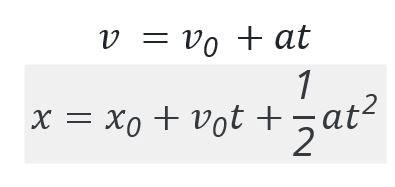
To calculate the current velocity of the cart, we used the velocity at the previous timestep along with the y-acceleration reading from the accelerometer closest to the head of the cart. To update the current position — which would tell us which LEDs to light up — we used the position and velocity from the previous timestep. This process is represented pictorially in Figure 2.
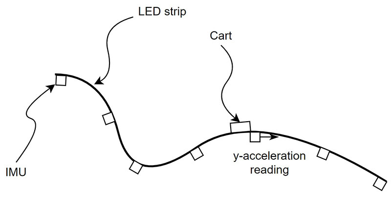
FIGURE 2. Representation of the LED strip with IMUs; the “cart” is composed of the specific LEDs that are lit up.
Doing this iteratively meant that we didn’t need to calculate the absolute shape and position of the LED strip, which would have been more complicated with no performance benefit.
Electrical Design
The main components in our project include the PIC32 microcontroller, an Adafruit DotStar LED strip, seven MPU6050 IMUs, and a USB to TTL serial cable for our Python user interface. A full hardware schematic is shown in Figures 3 and 4.
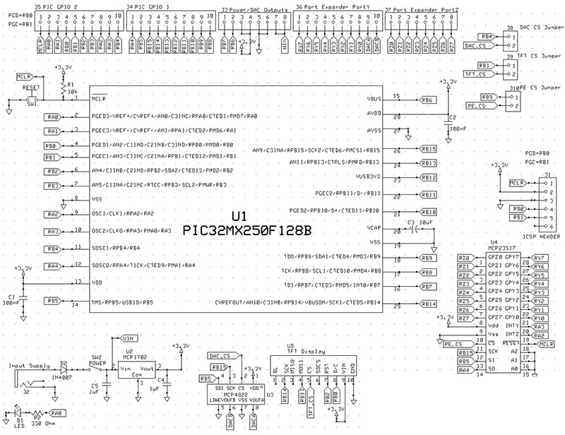
FIGURE 3. Electrical schematic of the PIC32 microcontroller development board we used.
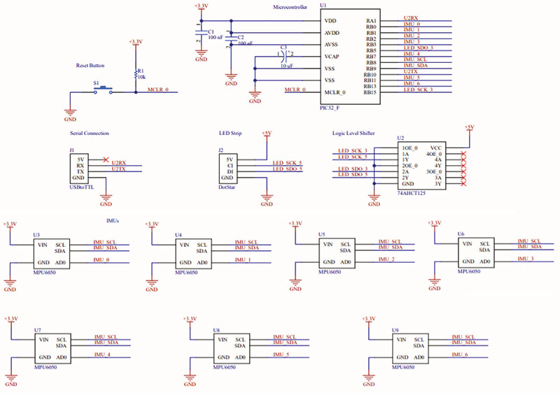
FIGURE 4. Electrical schematic of the components we connected to the development board.
The LED strip we used communicates with the PIC32 using 2-wire SPI. Because the LED strip is a 5V device while the PIC32 is a 3.3V device, we used the 74AHCT125 level shifter to translate the 3.3V clock and data line from the microcontroller to 5V for the LED strip.
We used MPU 6050 IMUs on individual breakout boards, each of which communicates with the PIC32 using I2C. Each IMU has two address options with only the last bit different. One pin on the breakout board is used to toggle the last bit of its address. We were able to connect more than two IMUs on the same I2C bus by dynamically changing each sensor’s address when we wanted to read to or write from it. We use the address with the last bit low to communicate with the sensor. This means that when we want to talk to a specific IMU, we clear that chip’s address pin and set all the other’s address pins. In effect, we use the address pin as a chip select.
Each sensor’s address pin needed to be individually mapped to a GPIO pin on the PIC32 to be able to be independently manipulated. This was a pin-intensive undertaking, and we had to carefully avoid pins that were already being used by other parts of the project such as those for the UART connection for the Python interface and the SPI connection to the LED strip.
To make our project interactive, we set up a USB to UART connection so that the user could manipulate variables in the user interface (a Python program) on the computer and the changes would be reflected in the running C program immediately, ensuring that the baud rate matches between the C program and the Python program.
Software Design
Within our C program, we have the main() function and three types of threads: a thread for reading the IMUs; a thread for calculating and updating which LEDs to light up; and threads for interacting with the Python user interface.
The IMU thread makes use of an IMU library inspired from the one created by a previous student group (cited in the Resources section). With this IMU library, we read the values from each of the seven sensors placed on the LED strip. By using global variables, we can use these values outside of the IMU thread in the LED thread, which calculates and updates the LED positions to turn on in the next time step. This way, we can dynamically change the position and shape of the LED strip, and the movement of the riders will change accordingly in real time.
The LED thread is where most of the calculation happens. In this thread, we first check the current position of the traveling light (the position of the LED that is turned on to denote where the riders are in the current time frame) on the LED strip and use the reading of the accelerometer that is closest on the LED strip as the acceleration value. Then, we check the current mode which indicates whether it’s in the roller coaster, the drop tower, or the bouncer mode.
For each of the modes, a slightly different kinematic equation is used to update the position of the traveling light in the next time frame. For the roller coaster mode, we used the basic kinematic equation explained in the Background Physics section. For the drop tower mode, we used the same equation but added a constant upward movement at the beginning and waited at the top of the ride for a random amount of time before implementing the kinematic equation to mimic the behavior of the ride more closely.
For the bouncer mode, we use the two different equations: the same equation as the roller coaster mode when it’s moving downward; and the equation with the negative speed once it reaches the end of the strip and travels back up the LED strip.
No explicit damping was added to mimic air resistance; we felt that the force of gravity alone already made this mode look realistic. A simplified diagram representing our code is shown in Figure 5, where the kinematic equations use the closest accelerometer value if the ride has not been stopped.
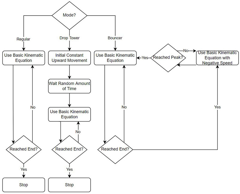
FIGURE 5. Block diagram of the code.
Because we wanted each mode to behave slightly differently even with the same equation, we controlled how often the LED thread would be scheduled, i.e., how often the LED updates would occur. This changes the apparent speed of the rider along the LED strip.
For example, the lights for the drop tower reach the bottom of the strip at the same time as a real object that is dropped from the same height. On the other hand, we slowed down the speed of the roller coaster so that we can visually examine that its behavior is clearly affected by the physics and the shape of the roller coaster. We used the DotStar example code from our course website to send the updated values for each pixel on the LED strip (cited in the Resources section).
We made our project more interactive by implementing a Python user interface with PySimpleGUI. Users can choose the ride they want to go on, the initial velocity of the ride, numbers to simulate friction, and even what color and how long the ride train should be. It also includes a reset button to restart the ride with the parameters that are set.
An image of the interface is shown in Figure 6.
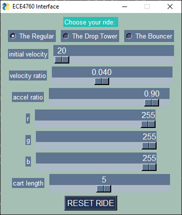
FIGURE 6. Python user interface.
We use radio buttons to choose the ride, a normal button for the reset, and sliders for the remaining settings, so we included threads to support those functions in our code. These threads yield until an event happens on the interface. We used the sample code provided in the article downloads (and also on the course website) to help us with that (see the Resources section).
The main() function handles all the initialization, including initializing and scheduling the threads; opening an I2C channel for the IMUs; setting up each IMU (by assigning each of them a separate GPIO address pin, taking them out of sleep mode, and setting the accelerometer range to ±2g); opening an SPI channel for the LED strip; and turning off all the LEDs on the strip.
Problems, Resolutions, and Notes
The amount of wires we used to connect each of the sensors to the PIC and the LED strip oftentimes became overwhelming to keep organized. Each sensor required five wires: 3.3V power, ground, SCL, SDA, and an address line. We color coded the wires so that we could easily tell which wire corresponds to which pin. We also made sure to tape the stripped wire endings so they wouldn’t short.
As a side note, we tried to use less wires by creating the wire harness shown in Figure 7, but it ended up being even more problematic when we were trying to debug our project because of the poor connections and inability to easily detect connection quality.
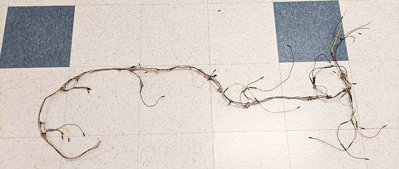
FIGURE 7. Attempted wire harness.
Before we set up all the sensors in our system, we tested them individually. From our testing, we realized that the readings were quite noisy even when the sensor was sitting still on a surface. Using raw values led to abrupt jumps in the LED positions, which corresponded to unnatural-looking behaviors of the riders through the LED strip. To reduce the jitter, we low-pass filtered the readings in our code by shifting the four least significant bits of the readings out and shifting zeros in. The software solution was a simple single line of code, but it allowed us to receive much more consistent readings from the IMUs, and hence update the LED cart’s position in a much more smooth manner.
One frustrating bug we encountered was not properly taking the sensors out of sleep mode. This happened as an artifact from when we had done IMU testing one by one. When we were adding sensors by mapping a new GPIO pin to each, we accidentally neglected to also initialize each of the sensors we were adding. The way the code was initially formatted caused us to only be initializing the last sensor we added, which resulted in a confusing false positive where they all seemed to be working when we added each sensor one by one (since they would all retain their state of having been taken out f sleep mode) but all of a sudden wouldn’t work when we ran the same exact code again the next day and/or power cycled the microcontroller.
This problem was only exacerbated by the fact that we didn’t know whether it was a hardware issue with wiring or a software issue.
Another interesting thing to note is that the I2C protocol is intended to only be used for short intra-board communication but could be pushed to longer distances with a lower clock frequency. We were able to reliably communicate up to our farthest sensor which was two meters away by setting our I2C clock frequency to be 100 kHz.
Results and Conclusions
Our project successfully demonstrated three different types of amusement park rides with an LED strip. It could dynamically respond to our movements and orientation of the LED strip, which we had envisioned from the beginning. Our design focused on making the entire “roller coaster” and other rides look as natural as possible. To achieve this, we made sure to read from the sensors and update the LED cart position at a rate that would look natural to our eyes. We removed any additional threads that weren’t needed during our final design. For example, the print thread we used for debugging — which was printing the sensor readings of each IMU — took a long time to execute. We noticed pauses in the roller coaster due to it waiting for everything to print out before continuing onto the other threads. After removing this, we were able to see much smoother execution.
To demonstrate the “realistic” movements of our roller coaster, we put the strip in several different configurations as seen in the demo video (see Resources). One such configuration was in the shape of a parabola, to show that the cart would settle down close to the minimum of the parabola. We also tried a loop so we could see that the LED cart would slow down at the very top of the loop, and then speed up on the way down.
Another important result we wanted to highlight was our free fall “drop tower” ride. This was a simple drop tower composed of the LEDs climbing to the top of the strip, waiting for a random amount of time, and then falling down in almost the same time that it takes a physical object to fall. We showed this with a pen in the demo.
To make this project much more aesthetically pleasing, we could have included additional colors while the LED cart is moving throughout the LED strip. For example, if the cart is moving faster, it can be changing colors more rapidly, and while it’s moving slower, it can gradually change colors to offer a visually enjoyable experience for the user.
One thing we would have liked to implement (which would’ve require a larger budget) is adding more sensors to our project. More sensors would give our LED cart more accuracy whenever it updates its position because the closest IMU wouldn’t be as far away, and it wouldn’t awkwardly stop in the middle of two sensors if one is at a horizontal position.
The use of sensors to get data was a great way to get more experience in using I2C devices. Alternatively, a different way to achieve a similar effect as suggested by our professors would be to use computer vision on the LED strip, and based on how it was oriented, change the velocities of the LED cart. This would require a much more software-focused approach, but could be an interesting implementation for the future.
Though there are certainly things we could have done better or differently, in the end, we were very happy with how our project turned out. NV
Parts List
| Development Board |
| Part |
Value |
Qty |
| C1,C2 |
100 nF |
2 |
| C3 |
10 µF |
1 |
| C4,C5 |
1 µF |
2 |
| D1 |
LED |
1 |
| D2 |
1N4007 (SMT diode) |
1 |
| J1 |
ICSP Header Plug |
1 |
| J2 |
Input Supply |
1 |
| J3 |
Power/DAC Outputs |
1 |
| J4,J5 |
PIC GPIO1,2 |
2 |
| J6,J7 |
Port Expander PortY, PortZ |
2 |
| J8,J9,J10 |
DAC, TFT, PE CS Jumper |
3 |
| R1 |
10K Resistor |
1 |
| R2 |
330 ohm Resistor |
1 |
| SW1,SW2 |
Reset, Power Switch |
2 |
| U1 |
PIC32MX250F128B |
1 |
| U2 |
MCP1702 |
1 |
| U3 |
MCP4822 |
1 |
| U4 |
MCP23S17 |
1 |
| U5 |
TFT Display |
1 |
| Other |
5V AC Adapter |
1 |
| Other Components |
| Part |
Value |
Qty |
| J1 |
USB to TTL Cable |
1 |
| J2 |
LED Strip |
1 |
| U2 |
Logic Level Shifter |
1 |
| U3,U4,U5,U6,U7,U8,U9 |
MPU 6050 Breakout Boards |
7 |
| Other |
5V AC Adapter |
1 |
| Other |
Female AC Adapter Socket |
1 |
Downloads
What’s In The Zip?
All Necessary Code Files