Most frequency counters can tolerate only low levels of RF at their input, but here’s a way to safely measure the frequency of an RF signal of up to 200 watts with your existing frequency counter.
This buffer allows you to connect your counter to any RF source from 20 mW to 200 watts, from 200 kHz to 60 MHz. The circuit has a protection limiter that keeps the RF signal strength in a safe range for the TTL input of the counter, as well as providing gain for weaker signals (Figure 1).
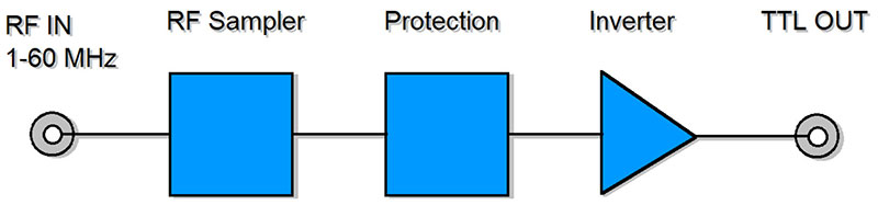
FIGURE 1. Block diagram of frequency counter buffer.
You can think of the buffer as a dam safely keeping high water out of Frequency Counter-ville. If the water/signal is too high upstream, you can limit how much of it gets through. Or, if its strength is too low, you can add some. It helps with low signals by using the gain of an inverter and holds back high signals with voltage protection, all on the same printed circuit board (PCB).
Purpose
There are many forms of RF buffer circuits that do some of the same things. This one isn’t the fastest, strongest, widest, or prettiest RF buffer ever made, but it’s right in the sweet spot for HF transceivers. It performs well, is easy to reproduce, is low cost, and has a minimal parts count.
Most amateur HF transceivers are in the 5 to 200 watt range. This buffer (Figure 2) will allow you to connect your standard desktop frequency counter directly to the RF line, even with higher signal levels that most frequency counters can handle. For Citizens Band, most transceivers are in the 4 to 12 watt range and will work fine with the buffer.
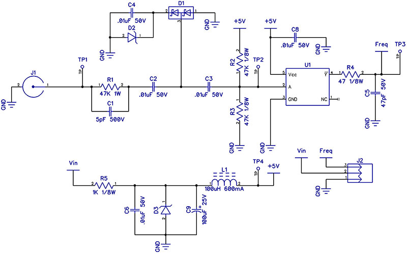
FIGURE 2. Schematic of frequency counter buffer.
The low end of the buffer’s power range covers the smallest of transmitters. For instance, the FCC (Federal Communications Commission) allows experimenters to transmit up to 100 mW in the AM broadcast band, and the new amateur bands at 135 and 472 kHz. The buffer is also an excellent front-end for an Arduino, PIC, or your favorite microcontroller for your next HF project.
How It Works
The RF input is shown in Figure 3 as measured at Test Point 1. It shows a five watt signal on 14 MHz into a 50 ohm dummy load. R1 and C1 comprise the sampling section.
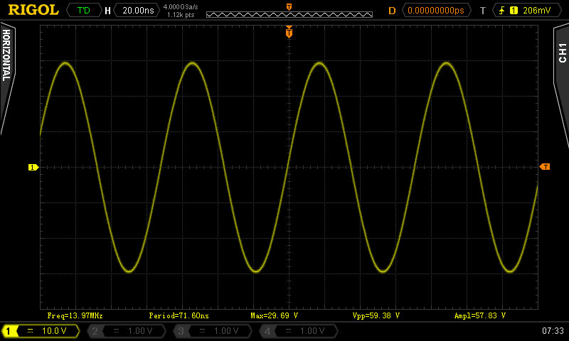
FIGURE 3. RF input, five watts on 14 MHz.
R1 samples some of the RF from the signal as shown in Figure 4.
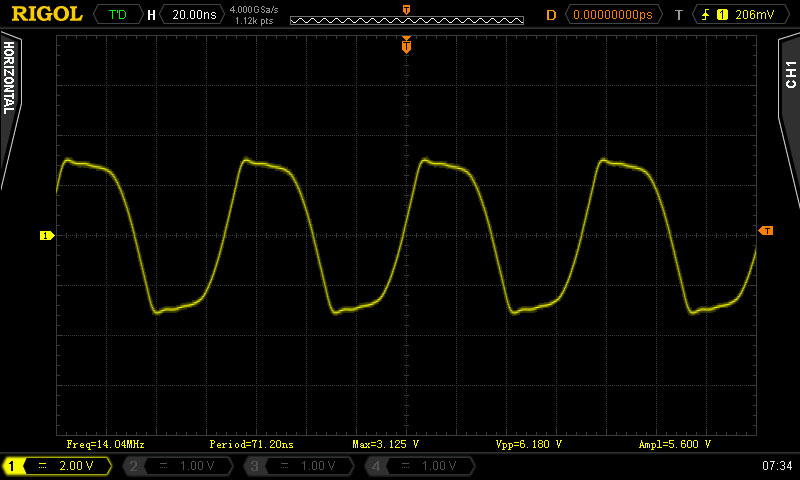
FIGURE 4. Sampled RF waveform.
R1 has to dissipate a little of the power, so at one watt, it’s somewhat bigger that you may expect. C1 shapes the frequency response and provides better sensitivity above 20 MHz as shown in Figure 5.
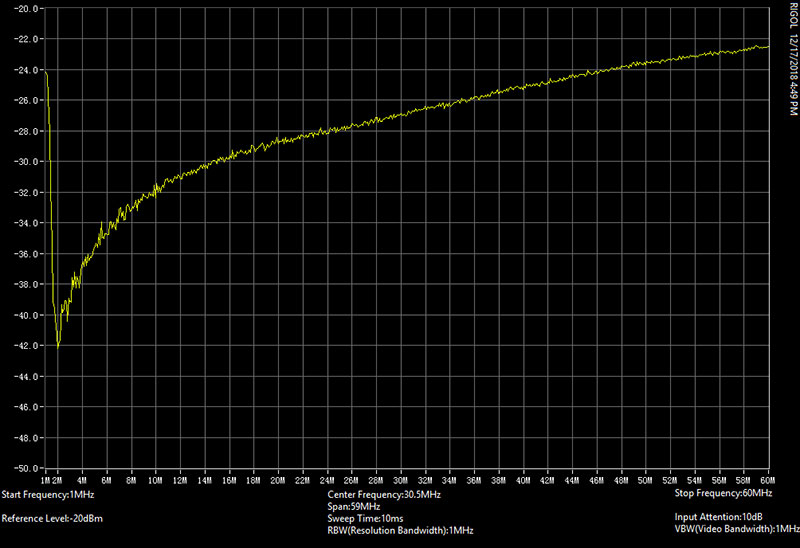
FIGURE 5. Frequency response of RF sampler.
C2 couples the sampling section to the protection section, and diode D3 provides protection by limiting negative-going signals stronger than about -0.5 volts. Diode D2 and D3 provide protection from signals above five volts. Once the voltage at D2 goes above about five volts, zener diode D3 will conduct to ground.
These components limit the signal to between 5.0 volts and -0.5 volts as shown in Figure 6. C3 couples the protected signal to the input of the inverter chip U1 and Test Point 2; R2 and R3 bias U1 for the best gain response.
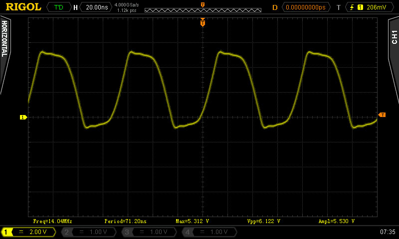
FIGURE 6. Level protection for input of inverter.
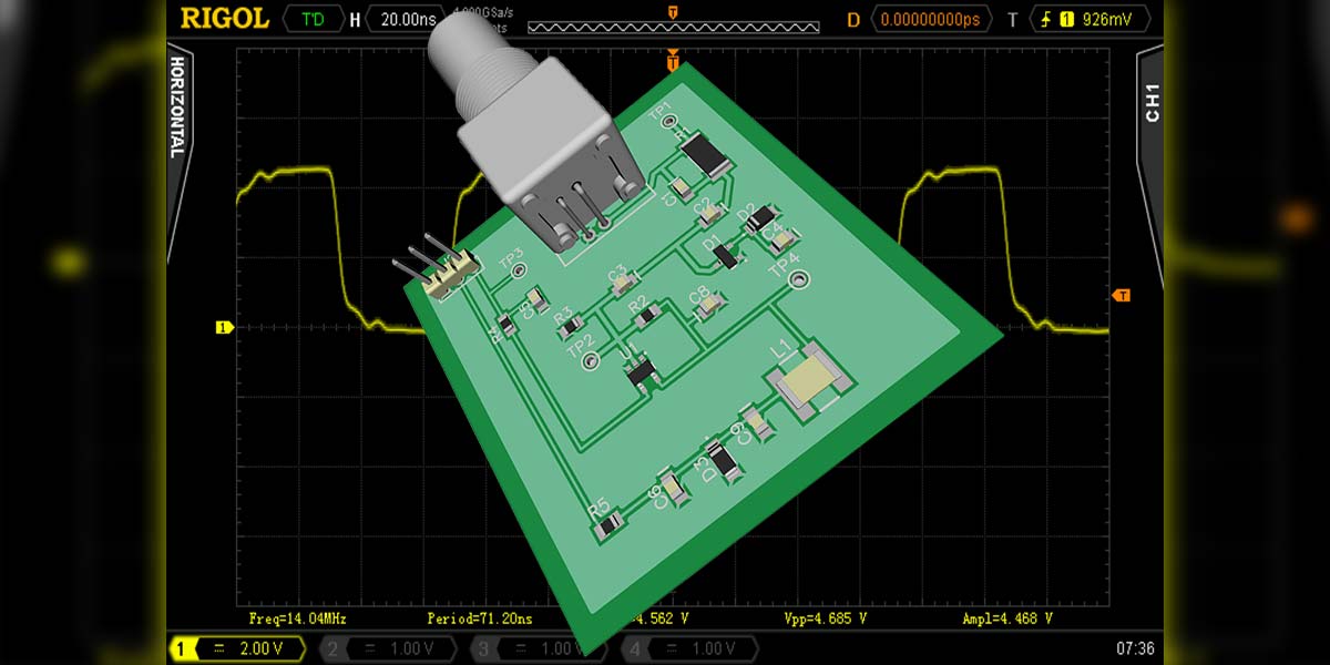
The output of U1 at TP3 is a TTL compatible signal (Figure 7) ready to go to your frequency counter. R11 and C22 reduce harmonics to the timer pin.
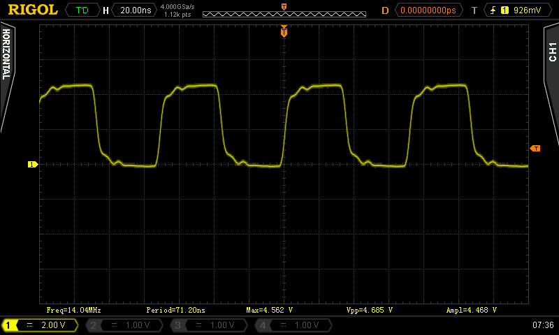
FIGURE 7. TTL output of buffer.
The total response of the system is shown in Figure 8.
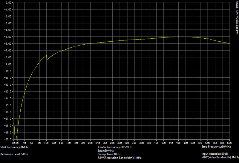
FIGURE 8. Total bandwidth of 60 MHz.
For the Engineering Geeks
Here, we’ll take a little deeper look at each section. You can skip this part if you don’t need the nitty gritty details, but remember it’s here later if you want more information.
R1 samples enough RF to drive the inverter. The one watt rating could be increased here to build a higher-powered buffer, but the tradeoff would be decreased sensitivity in the low power range.
C1 provides a roll-off of frequencies below 14 MHz and passes frequencies above 25 MHz. This helps to make sensitivity across the frequency range more uniform.
AC coupling capacitor C2 blocks any DC on the RF line. This is important as many newer radios use DC power on the coax for antenna control or remote antenna switching.
The limiting section D1 and D2 are fast switching diodes. They can switch up to about 200 MHz — plenty for the 60 MHz bandwidth we need.
D3 and C4 provide an RF shunt to ground when D1 conducts. C4 will shunt any RF to ground during the few milliseconds it takes to charge to the zener voltage. Once the breakdown voltage is reached, the diode will operate stably. Special thanks to Gregg Neumann VK3GMN for this part of the circuit.
What is a Frequency Counter?
An RF frequency counter is a test equipment item that can measure the time interval of a signal and display the answer in Hz, kHz, MHz, or GHz. The range of an RF frequency counter is usually measured in MHz but can also be down to kHz and up to the GHz range. For most amateur HF transmitters, the output frequency is between 1 MHz and 60 MHz, and RF power levels between 5 and 100 watts.
Many DIY frequency counter kits are available that have a TTL level input such as the EZM 50 MHz frequency counter. When measuring RF that uses a 50 ohm system, just a few watts of RF power can overload the front-end of a TTL input. This article shows the RF power sample of a five watt transmitter using a 50 ohm load is about 40 volts peak-to-peak.
The 40 volts would easily damage the TTL input of a PIC, Arduino, or other counter with a TTL input with a max of five volts and a min of zero volts. In this case, an RF buffer would certainly be needed to protect the counter.
The key thing to note about the D2/C4 circuit is that it will provide protection without being connected to the +5 volt DC power supply bus. This approach has two advantages.
First, this circuit still acts as a protection device for your counter even if the DC power is off. Second, any signal over five volts is sent to ground and helps keep noise off the +5 volt bus. This also provides protection to keep larger voltage spikes from entering the power supply +5 bus. If you’re monitoring an RF line that goes to an antenna, it gives your counter some protection from static.
The bias circuit R2/ R3 centers the AC signal at around 2.5 volts and creates a sensitive zero-crossing detector at the input stage of the inverter. The center voltage is the sweet spot for low-level RF signals to drive the inverter high or low and gives the best bandwidth response. With the input of U1 biased, the bandwidth gain is usable up to 100 MHz, and provides a good TTL level output for counting.
The DC supply section is straightforward. Again, we use a zener diode to provide the +5.0 volt regulation at TP4 to keep the inverter stable. C4, C5, and C6 help keep the regulator stable, and provide additional filtering.
PARTS LIST
| NAME |
QTY |
VALUE |
VALUE 2 |
STYLE |
BRAND |
MOUSER PART# |
| U1 |
1 |
74LVC1G04 |
|
SOT-23 |
TI |
595-LVC1G04QDBVRQ1 |
| D1,D2 |
1 |
BAT46 |
|
DO-35 |
ST Micro |
511-BAT46 |
| D3,D4 |
1 |
1N4733 |
|
|
Vishay |
78-1N4733A |
| R1 |
1 |
47K |
1W |
|
Yageo |
603-FMP100JR-52-47K |
| R2,R3 |
2 |
47K |
.125W |
|
Yageo |
603-CFR-12JR-5247K |
| R4 |
1 |
47 |
.125W |
|
Yageo |
603-CFR-12JR-52470R |
| C1 |
1 |
5 pF |
500V |
|
TDK |
810-CC45SL3JD050DYNA |
| C2,C3,C4,C6 |
4 |
0.01 µF |
50V |
|
Kemet |
80-C316C103M5U |
| C5 |
1 |
47 pF |
50V |
|
Kemet |
80-C315C470K5G |
| C7 |
1 |
100 µF |
50V |
|
Nichicon |
647-UVR1H101MPD |
| L1 |
1 |
10 µH |
2.2A |
|
TDK |
871-B78108E1103K009 |
| L2 |
1 |
100 µH |
600 mA |
|
TDK |
871-B78108E1104J009 |
Ready to Count
We’re done! It’s time to go hook it up and measure some frequencies. You’ll need a 5-15 volt DC power supply and a BNC cable or adapter for the RF connection.
You can use a BNC Tee connector to attach to your coax line, or just clip a wire onto the post of the RF connector you want to measure. Transmit some RF into a dummy load or while making a contact on the air. You’ll be able to read the frequency over a wide range of RF power levels while safely protecting your frequency counter.
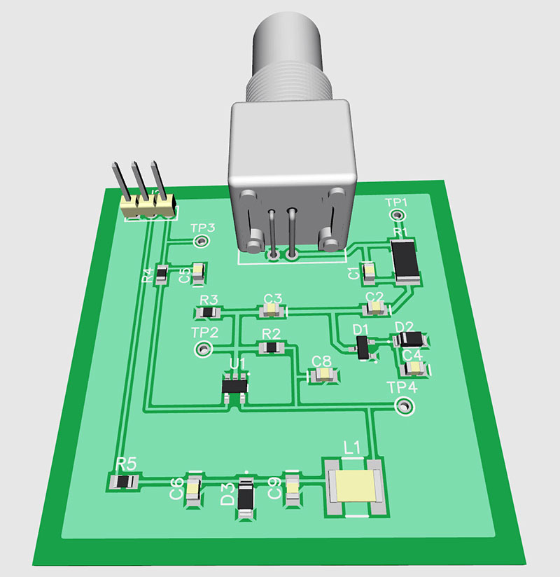
FIGURE 9. 3D model of printed circuit board.
A Fun Club Project
If your radio or electronics club has not done an assembly project in a while, talk to them about doing this one. It takes only about 15 minutes to assemble once the iron is hot, and another 15 minutes to test a bunch of them. Have a couple of your local Elmers bring in a frequency counter and a signal generator. There are no adjustments; just plug and play!
This RF buffer is a handy tool you’ll remember every time you use a frequency counter. You can easily make one for every counter you enlist to measure RF.
You know you’ll need it at the most important time while testing your six-meter transceiver, or that new 2,200 meter transmitter. Happy counting! NV
Corrections
On page 39 in the print edition, the sentence "The key thing to note about the D3/C4 circuit is that it will provide protection without being connected to the +5 volt DC power supply bus." has a typo. It should instead read D2/C4.
The correction has been made in the text above.
Downloads
What’s in the zip?
Bill of Materials
Assembly File
Gerber File
PCB File
Schematic