It was Christmas afternoon. The gifts had all been opened, and a substantial brunch had been consumed. The members of the household were all off doing their various things. The resident techie was wandering around the house with his new Dremel® tool, looking for something to grind, buff, drill, polish, or otherwise fold, spindle, or mutilate, when a voice called to him from somewhere in the house.
“Hon, have you checked the tree, lately?”
This was wife code talk for, “Add water to the Christmas tree, now please.”
This is one of those unspoken chores that the male of the species inherits unknowingly, simply because of his gender; it’s kind of like having to take the garbage out, only seasonal.
This process usually involves lying atop a pile of broken toys, while trying to pour a pitcher of water into a hidden tree holder, without spilling most of it on the floor, or onto that nightgown that you haven’t yet given to Aunt Agatha. There is a good probability that some of the water will never make it into the tree stand.
The resident techie found the whole process unpleasant, and decided the situation required some thought before launching into it. He built a braunsweiger sandwich, popped a can of inspiration, and went off into the living room to study the problem. He plopped into a chair, assumed the frowned-upon position (feet on the coffee table), and evaluated the problem. The snack was indeed inspirational. He eventually evoked an “Aha!” (and a burp), and trundled off to the workshop, detouring through the kitchen to pick up another cold one. The solution would be electronic, of course.
Description
The device that evolved is rather simple; it consists of a three-conductor probe (dipstick), a remotely mounted blinking LED which gives a visual indication of the low-water level, and a small box containing a two-IC control circuit, a buzzer, and a battery. See Figure 1.
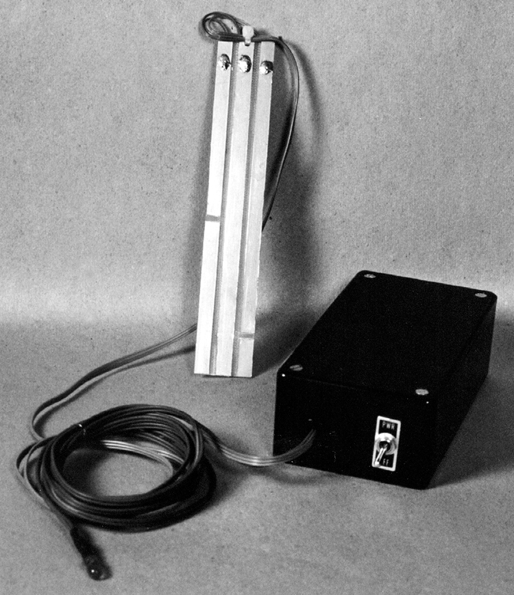
FIGURE 1 — CHRISTMAS TREE DIPSTICK COMPONENTS
consisting of PC board dipstick (rear), LED and cabling (left), and the control box.
The dipstick activates the circuit. When the full or low-level conductors are shorted by water to the common conductor, the circuit reacts. When the water level is below the low conductor, the LED flashes, until the water is filled enough to short the low conductor. As the water is filled more and contacts the full conductor, a buzzer sounds for about one second, which announces that the tree stand is full. The buzzer then shuts off until the water level drops below the full conductor, and is then refilled. When the water level is between the low and full conductors, which is where it will be most of the time, the LED and buzzer are off. This conserves battery power. When the LED is on, it blinks, which also prolongs battery life.
The LED is on the end of a long cable, which allows it to be mounted onto the end of a tree branch, where it can be seen. It can be secured to the branch with a dark colored twist tie. When the LED is off, it will be semi-invisible. If someone in the family is “artsy-craftsy,” the LED can be made part of an ornament; Rudolph’s nose, perhaps. If your tree has multicolored blinking lights, the LED probably won’t be noticed in amongst them. It would then be best to mount the LED away from the tree.
The final piece of equipment required to complete the system isn’t electronic, but nevertheless essential. A two-foot long transmission funnel (available at an auto parts store) can be used to fill the tree stand with a minimum of trouble. One only has to listen for the buzzer to tell when the tree base is full. A black or dark green funnel can be nestled between the branches near the backside of the tree, and left there. It will be invisible. A conventional funnel and a piece of plastic tubing will work, as well.
How it Works
The circuitry for the Christmas Tree Dipstick is shown in Figure 2.
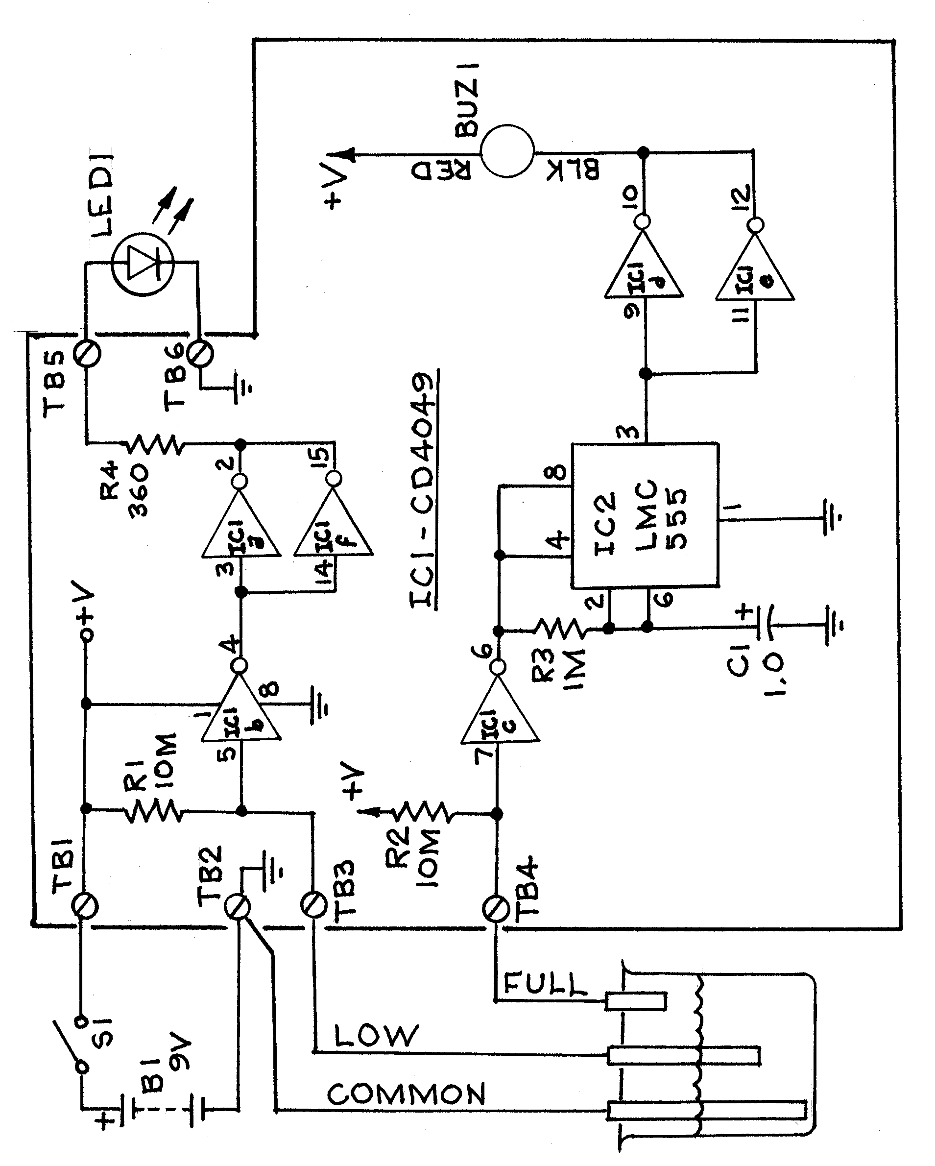
FIGURE 2 — CHRISTMAS TREE DIPSTICK SCHEMATIC DIAGRAM.
Consists of high- and low-water level probes, circuitry to turn on the low-level LED, and circuitry to activate a one-second buzzer for when the water level reaches full.
The “low” probe is connected to the input of the inverter-buffer gate IC1b (pin 5) through terminal TB3. The “full” probe is connected to the input of the inverter-buffer gate IC1c (pin 7) through TB4. These inputs are held high by pull-up resistors R1 and R2. When the “low” or “full” conductors are shorted to common by the water, these inputs are pulled low.
When the water level is touching the “low” electrode, the LED 1 indicator will be off. When the level falls below the electrode, it will no longer be shorted to common, and the input to gate IC1b (pin 5) will be pulled high by R1. The output of IC1b is then low. This output is inverted by gates IC1a and f, which output a high through resistor R4 and terminal TB5, to turn on LED 1. Gates IC1a and f are paralleled to furnish more output current. Resistor R4 limits the current to LED 1. The LED has a built-in flasher, so it blinks whenever it is energized.
When the tree stand is filled, and reaches the “full” electrode, the input to TB4 is pulled low. This makes the output of gate IC1c high, which also makes pins 4 and 8 of IC2 high. It is applying power to IC2, which is a CMOS 555 timer. Capacitor C1, resistor R3, and IC2 are configured as a power-up reset circuit. When power is applied, it will generate a single pulse output. It will not output again until the power is shut off, and then turned on. Resistor R3 and capacitor C1 determine the pulse length. Time = 1.1 x C1 x R3, and is about one second. Increasing the value of R3 or C1 will increase the buzzer on-time.
The circuitry operates from a nine-volt battery, which is switched by S1. The voltage supplies the circuit board through terminals TB1 (+) and TB2 (COM).
To recap the operation, when the water level is below the “low” level electrode, LED 1 will flash; when the water is filled, and reaches the “full” electrode, the buzzer sounds for one second. When the water level is between the “low” and “full” electrodes, nothing is activated. IC2 is not powered, so the standby power is extremely low. This increases the battery life considerably.
Construction
See Figure 3.
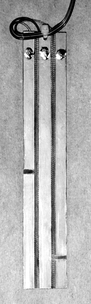
FIGURE 3 — CHRISTMAS TREE DIPSTICK ELECTRODES.
This is fabricated from single-sided PC board material. The foil is cut or etched away to make the individual electrodes. It is 1" x 6". The common electrode is in the center, the high-level electrode is on the left, and the low is on the right. The two horizontal foil cuts determine the high and low levels. A hole in the top of the board with a cable tie furnishes cable strain relief.
This is fabricated from single-sided PC board material. It can, of course, be etched, but it isn’t necessary. The conductor sections can be made by scoring lines with a metal straightedge and a utility knife. The foil between the sections can then be trimmed out with the knife. Separations between conductors can also be done by making shallow cuts with a table saw. The water depth of the tree stand determines the location of the full level foil cut.
The low level turn-on point should be a little above the bottom of the tree, so the tree stand is not quite empty when the low indicator turns on. The prototype unit low level is about 3/4”. The full level turn-on should be a little lower than spillover. About 1/2” works.
It is not necessary to use PC board material for the probe. Any conductors attached to a non-conductive carrier will work. Solid bare wire can be attached to a strip of Plexiglas, for instance. A hole was drilled near the top of the dipstick, and the lead-in cable secured with a cable tie, for strain relief.
The lead-in wire can be any small gauge three-conductor cable. The prototype uses a three-conductor strip peeled away from the edge of a ribbon cable.
LED Assembly
The LED was soldered to a small gauge two-conductor cable. The prototype used a piece of 26-gauge intercom cable. The length will be determined by its final location. It should be at least six feet long, so it can be placed at eye level. The LED leads are insulated with shrink tubing.
The cable color should be dark, so it won’t be noticed. Be sure to mark the LED polarity at the end of the cable that connects to the control module.
Enclosure
This is not sacred. Almost any enclosure that will hold the parts will do.
The hole sizes and locations are given in Figure 4 for the prototype box. If the battery holder is attached with double-sided foam tape, that hole can be eliminated.
Hole sizes for the switch S1 and the grommet are determined by the components selected.
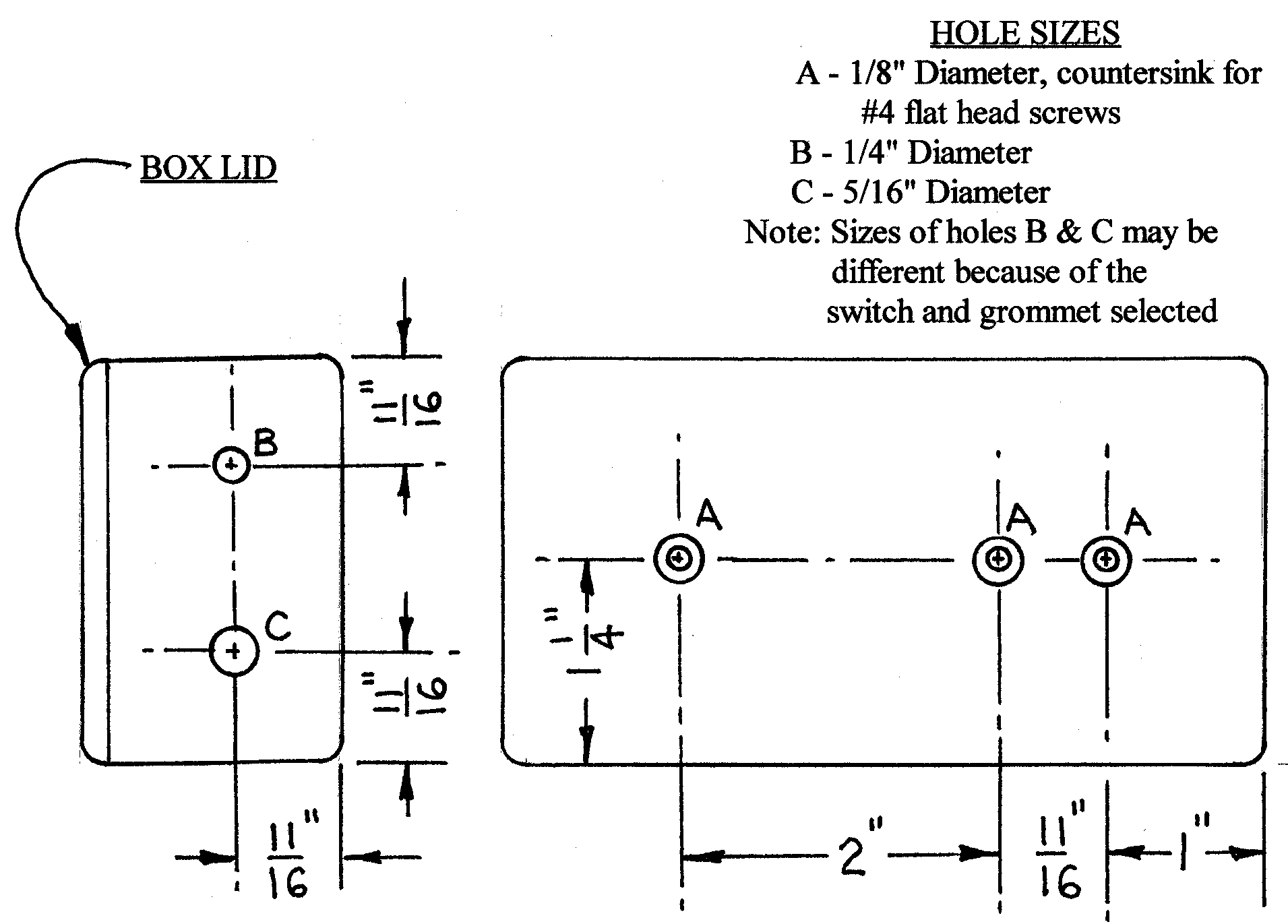
FIGURE 4 — ENCLOSURE DRILLING.
These hole locations and sizes are for the enclosure specified on the Parts List.
Control Circuit Module
See Figure 5.
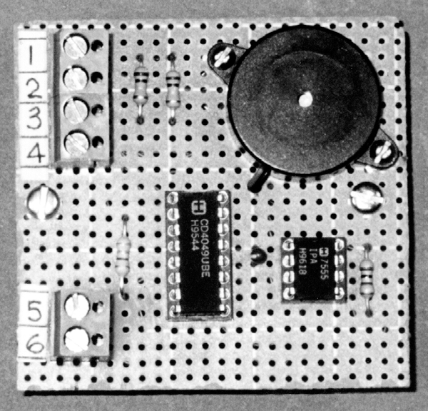
FIGURE 5 — CONTROL CIRCUIT MODULE.
This is assembled on the project board, and holds all the electronic components, including IC1, IC2, and the circular buzzer. The integrated circuits are installed in wire-wrap sockets. Component location is not critical.
Nothing is critical on this assembly. The circuit is simple enough to make with point-to-point wiring. Wire wrap was used for the prototype.
The components were mounted on project board rather than perf board. Project board has a solder pad around each hole, so the components can be soldered in place before wiring; it makes assembly easier. The project board was cut to fit the box. That size is 2-1/2” x 2-3/8”.
Wire wrap is designed to be used on square pins like those on the wire wrap IC sockets. When wire wrapping onto round leads — such as resistors — tack the wrap with a drop of solder for reliability. The circuit board is mounted on two 5/8” standoffs, to clear the IC socket pins.
The terminal blocks are not absolutely necessary; they do, however, make assembly and troubleshooting a bit easier. All wire lead-ins can, of course, be soldered directly to the board instead.
When routing the cables from the LED and dipstick through the grommet to attach to the control circuit module, add a cable tie to the cables just inside the grommet for strain relief, or wrap the cables around the circuit board standoff once or twice. If you’re a Boy Scout wannabe, a clove hitch works great. See Figure 6 for component locations in the box.

FIGURE 6 — CONTROL BOX ASSEMBLY.
Switch S1 and cables to the electrodes and the LED are shown on the left. The Control Circuit Module is located in the center, and the nine-volt battery is on the right.
Final Test
Install the battery. Put the dipstick in an empty glass, and turn switch S1 on. The LED should blink, indicating low-water level. Slowly fill the glass. When the level reaches the “low” level conductor, the LED should turn off. Continue to fill.
When the water level reaches the “full” conductor, the buzzer should sound for about one second, and shut off. Lift the dipstick so the “full” conductor is out of the water, and then lower again. The buzzer should sound again. Remove the probe from the water. The LED should blink again, until it is reinserted into the water. If the control doesn’t react immediately, wait a bit until the water drains off, and the conductors are no longer shorted. Shut the unit off, and install it.
Installation
Before mounting the tree into the tree stand, put two heavy rubber bands around the base of the tree. These hold the dipstick upright. Simply slide the dipstick in behind the rubber bands, after the tree is mounted. A long cable tie, or once around with electrical tape also works.
Be sure that any rubber bands or wrap-arounds are above the maximum water level. Water could possibly get in behind them, short the conductors, and give a false indication. Be sure the bottom of the dipstick is all the way to the bottom of the water reservoir on the tree stand. Mount the LED where it can be seen.
After the holidays, remove the battery to avoid any corrosion that might occur in storage. Christmas tree water can get pretty gunky, so wash the dipstick with soap and water, or alcohol before putting it away.
A fresh battery will easily last through a holiday season
If you are not a live Christmas tree family, don’t dismay. You still might find an application for this circuit. It was originally added to an old belt-type humidifier (el cheapo) that doesn’t have a low water indicator. The old hunk of junk is still plugging along, and so is its dipstick.
Anyway, Happy Holidays ... with or without the dipstick. NV
PARTS LIST FOR THE INCREDIBLE CHRISTMAS TREE DIPSTICK
| S1 |
DPDT (or DPST) Miniature Toggle Switch (RadioShack No. 275-612 or equivalent). |
| B1 |
Alkaline Battery, nine volt. |
| LED1 |
Blinking Light-Emitting Diode (RadioShack 276-036 or equivalent). |
| R1, R2 |
Resistor, 100K ohm, 1/4 watt, 5%. |
| R3 |
Resistor, 1M ohm, 1/4 watt, 5%. |
| R4 |
Resistor, 360 ohm, 1/4 watt, 5%. |
| C1 |
Capacitor, 1.0 mF, 16 WVDC (minimum) Electrolytic. |
| IC1 |
CD4049 CMOS Inverting Hex Buffer Integrated Circuit. |
| IC2 |
LMC555 CMOS Timer Integrated Circuit. |
| BUZ1 |
Buzzer, Piezo, 3-20 VDC (RadioShack No. 273-059). |
| TB1-TB6 |
Terminal Block - Optional. |
| MISC PARTS |
Project Box (Hammond 1591-CS or equivalent). Project Board (RadioShack No. 276-158), cut to size to fit Project Box. Battery Holder (RadioShack No. 270-326, or equivalent). Battery Snap Connector (RadioShack 270-325, or equivalent). Solder, Wire, Cables, Grommet, Hardware, 8- and 16-pin Wire Wrap IC Sockets, etc. |