Call me Noah. For I am here to save you from the flood. Or, at least save whatever sort of precious treasure you store in your basement.
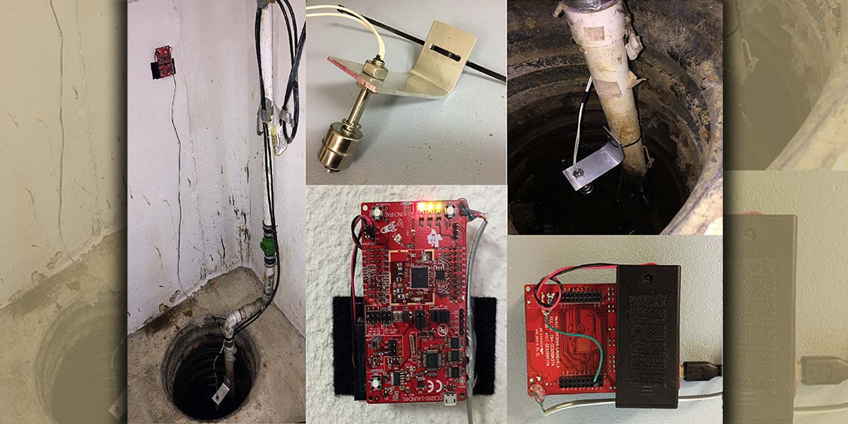
My campaign against infiltrating water began when I moved to a location with a higher water table that required the assistance of a sump pump to keep water out of the basement. This is particularly worrisome during the snow melts and heavy rains of the spring. As every sump pump will one day expire, backup systems are needed to prevent basement flooding. The device I created , the IoT sump pump, (Figure 1 above) provides a first line of defense against a flood. It will alert the user via text message that the water level has risen above the sump pump’s maximum level, thereby indicating a pump failure. This alert could potentially enable the user to return home and drop in a replacement pump prior to any flooding occurring.
Although the device described here will send a text as a sump pump warning, this project applies to pretty much anything with an appropriate sensor. An open door or window, a tripped laser beam, a pressure change on a pressure plate, a proximity sensor, etc., could all be converted into a text message warning.
Project Overview
My goal for this project was to design a device that will monitor the sump pump water level and text me if the water level gets too high.
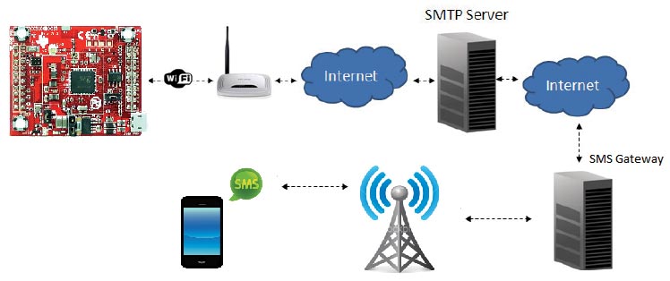
FIGURE 2. Project big picture.
The device design parameters included:
- Must be battery powered
- Have Wi-Fi capability
- The ability to send an email or text
I chose to go with Texas Instruments’ CC3200 LaunchPad, which is the evaluation board for the CC3200 Wi-Fi wireless microcontroller (MCU). LaunchPad comes with a built-in in-circuit debugger, LEDs, switches, sensors, and two 20-pin connectors.
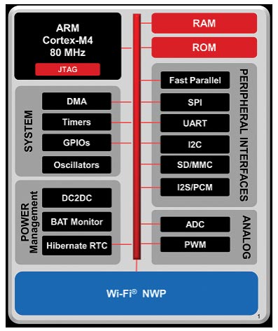
FIGURE 3. CC3200 hardware overview.
For water level sensing, I selected a reed switch commonly used in aquariums. The switch is hermetically sealed in the body of the device, while a magnet is located within the float ring. The bracket for the reed switch was cut from a 1/8 in x 2 in x 4 ft piece of aluminum from a local hardware store.
The entire design runs off two AA batteries. To limit the load current and extend battery life, the device is mostly hibernating. It wakes up immediately if the reed switch closes, and it also wakes up every eight hours to check the battery voltage and read the switch. If it finds that the reed switch is closed or the battery level is low, it will text me to let me know.
Email to Text
To avoid utilizing third-party servers/gateways to send an email or text, I use CC3200 SDK and my Gmail account. The way it works is that on CC3200, I run an SMTP client that connects to my Gmail account. Once connected, it sends an email message to my mobile carrier’s SMS gateway, which sits on the mobile network that delivers the message. All you need is a phone number and an SMS gateway domain name.
In my case, the Verizon SMS gateway domain is vtext.com. So, I send an email to [email protected], where 1234567890 is my phone number. All email and Wi-Fi settings for the project are stored in a config.h file.
Hardware Design
CC3200 is a SoC (system on chip) that consists of an ARM M4F core for application software processing, SimpleLink (the Wi-Fi network processor subsystem), 256 kB RAM, and peripherals. SimpleLink has its own dedicated ARM MCU that completely off-loads the application MCU. It also includes 802.11bgn radio and a TCP/IP stack. This arrangement simplifies development significantly.
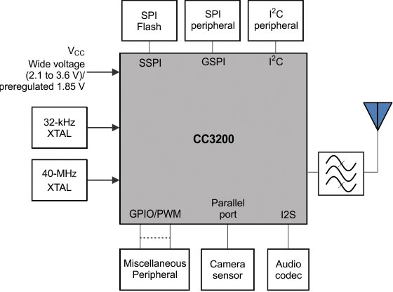
FIGURE 4. CC3200 functional block diagram.
The application MCU runs at 80 MHz. User code and user files are stored in an external serial Flash (1 MB). ROM comes factory programmed with device initialization firmware, a bootloader, and a peripheral driver library. The power-up sequence is as follows: After a PoR (power-on reset), the device gets initialized, then the bootloader loads the application code from the serial Flash into on-chip SRAM and jumps to the application code entry point.
There are only a few minor modifications needed for LaunchPad:
- Add a resistor divider across the battery terminals and connect to ADC (analog-to-digital converter) pin 58.
- Open J2 and J3 so that the yellow and green LEDs are not ON in Hibernate mode.
- Open J13 to supply the board from the J20 battery connector.
- Depopulate R3 to disable the D1 LED.
- Depopulate R20 to disable the D4 LED.
- Connect the reed switch to wake-up input GPIO (general-purpose input/output) #13.
The CC3200 ADC is 12-bit/eight-channel, out of which four channels are available for user applications. The sampling rate is fixed at 16 µs per channel, and the channels are sampled in a round-robin fashion. The pins tolerate a maximum of 1.8V, but full scale is 1.467V.
To keep it simple, I chose to implement a divide-by-two resistive divider. Since this will always be connected across the battery terminals, I went with one meg resistors to keep the current consumption low. The drawback to this approach is that the sampling capacitor current will be severely limited, thereby affecting ADC readings. To fix this problem, I placed a 100 nF capacitor across the lower leg of the resistive divider.
The CC3200 internal sampling cap is 12 pF and is switched on for 400 ns. So, a much larger 100 nF external cap will supply enough current for the sampling cap to reach the final voltage value of the divider in time to get correctly sampled. The simulation in Figure 5 shows the voltage on the sampling cap with and without the 100 nF external cap.
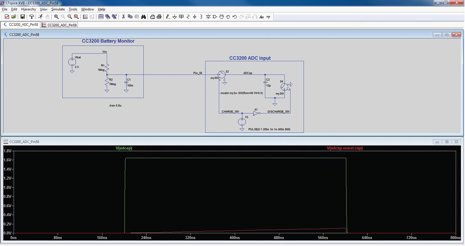
FIGURE 5. Voltage on the sampling capacitor with and without an external capacitor in the voltage divider.
Also, I knowingly compromised the voltage range measurement and bandwidth. This means the ADC input will get full scale when the battery voltage is 2.9V. Also, the voltage change on the pin will be slower. In this application, that didn’t matter since I was only interested in a low point in the battery voltage range. If the battery voltage dips below 2.4V, a text will go out as a warning to replace the batteries.
Assuming two AA batteries (not at full capacity) and an average load current about six times higher than expected, the batteries should last well over a year: 2,000 mAh/0.1 mA = 20,000h ~ 833 days.
Whenever the reed switch input is sampled, it’s also debounced. The pin is pooled every 10 ms, 100 consecutive times. Only if it reads “1” every single time will it return “success.” This will prevent a false alarm.
To preserve the batteries, the device is kept in Hibernate mode. In this state, most of the SoC is powered down except the RTC (real time clock) and 2x32-bit OCR registers.
Before hibernating, the software enables two wake-up sources: RTC (every eight hours) and GPIO #13. The reed switch and LaunchPad switch SW3 are both connected to GPIO #13. Upon wake-up, the core resumes its execution in the ROM bootloader. While hibernating, the measured current out of the battery was close to 8 µA.
Software Design
The software development was done using Code Composer Studio (CCS): a free integrated development environment (IDE) with a compiler/debugger. CCS is a very powerful tool, but it takes some time to get to know it. There are lots of videos on CCS on the web, so I won’t go into details on how to use it here.
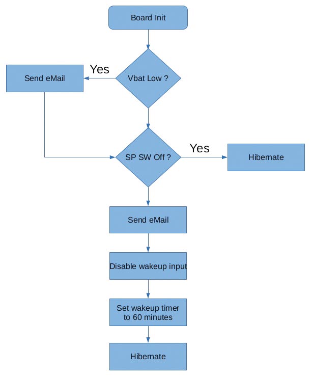
FIGURE 6. Code flow.
CC3200 has three SOP (Sense On Power) pins. The state of these pins defines what mode CC3200 will be in after power-up. SOP[2:0]=0b000 instructs the bootloader to load the application from the serial Flash to the internal MCU RAM. SOP[2:0]=0b100 instructs the bootloader to enter “download” mode. This mode is used to program the application to the serial Flash. This is done with the help of a UniFlash tool.
Once the image is programmed, J15 can be removed and the board reset. At that point, the application code is going to get loaded from the serial Flash to SRAM and executed. During development/debugging, I have J15 on (SOP[2:0]=0b100), which will keep the bootloader in “wait” mode so the application won’t be automatically running.
The application is non-OS based. The logic is very simple and robust, which keeps code to a minimum but still accomplishes the objective. Also, I used CC3200 DriverLib as much as possible and all the DriverLib calls are linked to ROM (functions with “MAP” in prefix). The main function initializes the board, reads the sensors, sends an email if needed, and goes into hibernation when done. Every time the device wakes up, it goes through the same routine.
The first thing the application will do is initialize the board. This takes care of setting up the ports and pins, UART, and Hibernate mode. Next, it will check the battery voltage level. If the battery voltage level is low, the application will send an email warning. It will also read the reed switch. If the switch is off, the board goes into hibernation.

FIGURE 7. Code Composer Studio 7 IDE debug session.
The board will again wake up in eight hours (or on a closed switch). However, if the switch is on, the application will send an email, disable wake-up input, and set the timer to wake up in 60 minutes. This will avoid email bombardment.
If the sump pump gets fixed by the time the board wakes up, then everything continues as if nothing happened, and the board goes into hibernation for the next eight hours. However, if the sump pump reed switch is still on, an email goes out again.
If everything goes right with the AP connection and an email gets sent, all three LEDs will turn on before hibernation. If there is a problem with the connection to the AP, an orange LED will flash. If there is a problem with sending an email, a green LED will flash.
Additional Considerations
An SMTP client is part of CC3200 SDK, and it will create a socket, connect, authenticate, create, and send packets to an SMTP server for you. I won’t go into details on how the SMTP protocol works here, but there is an excellent “Email” example included with SDK. Also, you should check out the original SMTP spec created in 1982, RFC 821.
Needless to say, you’ll need a Gmail account. You must set your username, password, phone number, and your AP access parameters in the config.h file. In addition, you may have to change your Gmail account settings and enable access for less secure apps. Also, I have my AP on a battery backup unit in case of a power outage so that I can still get warnings.
This project was done using CCS 7 and CC3200 SDK 1.2. Necessary files for this project are available in the article downloads or at https://github.com/mkolakovic/IOTSumpPump. You may need to change project settings and redefine paths to your CCS and SDK libraries. All development software is free, available for download, and without limitations.
Now for the real world problems: Try not to place the board too close to the pump power cable because EMI generated by the pump motor and radiated from the power cable could interfere with the board. If you must install it closer, the input debouncing is robust enough to function. The worst that can happen are false wake-ups affecting battery life. This assumes you have no issue with Wi-Fi in the installation location. You could try putting the board in a metal enclosure, but then you’ll need a whip antenna (that would be just fine).
Another issue is running the reed switch cable in parallel and next to the power cable. This could cause high voltage transients from the pump power cable to couple to the reed switch cable. Since there is no TVS on the CC3200 reed switch input, transient could potentially damage the SoC. A TVS on the reed switch input is something I will definitely be adding to this project.
So, go ahead and see a movie or meet a friend for coffee, even if it’s pouring outside. Because if your pump decides to go kaput, you’ll get a text warning and will be able to keep all the awesome stuff that you’ve got in the basement safe and secure. NV
Parts List
Texas Instruments CC3200 LaunchPad
www.ti.com/tool/CC3200-LAUNCHXL#buy
Uxcell DC100V 75 mm stainless steel float switch
https://www.amazon.com/gp/product/B01LZ098GO/ref=oh_aui_detailpage_o01_s00?ie=UTF8&psc=1
Enclosed two AA battery holder
https://www.radioshack.com/products/radioshack-enclosed-2-aa-battery-holder
Capacitors: 10 nF and two 100 nF
Resistors: 1K ohm and two 1 mohm
1/8 in x 2 in x 4 ft piece of aluminum bar
Velcro™ and zip ties
References
https://www.ti.com/product/CC3200/pdf
https://en.wikipedia.org/wiki/SMS_gateway
http://processors.wiki.ti.com/index.php/CC32xx_Email_Demo_Application
https://www.ietf.org/rfc/rfc2821.txt