When I started this project, my main goal was to build a laser harp from scratch. I had heard of them and even built a simple 10 note version from a kit. What I wanted to design, however, was a harp covering five octaves utilizing an off-the-shelf concert type of keyboard. This would give the harp range coverage and capabilities of instrument selection, plus it would be MIDI compatible.
Overall Design Summation
As I began my design, I realized the average harp only had about 35 strings. This arrangement covered five octaves, but only had the basic notes available (A, B, C, D, E, F, and G). The incorporation of flats and sharps were accomplished by mechanical means. So, my initial design had the equivalent of 60 notes: A, A#, B, C, C#, D, D#, E, F, F#, G, and G#. In the language of music, an A# (sharp) is the same as a Bb (flat), etc. There is only a half note separation between B and C and again for E and F. So, a B# (sharp) is really a C and a Fb (flat) is really an E. Finally, 12 notes per octave times five octaves equals 60 “strings.”
In a normal laser harp, each string is replaced by a 5 mw laser. I realized very early that a musical instrument utilizing 60 5 mw lasers would be problematical to align, not to mention the obvious safety concerns. Therefore, I decided to use an LED strip as the light source, The name LED harp just didn’t sound exciting, so I decided to call this a lambda harp since lambda is the Greek letter assigned to a wave form’s wavelength.
The basic design premise here is each “string” is replaced by a light source (the LED strip), a CdS photocell, and an accompanying circuit that monitors the state resistance of the photocell. In other words, each string is now the equivalent of a photoelectric burglar alarm.
When the light beam is interrupted, the photocells change in value which is the equivalent of a key on the keyboard being pressed, thus producing a specific note.
Circuit Description
On a MIDI keyboard, when a key is pressed, a membrane switch is usually contacted letting a current go through it, resulting in a musical tone being heard through the organ speaker. In more sophisticated keyboards, pressing a key actually results in two membrane switches being contacted, one before the other (see Figure 1).
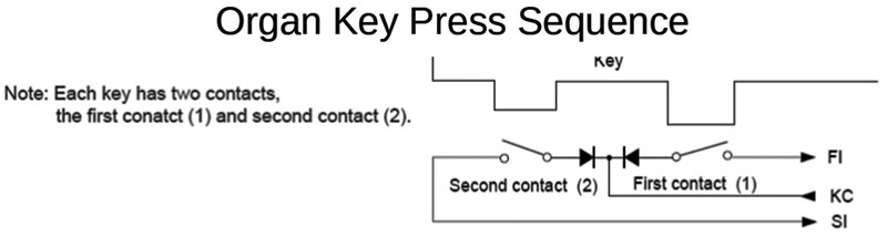
FIGURE 1. Organ key press diagram.
Measuring the time between the first membrane contact and the second membrane contact is interpreted by the organ circuitry as to how hard the key was pressed, resulting in the loudness of the resulting tone.
This second example is the description of the keyboard I used. Basically, I paralleled the connections across these membrane switches to interface my wheel circuitry with the organ membrane switches. For reasons of simplicity and circuit protection, this design used relays — those components from the last century that are not solid-state.
Looking at Figure 2, you can see the basic photocell circuit that I used.
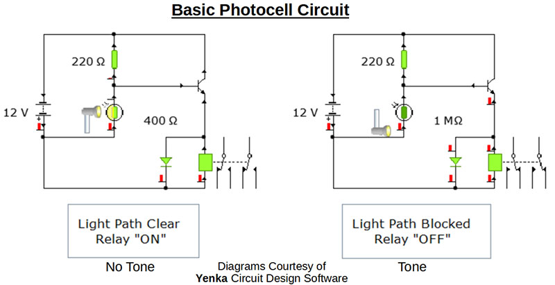
FIGURE 2. Yenka photocell evaluation circuit.
The left example shows the relay state as “ON” when the light beam is clear. The right example shows the relay state as “OFF” when that same light beam is blocked.
The relay contacts are wired such that an ON relay (unblocked light beam) means the membrane switch is NOT contacted, resulting in no tone being generated; a blocked light beam results in a contacted membrane switch, so a tone is being generated. This is accomplished by my connecting the membrane parallel wires to the NC (normally closed) contacts of the relay, thus simulating a typical alarm circuit.
Operationally, the 220 ohm resistor and the photocell form a voltage divider, the center of which is connected to the base of the 2N3904 driver transistor. While the photocell is sufficiently lit by the LED strip, the base voltage is high enough to bias the transistor to an ON state, allowing current to pass through and thus turning on the relay.
When the photocell illumination is interrupted, the base voltage is pulled low by the 220 ohm resistor, resulting in the transistor turning OFF, thus turning off the relay. The 1N4007 is placed in parallel with the relay coil so that when the relay turns off, the inductive voltage spike created by the relay coil’s collapsing magnetic field doesn’t damage the other components of this circuit.
Wheel Design Summation
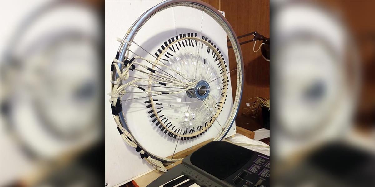
Instead of the normal shape of a harp, I decided to incorporate a circular structure (see Figure 3, Photo 1).
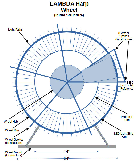
FIGURE 3. Wheel; basic structure with spokes.
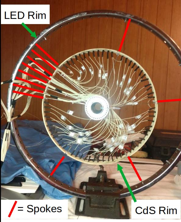
PHOTO 1. Partial wheel.
This would make the instrument more compact for playing and moving. For the base component of the circular structure, I selected a bicycle wheel. The initial benefits are the wheel’s strength and uniformity of shape. The most important reason, however, is the wheel I chose has 72 spokes. This means that strategically removing the 60 spokes needed for the light paths left 12 spokes to maintain the shape and structural integrity of the frame.
By starting with eight spokes in sequence then removing 12 spokes, I’ve created the space for the first octave. Next, I kept one spoke for structure and removed 12 spokes to complete the second octave.
Repeating this three more times gives us our five octaves, ending with the first of the original set of eight spokes (refer again to Figure 3, Photo 1). Continuing on, I positioned the first of the eight-spoke sets as a horizontal reference, marked HR. Going in a clockwise direction, the first 12 light paths are designated as 1-12. Then, a structural spoke and the next 12 light paths are designated 13-24.
Completing the pattern is the next spoke for light paths 25-36, the spoke and light paths 37-48, one more spoke, and finally the light paths 49-60.
This ends at the start of the first eight-spoke set. Paying attention to the keyboard (see Figure 4), the lowest note on the far left (a C) is referenced as note #1.
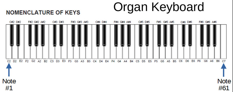
FIGURE 4. Organ keyboard.
Moving to the right across the keyboard (counting both white and black keys) they end at the far right (the highest note, a C) which is note #61. I only utilize up through note #60. These numbers correlate exactly with the light path numbers on the wheel.
Along the inside of the wheel rim, the LED strip is positioned facing inward. I should mention at this point that the wheel I used is for a 26 inch bicycle. The actual reality is the wheel’s outer rim diameter is only 24 inches. That resulted is some confusing moments in that I had expected a 26 inch bicycle wheel to be 26 inches in diameter, not just 24 inches. It turns out, a wheel diameter includes the tire.
Next, I inserted a 14 inch diameter thin wood cylinder co-axially inside the wheel. I used a quilting hoop as it seemed the best choice for ease of construction.
On this inner cylinder, I mounted the 60 CdS photocells facing outward, aligned with each incoming light path.
Hoop Design Summation
Using a 72 spoke bicycle wheel means that the spokes have a five degree separation as they radiate outward from the hub to the rim. The circumference of this hoop is calculated by: C = Pi*D where C = circumference; Pi= 3.1416 (approximately); and D = the diameter of the hoop. In my case, C = 3.1416*14 inches = 43.98 inches, which I rounded up to 44 inches.
Make a strip of paper whose length is equal to the circumference of the hoop. Divide this length by 72 (the number of spokes on the bicycle wheel) to give a spacing between marks on this strip of paper representing the intersection point of each spoke as it travels from hub to rim on the bicycle wheel.
Next, mark a corresponding start as HR and step mark by mark in the same order. This gives us the scaled down positions on the hoop correlating to the same positions on the bicycle wheel rim. Repeating, we have now marked the HR (the last of the eight structural spokes), then the mount positions for CdS cells 1-12, another structural spoke, positions for CdS cells 13-24, etc., ending with positions for CdS cells 49-60. The remaining seven marks are the positions for the last seven structural spokes of the eight-spoke set.
Taping this strip to the outside of the hoop gives you the template for the CdS photocell mounts, their pass through holes for one wire of each photocell, and the 12 pass through holes for the structural spokes. The second wire of each photocell is connected together as a common signal ground.
To insure that each photocell would respond to its own radially incident light path, I mounted a piece of 1/4 inch diameter by 1/2 inch length heat shrink tubing around each cell position, facing outward. Photo 2 gives an easier way of seeing these heat shrink light funneling tubes I mounted over the photocells.
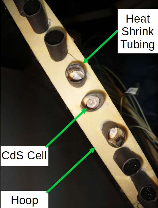
PHOTO 2. CdS photocell mounting rim.
Referring to Figure 5, it shows the wire routing paths I used for both the LED strip and the photocell circular array.
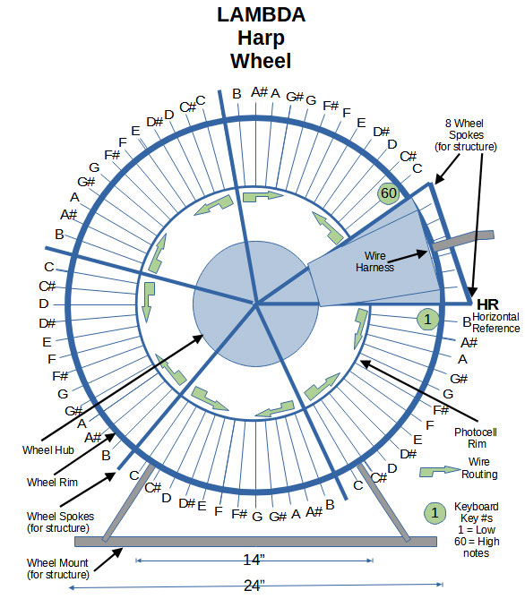
FIGURE 5. Wheel; complete structure diagram.
I then mounted the wheel to a wood base for stability. Photo 3 shows you the completed wheel.
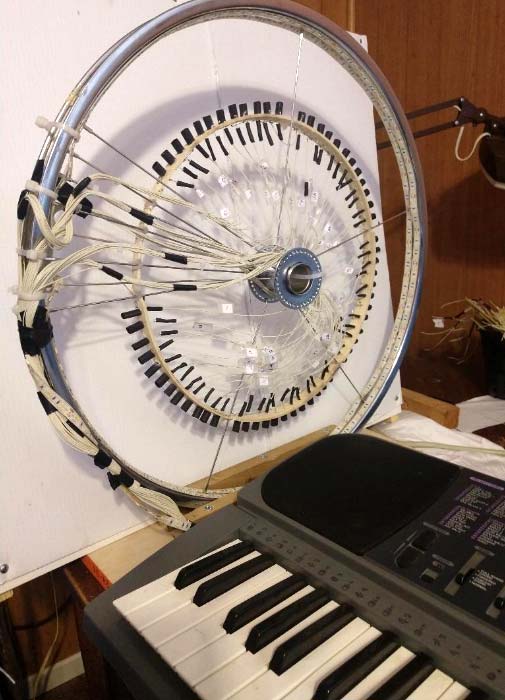
PHOTO 3. Completed wheel.
Making the Wheelbase
For simplicity and ease of construction, I made the wheelbase out of wood. Depending on the aesthetics you wish, the choice of wood to use will be obvious.
The assemblage and dimensions are shown in Photo 4.
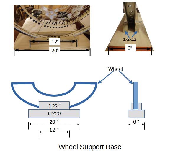
PHOTO 4. Wheelbase construction.
This design gives the wheel the stability it needs for playing.
Connecting the Wheel to the Organ
I designed a printed circuit board (PCB) to mount all of the interface circuitry on.
Figure 6 represents a part of the PCB circuitry.
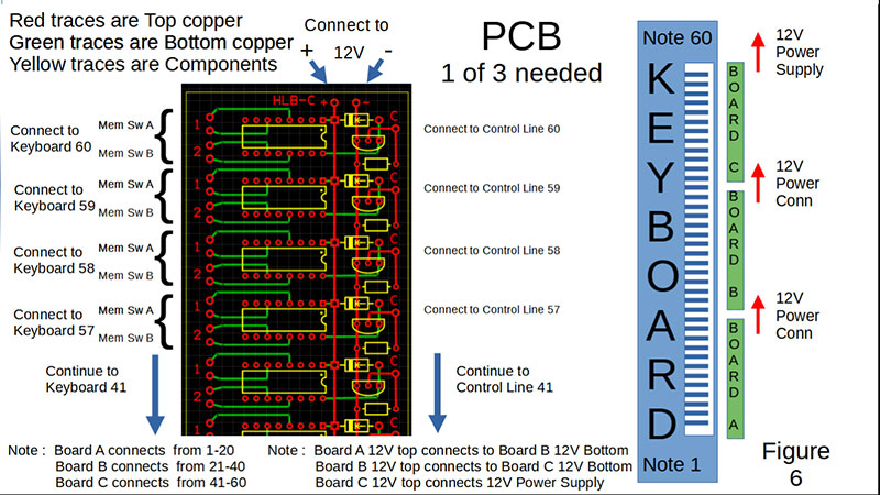
FIGURE 6. PCB layout and keyboard relation.
This basic single relay circuit is replicated 20 times per board, meaning three boards are needed to complete the project. Photos 5 and 5A are of the finished harp PCB.
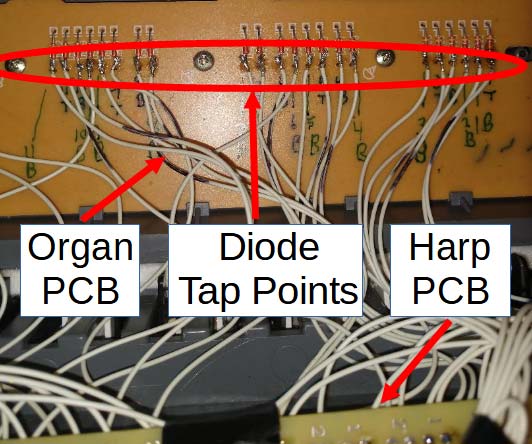
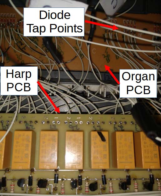
PHOTO 5 and 5A. Harp PCB.
Each relay on the board is a DPDT relay (Figures 7 and 7A), thus handling the two membrane switches needing to be closed simultaneously.
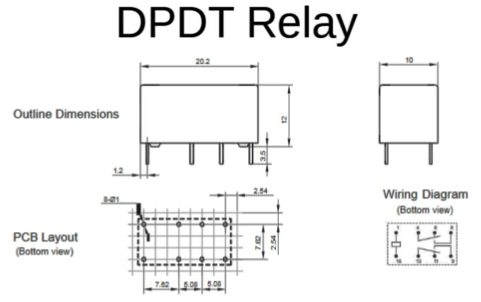
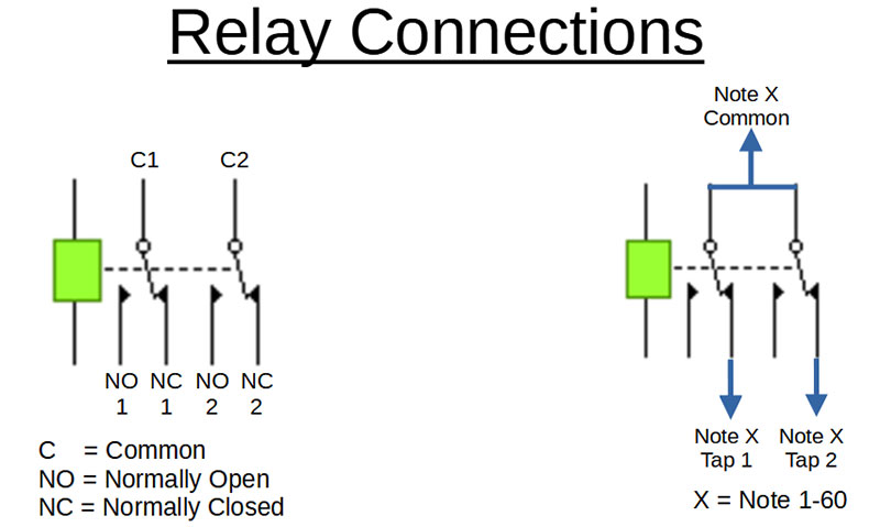
FIGURE 7 (top) and 7A. DPDT relay diagram and pinout.
This action is interpreted by the keyboard as a hard keystroke.
After reverse-engineering the keyboard’s PCBs, I determined the best place to parallel off the membrane switches (Figure 8, Photo 6) was the organ key switch isolation diodes.
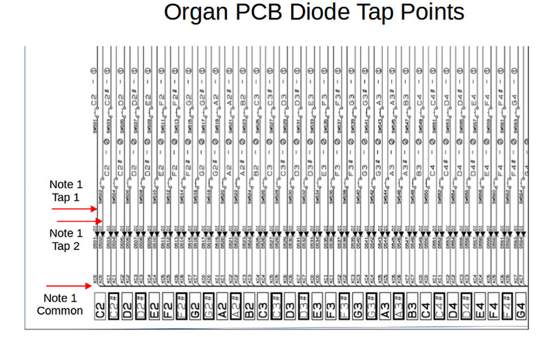
FIGURE 8. Organ PCB diagram showing diode tap points.
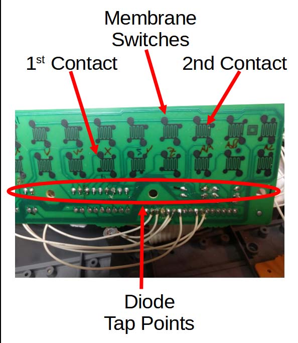
PHOTO 6. Organ PCB.
Under the keyboard with the access panel removed, I found exactly the amount of space I needed to nest the three PCBs. Actually, I measured it before I designed the boards.
Anyway, after much soldering, mounting the components on the PCBs, and using 24 gauge Teflon jumper wires, the installation was complete. NOTE: It’s very important that the interface boards be activated BEFORE the keyboard is turned on. No damage should occur, but it might result in a loud sound pulse.
Also, the LED strip I used was long enough to circle the wheel twice, insuring enough light for the photocells. I still had enough length left over to wrap around the front of the keyboard to make it sort of flashy looking.
With the keyboard I used (a Concertmate 990), this device has over 160 instruments, percussive, and synthetic sounds available. And, of course, all of this is MIDI compatible. Have fun! NV
Parts List
| Name |
Qty |
Description |
Notes |
| Q1 |
60 |
Driver Transistor |
2N3904, TO-92 Case |
| R1 |
60 |
Pull-Down Resistor |
220 ohm, 1/4 watt, 5% |
| D1 |
60 |
Protection Diode |
1N4007, 1000V, 1A |
| CdS |
60 |
Photocell |
X002HL7LHV |
| Relay |
60 |
DPDT Relay |
HK-19F-DC12VX002HL7LHV |
| LED |
1 |
LED Strip |
Flexible, 300 units, SMD 5050 |
| PS |
1 |
Power Supply |
5V, 3A, 15W AC/DC Adapter |
| PCB |
3 |
Printed Circuit Boards |
ExpressPCB.com |
| Wire |
|
Connection Wire |
I used #24 Teflon Wire |
| WHeel |
1 |
26 inch dia Bicycle Wheel |
I used a 72 spoke Large Hub Wheel |
ACKNOWLEDGMENTS
Circuit Design/Simulation Software: Yenka
Circuit Board Design/Fabrication Software
- ExpressPCB
Drawings/Diagrams/Pictures: LibreOffice
Downloads
What’s In The Zip?
Video
PCB Files