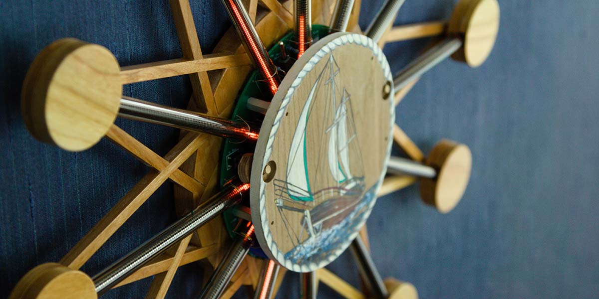
The NixieStar clock is the second timepiece kit I’ve developed. My aim was to have a kit that’s reasonably easy to build with intermediate soldering skills (i.e., minimal SMD components). I also wanted a clock kit that once it was built, any spouse (including my wife!) would accept it on their wall — even with a power cord hanging from it. The clock can be built in either 16 inch or 14 inch diameter versions, depending on the Nixie bar graph tubes used.
While my first kit was a geekier design using technology for the clockworks to be more in line with those of the tubes, this design is meant to be more elegant and have a more intricate case. It still uses an ATmega328 from Atmel for its processor, as well as the Maxim 1771 IC for the power supply.
The two surface-mount components are the real time clock (RTC) IC that does the actual time keeping and the 12-channel digital-to-analog converter (DAC) for driving the tubes. It sports a 15F capacitor for maintaining the time when there is no power. Once fully charged, the capacitor will keep the time for a month or two with no power.
Because the clock only has 12 hands (tubes), to determine the exact minute that the clock is on takes counting the blades on the ‘propeller,’ which is comprised of short segments that rotate around on the 12 lamps. There can be one, two, three, four, or six blades lit; these indirectly indicate the number of minutes past the five-minute mark indicated by the long hand.
One blade is for zero minutes; two is for one minute; three is for two minutes; four is for three minutes; and six is for four minutes past the five-minute increment. Figure 1 gives a visual representation of this.
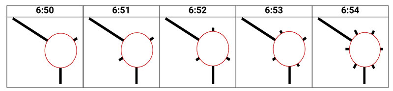
FIGURE 1. Reading the minutes on the clock.
There are two buttons and one switch used to set the time. The switch that is located between the 11 o’clock and 12 o’clock hands will move the time either forward or backward one hour with each toggle. The time will be moved forward if the switch is toggled toward the 12 o’clock hand and moved backward one hour if the switch is toggled toward the 11 o’clock hand.
Finer control on setting the time is provided by the two buttons on the face. The left button (while pressed) will advance the clock forward one minute every second or so until it’s released. The button on the right side of the clock will advance the clock forward 10 minutes every second until it’s released. Finally, if both buttons are pressed simultaneously, the clock will be paused until they are released.
Circuit Description
The clock can be divided into five main sections:
- The low and high voltage supplies.
- The CPU with its switches.
- The RTC.
- The 12-channel DAC.
- The Nixie bar graph tubes and their drivers.
Figure 2 has the schematic CPU portions of the clock which encompass the first four sections.
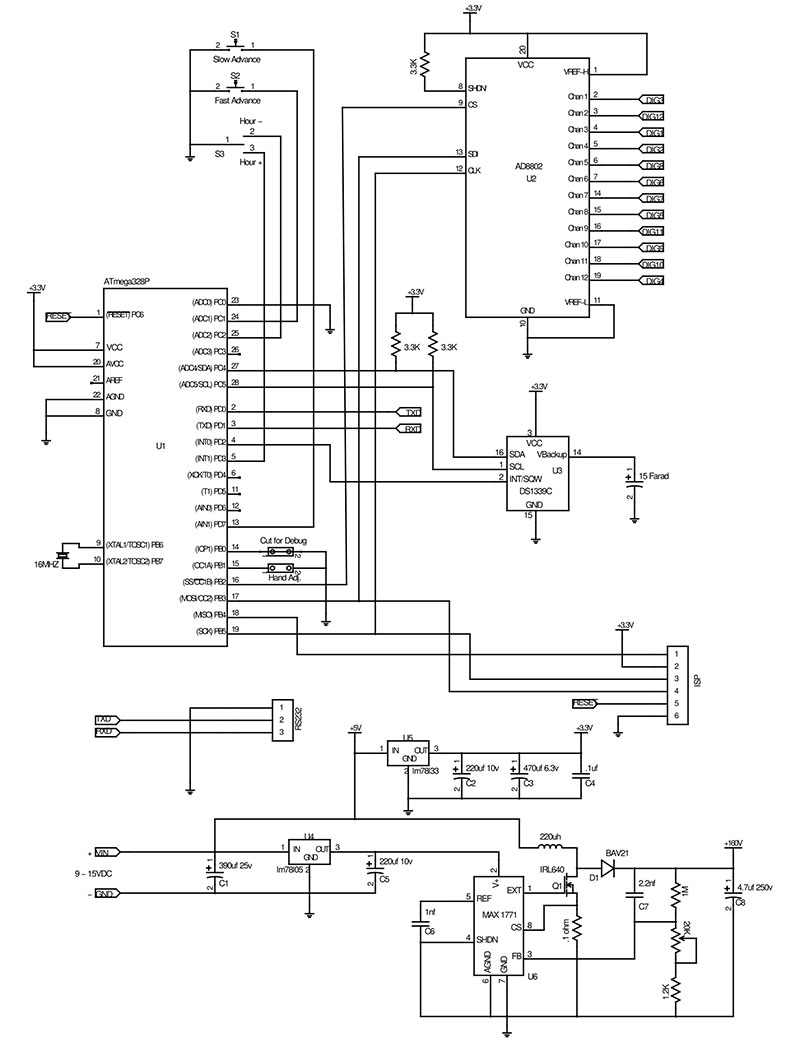
FIGURE 2. CPU schematic.
Figure 3 shows section 5 (the 12 tubes and their drivers).

FIGURE 3. Nixie bar graph and driver schematic.
The low voltage supplies are simply a single LM78L05 or LM78L33 linear regulator which reduces the 12V to 5V and 3.3V, respectively. The high voltage supply is a switching boost supply comprised of a MAX1771 IC and associated parts to generate the 150V needed to drive the Nixie tubes.
The Maxim 1771 operates by effectively shorting the 12 volts DC to ground through the coil L1 using the MOSFET Q1. When it turns off Q1, this releases the coil from ground and a large positive spike is generated, which is then stored in electrolytic capacitor C8. Diode D1 keeps the capacitor from discharging back through the circuit.
The 1M, 1.2K, and 20K potentiometer in parallel with C8 form a voltage divider which feeds a small voltage back to the Maxim IC so that it can adjust the pulse’s frequency and duty cycle to regulate the voltage. Capacitor C1 provides a large enough well of energy to help keep the voltage high enough for the low voltage supplies as the MOSFET shorts the coil to ground.
The CPU portion handles the switches which allow you to set the time, as well as feed the correct values to the DAC that drives the tubes. Notice there’s a hand adjust jumper. This jumper will force the clock into a mode where it drives each tube one at a time at full length.
This has two effects. When the tubes haven’t been operated for a long period of time, they need to be driven for a while before they will illuminate their full length. It also allows you to step the length of each tube’s length, so they are reasonably equal. This process is described later in the article. The debug jumper — when cut — allows debug messages to be sent out of the serial port.
The 12-channel DAC is driven through the SPI bus of the processor. It provides 12 eight-bit DACs (one for each tube) that can be individually set. Once a channel’s value is set, that channel’s analog value will be maintained until a new value is set.
The RTC is controlled through the I2C bus of the processor. It provides a trickle charge to the super cap to keep it fully charged for when it’s needed. The IC has an onboard crystal which makes it pretty accurate. Over a year, it should be within five minutes.
This IC also provides a 32K kHz signal that’s used as the time base for the processor (not the system ‘clock’ which is driven at 16 MHz). All the timers within the code are based off the signal from the RTC.
The Nixie bar graph tube and driver are very simple. The tube itself has two or three pins depending on size. The larger tube has three pins. Pin 1 is the anode; pin 2 is the cathode on the larger tube; and pin 3 is an auxiliary cathode.
The tube is driven by always having 160V on the anode, then pulling the cathode to ground through a resistance. A transistor is used to vary the resistance and hence the amount of current that flows through the tube. The higher the current, the longer the segment of the cathode is illuminated.
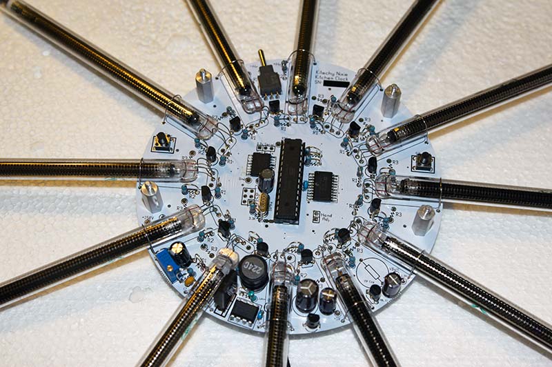
Circuit board.
The auxiliary cathode of the longer tube is used to help ensure that the cathode will always start glowing at the bottom of the tube. With the shorter tube, they use different metals in the cathode to help persuade the cathode to start at the bottom. With either tube, you must treat them kindly or the cathode will not glow where you want it to.
The first rule is to not make drastic current changes on the cathode. It’s best to step the current up and — more importantly — down at a steady pace. The second rule (for the shorter tube) is that you never completely turn it off because it may not turn back on if you just want a short segment lit.
The code for the processor is basically a large loop. It checks for the switches to be activated and if they are, deal with the time as needed. If no switch activations are detected, it then reads the time from the RTC if needed and sets the hands accordingly.
One of the biggest issues I had with this clock was noise generated by the high voltage power supply getting onto the 3.3V logic supply. This greatly interfered with the operation of the RTC (which is a bit fussy about this). A proper layout of the power supply would have probably helped, but there were space limitations for this.
The two steps I used to help combat this was the classic: Put a bigger capacitor on it. The first was to place a big capacitor before the coil of the HV power supply. This helped ensure that when the coil was shorted to ground, there was enough energy to not put a giant dip in the voltage to the low voltage regulators. The second was to put a large capacitor very close to the processor and clock chip to help ensure that they always had reasonably clean power feeding them.
This board contains parts which must be installed in a certain direction. The electrolytic capacitors must have the positive lead (typically, the long lead) inserted into the hole with the square pad. Not all the electrolytic capacitors have a square pad for the positive lead. Be sure to look for the pad marked with a + symbol on the silkscreen to put the positive lead into. There are always + symbols by the pad for the positive lead of the electrolytic capacitors.
Diodes must have their cathode inserted in the square hole. The cathode side of the diode has a stripe painted on it. The transistors and the regulator have their outline silkscreened on the board. Be sure to orient them correctly. Pin 1 of the CPU has a square pad. You need to rely on the silkscreen to show the orientation of the two SMD ICs. Putting in any of the parts backwards will cause the clock to malfunction and most likely damage the component and/or the clock.
Construction
First, the obligatory warning! This clock uses 160 volts which is present on the board. Handle the board carefully! I typically only manipulate the board by its edges once it’s separated from its ‘outer square.’
The kit assembly manual is included with the downloads for this article. It’s more detailed and has many helpful drawings that you can refer to.
The printed circuit board (PCB) assembly is pretty straightforward. I start by building both the low and high voltage supplies and making sure they’re working. I then place the two surface-mount chips. These are reasonably easy to solder. I place a light coat of solder on two opposing corner pads for each IC, then set the chip on top and heat one of those corners until the solder melts.
I'll adjust the chip so it’s properly aligned and heat up the other corner. I then proceed to solder the remaining pins. Remember, it takes just the tiniest bit of solder for each pin.
After soldering each IC, I inspect them with a magnifying glass to ensure the pins are all properly soldered and there are no shorts.
After those ICs are placed, I install the remaining components for the processor. This includes the 1.1 µF capacitor, the crystal, the electrolytic capacitor, the two ‘Hand Adj’ pins (which should be placed on the back of the board), and the three 3.3K resistors.
The next parts to install are the three switches. After these, I install the three sets of 12 resistors (clocks with the IN-9 tubes only have two).
The tubes are the last pieces to be installed. It’s important to ‘loop’ the leads of the tubes as shown in Figure 4.
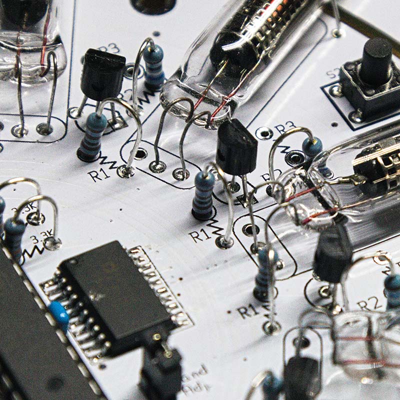
FIGURE 4. Mounting the Nixie bar graph tubes.
This allows the tube to be moved about when mounting it in the frame. If the leads are too taut when soldered to the board, the tubes will crack and be ruined. The photo shows the smaller tube which only has two pins. This is to help you see which two holes should be used.
For either tube, the silvered side of the tube should be down facing the board. You should be able to see the ‘cage’ around the wire when looking down at the component side of the board.
The case construction is a bit more involved. This case is my first foray into using a CNC machine. Talk about learning new skills! Fortunately, I found a nice compiler of sorts that accepts a C like language and creates a G-code, SVG, or DXF file.
With the case being very geometrical, this worked well. It allowed me to use my programming skills to tell the CNC what to do. That just left learning how to make a CNC cut a pattern from wood repetitively. (My family enjoyed a few evenings in front of the fire pit outside disposing of the chopped trees I slaughtered in the process!)
The tree massacre was worth it! Not only did I learn a lot about working with wood and the CNC, but I can now cut out all the pieces to a case with my CNC in just a couple of hours.
The pieces of the case come on five boards in the kit. Care must be taken when handling the boards and removing the pieces from the board. The pieces are held in place on the board by small tabs. If they’re not cut, the wood can break accidentally and blemish a surface. The pieces must be cut with an Xacto™ or similar knife to keep them pretty.
Start by separating the base and the sticks. Remove the tabs on the sides and lightly sand as needed. DO NOT OVER SAND the sticks! If you sand too much, the sticks will fit sloppily into the slots on the base.
Be sure to test that the sticks will fit snugly (but not too snugly!) into the base (DO NOT GLUE YET). Join the pairs of sticks (a short stick and a long stick) into little crosses with a small dab of glue at the joint between the two. Refer to Figure 5.
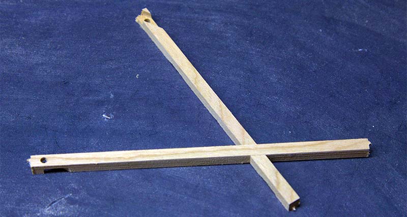
FIGURE 5. The wood crosses.
They are at 60 and 30 degree angles, so the crosses are a little odd.
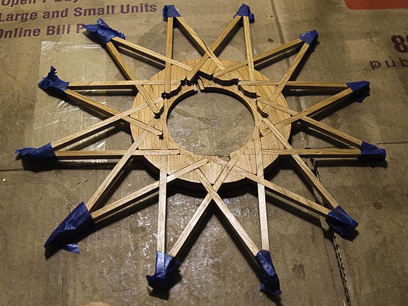
After all the sticks are joined together, they can be glued on to the base (Figure 6).
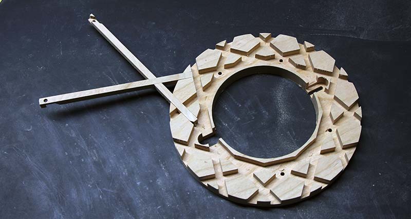
FIGURE 6. Mounting the crosses on the base.
The smallest stick fills in the open section of the clock on the opposite side of where the short stick butts into the long stick (Figure 7).
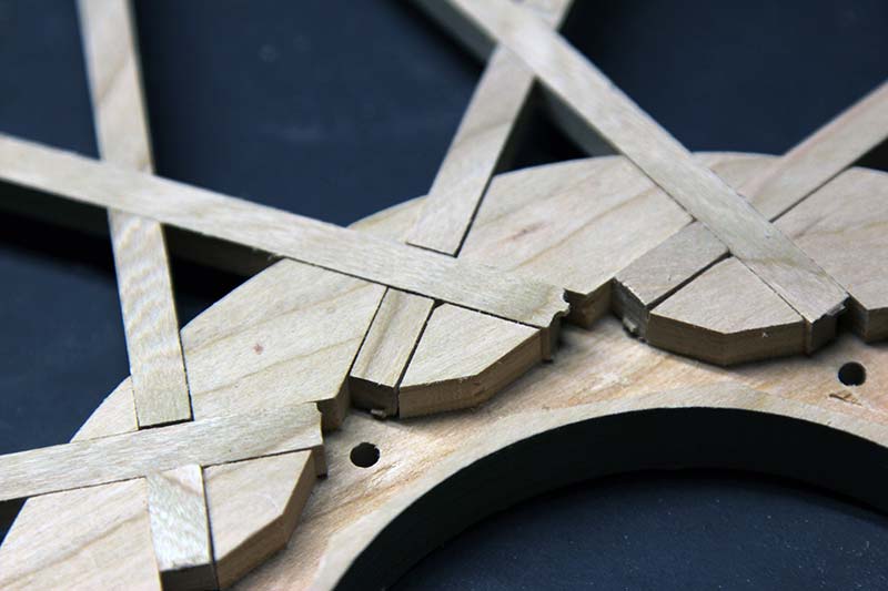
FIGURE 7. Placing the smallest stick.
It doesn’t take much glue to hold the clock together. Only put a small amount of glue in the slots (not on the sides!) of the sticks to help ensure that glue doesn’t get onto the top surfaces of the sticks or the base.
Once the glue hardens, you can then sand the top of the base and sticks with 220 grit or finer paper to help smooth the surface. Be sure to sand as close to the direction of the grain as possible. With the 30 and 60 degree angles of the sticks, you can only approximate this.
Apply the finish you’ll be using to the base and the sticks. Be sure to not put any finish on the last inch of the length of the sticks that form the points. These will have wood glue applied to them which will not adhere well to the finish.
Next, we turn to the circles. Carefully cut out each of the 24 circles. Separate the tops from the bottoms. You can tell them apart by the bottom circles having a hole in the center that passes through them entirely. You need to cut small 1” to 1-1/4” segments from the ribs that were between the sticks and glue them to the bottoms (the side without the slot) on the bottom circles as shown in Figure 8.
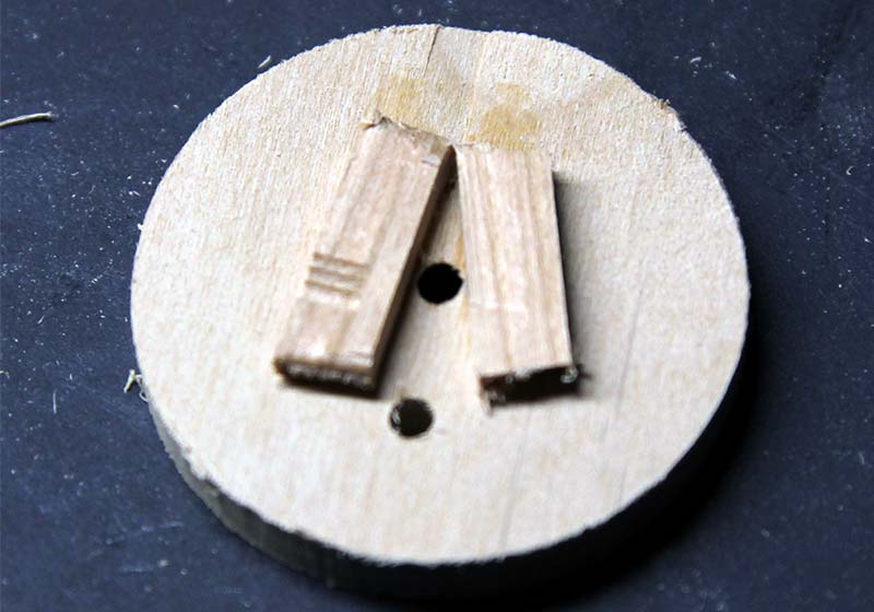
FIGURE 8. The bottom side of the bottom circle with the wood pads installed.
Apply a single coat of finish over the entire piece except for the bottoms of the two pieces of wood you glued to the circle. These are the surfaces that will be glued to the sticks above.
Cut the dowels into 1/2” segments, then glue each segment into the hole in each of the top circles (Figure 9).
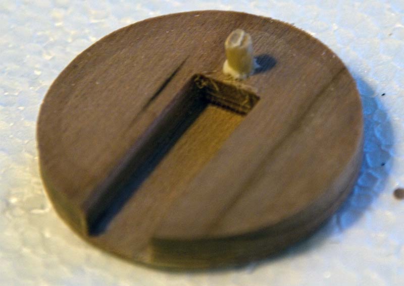
FIGURE 9. The bottom of the top circle with the peg installed.
Once the glue hardens, sand the tops of the top circles with 220 grit or finer paper. Only sand in the direction of the grain.
Once the glue hardens, apply your finish to the circles. There are no surfaces that you will be gluing on these pieces.
Now, glue the bottom circles to the points of the star by cutting small segments from the remaining dowels about 5/8” each; put some glue on the tip and put it into the top of the tip of the star. Then, apply glue to the small pieces of wood glued to the bottoms of the bottom circles and press it on to the star, having the small dowel passing through the hole in the circle.
Be sure the slot in the circle is facing up. Be very careful to ensure the slot is facing exactly to the center of the star and is flat to the plane of the star. If they are not, it will be obvious once it’s complete. Wood glue is very unforgiving, and you will not be able to fix them once the glue hardens.
The final sub-assembly that needs to be put together is the face. Start by sanding it with the grain using 220 grit or better sandpaper. Apply your finish. Do not let the finish build up in the ‘wells’ for the pushbuttons on the front of the face.
Next, screw the four long standoffs into the small holes on the backside of the face using a nut driver. Refer to Figure 10.
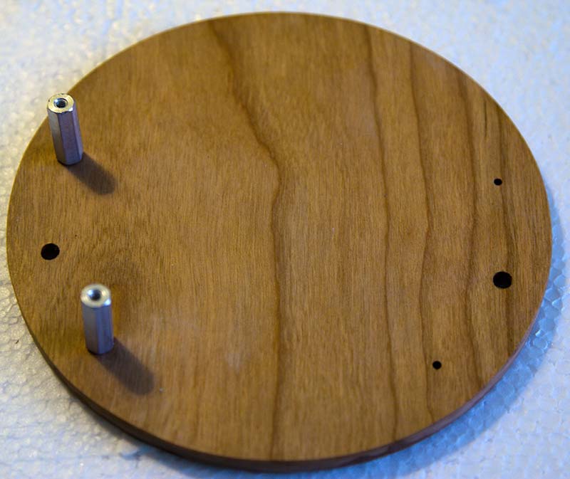
FIGURE 10. The face with two of the four standoffs installed.
Once everything is done to your liking, it’s just a matter of putting all the completed pieces together to finish the clock.
For the 16” clock, put the tops of the wood pieces for pushbuttons through the large holes on the back of the clock. Set the assembled clock PCB face down onto the standoffs. Be sure to line up the holes. Now screw the short standoffs through the holes in the PCB and into the long standoffs. Place this whole assembly — small standoff down — onto the base, being sure to align the short standoffs with the holes in the base. Insert the 4/40 screws into the back of the base to secure the clock to it.
For the 14” clock, the only difference is that you will not use the short standoffs. You will instead use the long 4-40 screws supplied and thread them through the base, then the PCB, and then screw them into the long standoffs on the face. Don’t forget to keep those pushbuttons in place! It’s a bit trickier, but it can be done.
Set the clock on a flat surface face up. Make sure all the tubes are aligned in the slots of the circles and that the tips do not go past the slots. Press-fit the small sticks on the top circles into the bottom circles (DO NOT GLUE) and you are done!
Completed frame.

Completed clock.
Burn In
The Nixie bar graph tubes need time to burn in to light to their full length when they aren’t used for extended periods of time. To do this, put the jumper across the two time adjust pins. This will light each lamp (1 through 12) the full length one at a time. I let the clock sit running overnight like this.
After they’ve reached their full length, they can then be adjusted by leaving the jumper in place and using the two buttons on the front of the face and the switch. The right button will stop the sequencing of the lamps and will move the hand forward one lamp for each press.
When the lamp you want to adjust is lit, you can toggle the switch toward the 12 o’clock hand to lengthen the hand and toward the 11 o’clock hand to shorten the hand. This control is crude and will wrap around if you try to move beyond the minimum lengths.
The left-hand button will resume the normal sequencing of the lamps. Removing the jumper will allow the clock to run normally. To keep from losing the jumper, place it on just one of the two pins.
Time’s Up!
I really feel the NixieStar clock is a piece of art that can be enjoyed all the time! I hope you think so too. NV
PARTS LIST
| 1 |
DS1339C RTC IC |
| 1 |
78L05 (L4931CZ50-AP) 5V Regulator |
| 1 |
Q1 IRLS640 MOSFET |
| 1 |
D1 BAV21 250V Diode |
| 1 |
ATmega328 Processor |
| 1 |
78L33 3.3V Regulator |
| 12 |
MPSA42 Transistors |
| 1 |
AD8802 12-Channel A/D Converter IC |
| 1 |
MAX1771 Boost Power Regulator |
| 12 |
R1 2.1K Resistors (Only for clocks with IN-9 Tubes) |
| 12 |
R1 3.3K Resistors (Only for clocks with IN-13 Tubes) |
| 12 |
R2 168/169 ohm Resistors (Only for clocks with IN-9 Tubes) |
| 12 |
R2 475 ohm Resistors (Only for clocks with IN-13 Tubes) |
| 12 |
R3 220K Resistors (Only for clocks with IN-13 Tubes) |
| 1 |
.1 ohm Resistor |
| 1 |
1.2K Resistor |
| 1 |
1M Resistor |
| 3 |
3.3K Resistors |
| 1 |
20K Pot |
| 1 |
C1 390 µF Capacitor |
| 2 |
C2, C5 220 µF 10V Capacitors |
| 1 |
C3 470 µF 6.3V Capacitor |
| 1 |
C4 .1 µF Capacitor |
| 1 |
C6 1 nF Capacitor |
| 1 |
C7 2.2 nF Capacitor |
| 1 |
C8 4.7 250V Capacitor |
| 1 |
15F Super Capacitor |
| 4 |
3/8" 4-40 Screws (Only for clocks with IN-9 Tubes) |
| 4 |
5/8" 4-40 Standoffs |
| 4 |
3/8" 4-40 Standoffs |
| 4 |
7/8" 4-40 Screws |
| 1 |
150 µH/220 µH Coil |
| 2 |
SW1, SW2 Pushbutton Switches |
| 1 |
SW3 SPDT Momentary Switch |
| 1 |
28-pin Socket |
| 1 |
16 MHz Crystal |
| 1 |
Six foot Cable Barrel Connector Assy |
A complete kit for the NixieStar is available in our webstore.
Downloads
What’s in the download?
Code files
Kit manual
Gcode files
Everything needed to build the clock without the kit